EP0240625A1 - Scheibenbremse - Google Patents
Scheibenbremse Download PDFInfo
- Publication number
- EP0240625A1 EP0240625A1 EP86302547A EP86302547A EP0240625A1 EP 0240625 A1 EP0240625 A1 EP 0240625A1 EP 86302547 A EP86302547 A EP 86302547A EP 86302547 A EP86302547 A EP 86302547A EP 0240625 A1 EP0240625 A1 EP 0240625A1
- Authority
- EP
- European Patent Office
- Prior art keywords
- valve
- disc
- caliper
- passage
- liquid
- Prior art date
- Legal status (The legal status is an assumption and is not a legal conclusion. Google has not performed a legal analysis and makes no representation as to the accuracy of the status listed.)
- Withdrawn
Links
- 239000007788 liquid Substances 0.000 claims abstract description 33
- 239000012530 fluid Substances 0.000 claims abstract 2
- 238000006073 displacement reaction Methods 0.000 abstract 1
- 238000007599 discharging Methods 0.000 description 2
- 238000010276 construction Methods 0.000 description 1
- 230000000881 depressing effect Effects 0.000 description 1
- 239000000428 dust Substances 0.000 description 1
Images

Classifications
-
- F—MECHANICAL ENGINEERING; LIGHTING; HEATING; WEAPONS; BLASTING
- F16—ENGINEERING ELEMENTS AND UNITS; GENERAL MEASURES FOR PRODUCING AND MAINTAINING EFFECTIVE FUNCTIONING OF MACHINES OR INSTALLATIONS; THERMAL INSULATION IN GENERAL
- F16D—COUPLINGS FOR TRANSMITTING ROTATION; CLUTCHES; BRAKES
- F16D55/00—Brakes with substantially-radial braking surfaces pressed together in axial direction, e.g. disc brakes
- F16D55/02—Brakes with substantially-radial braking surfaces pressed together in axial direction, e.g. disc brakes with axially-movable discs or pads pressed against axially-located rotating members
- F16D55/22—Brakes with substantially-radial braking surfaces pressed together in axial direction, e.g. disc brakes with axially-movable discs or pads pressed against axially-located rotating members by clamping an axially-located rotating disc between movable braking members, e.g. movable brake discs or brake pads
-
- F—MECHANICAL ENGINEERING; LIGHTING; HEATING; WEAPONS; BLASTING
- F16—ENGINEERING ELEMENTS AND UNITS; GENERAL MEASURES FOR PRODUCING AND MAINTAINING EFFECTIVE FUNCTIONING OF MACHINES OR INSTALLATIONS; THERMAL INSULATION IN GENERAL
- F16D—COUPLINGS FOR TRANSMITTING ROTATION; CLUTCHES; BRAKES
- F16D65/00—Parts or details
- F16D65/14—Actuating mechanisms for brakes; Means for initiating operation at a predetermined position
- F16D65/16—Actuating mechanisms for brakes; Means for initiating operation at a predetermined position arranged in or on the brake
- F16D65/18—Actuating mechanisms for brakes; Means for initiating operation at a predetermined position arranged in or on the brake adapted for drawing members together, e.g. for disc brakes
-
- F—MECHANICAL ENGINEERING; LIGHTING; HEATING; WEAPONS; BLASTING
- F16—ENGINEERING ELEMENTS AND UNITS; GENERAL MEASURES FOR PRODUCING AND MAINTAINING EFFECTIVE FUNCTIONING OF MACHINES OR INSTALLATIONS; THERMAL INSULATION IN GENERAL
- F16D—COUPLINGS FOR TRANSMITTING ROTATION; CLUTCHES; BRAKES
- F16D2121/00—Type of actuator operation force
- F16D2121/02—Fluid pressure
Definitions
- This invention relates to a disc brake for use in a hydraulic braking system of a vehicle and, particularly to a disc brake of so-called floating caliper type.
- the floating caliper type disc brake typically comprises a stationary member, a caliper straddling a part of the outer circumference of a rotatable disc and being slidable on the stationary member in the direction parallel to the axis of the disc, a pair of friction pads disposed on opposite sides of the disc, a cylinder formed in the caliper, and a piston slidable in the cylinder to apply one of the friction pads against one side of the disc, whereby the reaction force on the piston displaces the caliper in the opposite direction to apply the other friction pad against the other side of the disc.
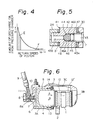
- Fig. 6 shows a typical prior art floating caliper type disc brake, wherein a stationary member 2 is mounted on a non-rotatable part of a vehicle (not shown) at one side (left side in the drawing) of a rotatable disc 1.
- a caliper 3 consisting of an inner leg portion 3A, an outer leg portion 3C and a bridge portion 3B is mounted on the stationary member 2 to slide in the direction parallel to the axis of the disc 1 (transverce direction in the drawing), and a cylinder 4 is formed in the inner leg portion 3A.
- a piston 5 is slidably fitted in the cylinder 4, and a pressure chamber 6 is defined in the cylinder 4 by the piston 5.
- a hydraulic pressure inlet port 7 is formed in the inner leg portion 3A to open in the pressure chamber 6.
- a connecting member 8 is fixedly mounted on the inlet port 7 and is connected to a source of hydraulic pressure such as a master cylinder (no shown) through a piping 9.
- An oil passage 8A is formed in the connecting member 8 with one end communicating to the piping 9 and the other end communicating to the inlet port 7. Shown at 10 and 11 are seal members.
- a pair of friction pads 12 and 12 ⁇ are disposed on opposite sides of the disc 1.
- the piston 5 When liquid under pressure is supplied to the pressure chamber 6, the piston 5 is displaced in arrow A direction in the drawing and presses the friction pad 12 against one side (left side) of the disc 1.
- the reaction force of the piston 5 acts on the bottom of the cylinder 4 to displace the caliper 3 in arrow B direction, whereby the friction pad 12 ⁇ is pressed against the other side (right side) of the disc 1.
- Shown at 13 is a resilient seal ring for preventing the leakage between the cylinder 4 and the piston 5 and for biasing the piston 5 in arrow B direction when the hydraulic pressure in the pressure chamber 6 is released.
- Shwon at 14 is a dust preventing seal.
- the caliper 3 is slidably mounted on the stationary member 2 in arrows A and B directions, thus, there is a shortcoming such that when the vehicle is running on a snowed road a mass of snow may sometimes bump on the caliper 3 to displace shockingly the caliper 3 in arrow A direction, whereby, since the movement of the piston 5 is restricted by the disc 1 through the friction pad 12 the piston 5 may be excessively pushed into the cylinder 4 thereby generating so-called over-return phenomenon of the piston.
- the liquid in the pressure chamber 6 is exhausted to a reservoir through the inlet port 7, the connecting member 8 and the piping 9 by a large amount, which requires a supply of pressurized liquid into the pressure chamber 6 by a large amount in applying brakes thereby preventing normal brake applying operation.
- a disc brake of the type including a stationary member, a caliper slidably mounted on the stationary member and straddling a rotatable disc, a pair of friction pads disposed on opposite sides of the disc, a hydraulic cylinder and piston device incorporated in the caliper for applying one of friction pads against one side of the disc and for applying the other friction pad against the other side of the disc through the caliper, and a liquid passage for connecting the cylinder and piston device with a source of hydraulic pressure, wherein a check valve is provided in the liquid passage for permitting the liquid flow toward the cylinder and piston device and preventing the liquid flow in the opposite direction, and a throttling passage is provided to by-pass the check valve and to permit a restricted liquid flow in both directions.
- the over-return phenomenon of the piston can effectively prevented by a simple construction.
- the disc brake shown in Fig. 1 is generally similar to the disc brake shwon in Fig. 6 and, accordingly, the same reference numerals are applied to corresponding parts and detailed description therefor is omitted.
- a valve casing 21 is screw-threadingly connected to the caliper 3 to substitute the connecting member 8 in the prior art disc brake.
- An axial passage 22 including a large diameter bore 22A and a small diameter bore 22B is formed in the valve casing 21, and a truncated conical valve seat 23 is formed between the large diameter bore 22A and the small diameter bore 22B.
- the valve casing 21 is connected to a piping 24 which is connected to a master cylinder (not shown) acting as a source of hydraulic pressure.
- the passage 22 and the piping 24 constitute a liquid passage connecting the source of hydraulic pressure to the pressure chamber 6.
- a generally cylindrical valve member 25 is slidably fitted in the large diameter bore 22A of the passage 22, and is adapted to engage with the valve seat 23 thereby closing the passage 22.
- a split retaining ring 26 is fitted in an annular groove formed in the large diameter bore 22A, and a coil spring 27 is disposed between the retaining ring 26 and the valve member 25 to bias the valve member 25 against the valve seat 23.
- the valve casing 21, the valve seat 23, the valve member 25 and the spring 27 constitute a check valve according to the invention for permitting liquid flow in the direction toward the pressure chamber 6.
- Shown at 29 in Fig. 1 is a throttling passage axially extending through the central portion of the valve member 25.
- the passage 29 has the effective passage area substantially smaller than that of the small diameter bore 22B and communicates permanently the opposite sides of the valve member 25.
- the throttling passage 29 by-passes the check valve and permits a restricted liquid flow in opposite directions.
- Shown at 30 and 31 in Fig. 1 are seal members.
- the piston 5 displaces in arrow B direction by the resilient force of the resilient seal member 13 at a relatively slow speed.
- the valve member 25 is returned to the valve closing position (Fig. 2), thus, the liquid in the pressure chamber 6 returns to a reservoir through a large diameter bore 22A in the valve casing 21, the throttling passage 29 in the valve member 25, the small diameter bore 22B in the valve casing 21 and the piping 24.
- the friction pads 12 and 12 ⁇ seperate from the disc 1 similarly to prior art disc brakes.
- the liquid discharged from the pressure chamber 6 through the throttling passage 29 receives a resistance force in passing through the throttling passage 29, thus, there is a predetermined relationship, as shown in Fig. 4, between return speed Vp of the piston 5 and the amount of liquid discharged from the pressure chamber 6.
- the return speed Vp of the piston 5 is relatively low corresponding to hatched area portion E in Fig. 4, thus, the liquid flow in the passage 29 is relatively large. Accordingly, the liquid in the chamber 6 is discharged into the master cylinder smoothly and effectively, and the braking force is released smoothly.
Landscapes
- Engineering & Computer Science (AREA)
- General Engineering & Computer Science (AREA)
- Mechanical Engineering (AREA)
- Braking Arrangements (AREA)
Priority Applications (1)
| Application Number | Priority Date | Filing Date | Title |
|---|---|---|---|
| EP86302547A EP0240625A1 (de) | 1986-04-07 | 1986-04-07 | Scheibenbremse |
Applications Claiming Priority (1)
| Application Number | Priority Date | Filing Date | Title |
|---|---|---|---|
| EP86302547A EP0240625A1 (de) | 1986-04-07 | 1986-04-07 | Scheibenbremse |
Publications (1)
| Publication Number | Publication Date |
|---|---|
| EP0240625A1 true EP0240625A1 (de) | 1987-10-14 |
Family
ID=8195955
Family Applications (1)
| Application Number | Title | Priority Date | Filing Date |
|---|---|---|---|
| EP86302547A Withdrawn EP0240625A1 (de) | 1986-04-07 | 1986-04-07 | Scheibenbremse |
Country Status (1)
| Country | Link |
|---|---|
| EP (1) | EP0240625A1 (de) |
Cited By (4)
| Publication number | Priority date | Publication date | Assignee | Title |
|---|---|---|---|---|
| DE4243183A1 (de) * | 1992-12-19 | 1994-06-23 | Teves Gmbh Alfred | Scheibenbremse mit Verdrehsicherung für den Bremsschlauch |
| EP2703683A4 (de) * | 2011-04-21 | 2015-12-09 | Kayaba Industry Co Ltd | Sattelbremsenvorrichtung für ein fahrzeug |
| GB2556072A (en) * | 2016-11-17 | 2018-05-23 | Jaguar Land Rover Ltd | A valve, an internal combustion engine and a vehicle |
| US20230184303A1 (en) * | 2021-12-13 | 2023-06-15 | Jhih-Hua Zeng | Brake fluid pipe detector |
Citations (10)
| Publication number | Priority date | Publication date | Assignee | Title |
|---|---|---|---|---|
| DE726761C (de) * | 1940-07-17 | 1942-10-20 | Teves Kg Alfred | Sicherheitsvorrichtung fuer durch Fluessigkeit angetriebene Bremsen, insbesondere bei Kraftfahrzeugen |
| DE738443C (de) * | 1941-06-09 | 1943-10-18 | Teves Kg Alfred | Vorrichtung zur Schaffung eines UEberdruckes in dem Hauptzylinder einer hydraulischen Bremsvorrichtung, insbesondere fuer Kraftfahrzeuge |
| FR1066263A (fr) * | 1951-08-21 | 1954-06-03 | Girling Ltd | Système de freinage à disque rotatif et tampons de friction avec commande hydraulique pour véhicules routiers ou autres |
| GB819222A (en) * | 1956-05-04 | 1959-09-02 | Goodyear Tire & Rubber | Compound pressure brake with automatic control |
| FR1261246A (fr) * | 1959-09-05 | 1961-05-19 | Fiat Spa | Cylindre hydraulique opérateur et multiplicateur de pression, notamment pour les mécanismes hydrauliques de freinage pour véhicules |
| GB1239040A (de) * | 1967-10-24 | 1971-07-14 | ||
| GB1424100A (en) * | 1972-05-22 | 1976-02-04 | Gen Motors Corp | Wheel brake actuator cylinder assemblies |
| US3993171A (en) * | 1975-05-21 | 1976-11-23 | Tonn Erwin W | Fluid seal piston and cylinder assembly for a disc brake |
| DE2851506A1 (de) * | 1978-11-29 | 1980-06-12 | Magirus Deutz Ag | Bremsvorrichtung fuer fahrzeuge |
| EP0069658A1 (de) * | 1981-07-08 | 1983-01-12 | Societe Anonyme D.B.A. | Druckhalteventil für Resthaltedruck für eine Druckerzeugungseinheit zur Installation von hydraulischen Bremsanlagen |
-
1986
- 1986-04-07 EP EP86302547A patent/EP0240625A1/de not_active Withdrawn
Patent Citations (10)
| Publication number | Priority date | Publication date | Assignee | Title |
|---|---|---|---|---|
| DE726761C (de) * | 1940-07-17 | 1942-10-20 | Teves Kg Alfred | Sicherheitsvorrichtung fuer durch Fluessigkeit angetriebene Bremsen, insbesondere bei Kraftfahrzeugen |
| DE738443C (de) * | 1941-06-09 | 1943-10-18 | Teves Kg Alfred | Vorrichtung zur Schaffung eines UEberdruckes in dem Hauptzylinder einer hydraulischen Bremsvorrichtung, insbesondere fuer Kraftfahrzeuge |
| FR1066263A (fr) * | 1951-08-21 | 1954-06-03 | Girling Ltd | Système de freinage à disque rotatif et tampons de friction avec commande hydraulique pour véhicules routiers ou autres |
| GB819222A (en) * | 1956-05-04 | 1959-09-02 | Goodyear Tire & Rubber | Compound pressure brake with automatic control |
| FR1261246A (fr) * | 1959-09-05 | 1961-05-19 | Fiat Spa | Cylindre hydraulique opérateur et multiplicateur de pression, notamment pour les mécanismes hydrauliques de freinage pour véhicules |
| GB1239040A (de) * | 1967-10-24 | 1971-07-14 | ||
| GB1424100A (en) * | 1972-05-22 | 1976-02-04 | Gen Motors Corp | Wheel brake actuator cylinder assemblies |
| US3993171A (en) * | 1975-05-21 | 1976-11-23 | Tonn Erwin W | Fluid seal piston and cylinder assembly for a disc brake |
| DE2851506A1 (de) * | 1978-11-29 | 1980-06-12 | Magirus Deutz Ag | Bremsvorrichtung fuer fahrzeuge |
| EP0069658A1 (de) * | 1981-07-08 | 1983-01-12 | Societe Anonyme D.B.A. | Druckhalteventil für Resthaltedruck für eine Druckerzeugungseinheit zur Installation von hydraulischen Bremsanlagen |
Non-Patent Citations (1)
| Title |
|---|
| PATENTS ABSTRACTS OF JAPAN, vol. 9, no. 264 (M-423)[1987], 22nd October 1985; & JP-A-60 110 556 (AKEBONO BRAKE KOGYO K.K.) 17-06-1985 * |
Cited By (7)
| Publication number | Priority date | Publication date | Assignee | Title |
|---|---|---|---|---|
| DE4243183A1 (de) * | 1992-12-19 | 1994-06-23 | Teves Gmbh Alfred | Scheibenbremse mit Verdrehsicherung für den Bremsschlauch |
| DE4243183B4 (de) * | 1992-12-19 | 2005-10-20 | Continental Teves Ag & Co Ohg | Scheibenbremse mit Verdrehsicherung für den Bremsschlauch |
| EP2703683A4 (de) * | 2011-04-21 | 2015-12-09 | Kayaba Industry Co Ltd | Sattelbremsenvorrichtung für ein fahrzeug |
| GB2556072A (en) * | 2016-11-17 | 2018-05-23 | Jaguar Land Rover Ltd | A valve, an internal combustion engine and a vehicle |
| GB2556072B (en) * | 2016-11-17 | 2020-09-16 | Jaguar Land Rover Ltd | A valve for restricting the flow of fluid |
| US20230184303A1 (en) * | 2021-12-13 | 2023-06-15 | Jhih-Hua Zeng | Brake fluid pipe detector |
| US12253128B2 (en) * | 2021-12-13 | 2025-03-18 | Jhih-Hua Zeng | Brake fluid pipe detector |
Similar Documents
| Publication | Publication Date | Title |
|---|---|---|
| US4055238A (en) | Anti-squeal device in disc brake | |
| US4488622A (en) | Spot-type floating-caliper disc brake | |
| US4611691A (en) | Hydraulic actuator assemblies for vehicle brakes | |
| GB2129878A (en) | Hydraulic actuating unit | |
| US3476220A (en) | Hydraulic disc brake apparatus and multiple operators therefor | |
| US4309934A (en) | Hydraulic brake booster | |
| US3576236A (en) | Tandem hydraulic brake actuator | |
| JPS59117906A (ja) | 油圧作動装置 | |
| US2746575A (en) | Disc brakes for road and other vehicles | |
| US3122222A (en) | Combination automatic adjuster and deflection absorbing mechanism | |
| US3283860A (en) | Servo actuated disc braking system | |
| EP0049969A1 (de) | Hauptzylinderaufbau für ein hydraulisches Fahrzeugbremssystem | |
| JP2714631B2 (ja) | ディスクブレーキ | |
| KR100534847B1 (ko) | 브레이크 캘리퍼 | |
| US4371059A (en) | Automatic adjusting device in a disc brake | |
| KR100254415B1 (ko) | 차량용 제동장치 | |
| JPS5813765B2 (ja) | ブレ−キシリンダソウチ | |
| US3477232A (en) | Brake arrester | |
| JPH051704Y2 (de) | ||
| JPH0722503Y2 (ja) | ディスクブレーキ用キャリパ | |
| EP0203729A1 (de) | Scheibenbremsen mit Selbstverstärkung | |
| KR200152252Y1 (ko) | 차량용 브레이크캘리퍼의 복원력 보강구조 | |
| KR100466131B1 (ko) | 디스크브레이크의 저더 저감장치 | |
| KR0140284Y1 (ko) | 슬라이딩 캘리퍼의 에어블리딩 스위치 | |
| JPS61215818A (ja) | デイスクブレ−キ |
Legal Events
| Date | Code | Title | Description |
|---|---|---|---|
| PUAI | Public reference made under article 153(3) epc to a published international application that has entered the european phase |
Free format text: ORIGINAL CODE: 0009012 |
|
| 17P | Request for examination filed |
Effective date: 19860421 |
|
| AK | Designated contracting states |
Kind code of ref document: A1 Designated state(s): DE FR GB IT |
|
| 17Q | First examination report despatched |
Effective date: 19880428 |
|
| STAA | Information on the status of an ep patent application or granted ep patent |
Free format text: STATUS: THE APPLICATION IS DEEMED TO BE WITHDRAWN |
|
| 18D | Application deemed to be withdrawn |
Effective date: 19880912 |
|
| RIN1 | Information on inventor provided before grant (corrected) |
Inventor name: NAKAYAMA, SHINICHI Inventor name: KOBAYASHI, KINZO |