EP0240730A1 - Direkt beheizte Walze zur Wärmefixierung von Tonerbildern - Google Patents
Direkt beheizte Walze zur Wärmefixierung von Tonerbildern Download PDFInfo
- Publication number
- EP0240730A1 EP0240730A1 EP87103145A EP87103145A EP0240730A1 EP 0240730 A1 EP0240730 A1 EP 0240730A1 EP 87103145 A EP87103145 A EP 87103145A EP 87103145 A EP87103145 A EP 87103145A EP 0240730 A1 EP0240730 A1 EP 0240730A1
- Authority
- EP
- European Patent Office
- Prior art keywords
- layer
- roller
- alloy
- insulating layer
- heat generating
- Prior art date
- Legal status (The legal status is an assumption and is not a legal conclusion. Google has not performed a legal analysis and makes no representation as to the accuracy of the status listed.)
- Granted
Links
- 239000010410 layer Substances 0.000 claims abstract description 136
- 239000000919 ceramic Substances 0.000 claims abstract description 18
- 239000011159 matrix material Substances 0.000 claims abstract description 14
- 239000011241 protective layer Substances 0.000 claims abstract description 9
- 230000002093 peripheral effect Effects 0.000 claims abstract description 6
- 229910052751 metal Inorganic materials 0.000 claims abstract description 5
- 239000002184 metal Substances 0.000 claims abstract description 5
- 238000010438 heat treatment Methods 0.000 claims description 39
- 229910045601 alloy Inorganic materials 0.000 claims description 34
- 239000000956 alloy Substances 0.000 claims description 34
- 229910018487 Ni—Cr Inorganic materials 0.000 claims description 27
- XEEYBQQBJWHFJM-UHFFFAOYSA-N Iron Chemical compound [Fe] XEEYBQQBJWHFJM-UHFFFAOYSA-N 0.000 claims description 18
- 239000000463 material Substances 0.000 claims description 15
- PNEYBMLMFCGWSK-UHFFFAOYSA-N aluminium oxide Inorganic materials [O-2].[O-2].[O-2].[Al+3].[Al+3] PNEYBMLMFCGWSK-UHFFFAOYSA-N 0.000 claims description 10
- 229910052593 corundum Inorganic materials 0.000 claims description 10
- 229910001845 yogo sapphire Inorganic materials 0.000 claims description 10
- 229910052742 iron Inorganic materials 0.000 claims description 9
- 229910001182 Mo alloy Inorganic materials 0.000 claims description 6
- MCMNRKCIXSYSNV-UHFFFAOYSA-N Zirconium dioxide Chemical compound O=[Zr]=O MCMNRKCIXSYSNV-UHFFFAOYSA-N 0.000 claims description 6
- 229910052596 spinel Inorganic materials 0.000 claims description 6
- 229910026161 MgAl2O4 Inorganic materials 0.000 claims description 4
- 229910003310 Ni-Al Inorganic materials 0.000 claims description 4
- 229910000640 Fe alloy Inorganic materials 0.000 claims description 2
- CPLXHLVBOLITMK-UHFFFAOYSA-N magnesium oxide Inorganic materials [Mg]=O CPLXHLVBOLITMK-UHFFFAOYSA-N 0.000 claims description 2
- VYPSYNLAJGMNEJ-UHFFFAOYSA-N Silicium dioxide Chemical compound O=[Si]=O VYPSYNLAJGMNEJ-UHFFFAOYSA-N 0.000 claims 2
- 229910000599 Cr alloy Inorganic materials 0.000 claims 1
- 229910052681 coesite Inorganic materials 0.000 claims 1
- 229910052906 cristobalite Inorganic materials 0.000 claims 1
- 239000000377 silicon dioxide Substances 0.000 claims 1
- 235000012239 silicon dioxide Nutrition 0.000 claims 1
- 229910052682 stishovite Inorganic materials 0.000 claims 1
- 229910052905 tridymite Inorganic materials 0.000 claims 1
- 238000002474 experimental method Methods 0.000 description 9
- 238000009826 distribution Methods 0.000 description 7
- 238000000034 method Methods 0.000 description 7
- XKRFYHLGVUSROY-UHFFFAOYSA-N Argon Chemical compound [Ar] XKRFYHLGVUSROY-UHFFFAOYSA-N 0.000 description 6
- 230000035939 shock Effects 0.000 description 6
- 229910052782 aluminium Inorganic materials 0.000 description 5
- 238000007750 plasma spraying Methods 0.000 description 5
- 238000012360 testing method Methods 0.000 description 5
- XAGFODPZIPBFFR-UHFFFAOYSA-N aluminium Chemical compound [Al] XAGFODPZIPBFFR-UHFFFAOYSA-N 0.000 description 4
- 229910010293 ceramic material Inorganic materials 0.000 description 4
- 238000009413 insulation Methods 0.000 description 4
- 239000000203 mixture Substances 0.000 description 4
- 238000005507 spraying Methods 0.000 description 4
- 229910052786 argon Inorganic materials 0.000 description 3
- 229910052736 halogen Inorganic materials 0.000 description 3
- 238000001000 micrograph Methods 0.000 description 3
- 239000000843 powder Substances 0.000 description 3
- 229910000838 Al alloy Inorganic materials 0.000 description 2
- RTZKZFJDLAIYFH-UHFFFAOYSA-N Diethyl ether Chemical compound CCOCC RTZKZFJDLAIYFH-UHFFFAOYSA-N 0.000 description 2
- 229910000831 Steel Inorganic materials 0.000 description 2
- 238000005452 bending Methods 0.000 description 2
- 230000015556 catabolic process Effects 0.000 description 2
- 230000006866 deterioration Effects 0.000 description 2
- 239000007789 gas Substances 0.000 description 2
- 150000002367 halogens Chemical class 0.000 description 2
- 230000020169 heat generation Effects 0.000 description 2
- 239000002245 particle Substances 0.000 description 2
- 230000005855 radiation Effects 0.000 description 2
- 229920005989 resin Polymers 0.000 description 2
- 239000011347 resin Substances 0.000 description 2
- 238000004904 shortening Methods 0.000 description 2
- 239000011029 spinel Substances 0.000 description 2
- 239000010959 steel Substances 0.000 description 2
- -1 tungsten halogen Chemical class 0.000 description 2
- 229910000990 Ni alloy Inorganic materials 0.000 description 1
- 239000000654 additive Substances 0.000 description 1
- 229910052804 chromium Inorganic materials 0.000 description 1
- 229920006026 co-polymeric resin Polymers 0.000 description 1
- 238000010276 construction Methods 0.000 description 1
- 230000002844 continuous effect Effects 0.000 description 1
- 230000007423 decrease Effects 0.000 description 1
- 230000000694 effects Effects 0.000 description 1
- 230000005611 electricity Effects 0.000 description 1
- 239000011810 insulating material Substances 0.000 description 1
- 238000005259 measurement Methods 0.000 description 1
- 150000002739 metals Chemical class 0.000 description 1
- 229910052750 molybdenum Inorganic materials 0.000 description 1
- 238000013021 overheating Methods 0.000 description 1
- 238000004321 preservation Methods 0.000 description 1
- 230000000630 rising effect Effects 0.000 description 1
- 239000007921 spray Substances 0.000 description 1
- 238000012546 transfer Methods 0.000 description 1
- 229910052721 tungsten Inorganic materials 0.000 description 1
- 239000010937 tungsten Substances 0.000 description 1
- 230000000007 visual effect Effects 0.000 description 1
Images


Classifications
-
- G—PHYSICS
- G03—PHOTOGRAPHY; CINEMATOGRAPHY; ANALOGOUS TECHNIQUES USING WAVES OTHER THAN OPTICAL WAVES; ELECTROGRAPHY; HOLOGRAPHY
- G03G—ELECTROGRAPHY; ELECTROPHOTOGRAPHY; MAGNETOGRAPHY
- G03G15/00—Apparatus for electrographic processes using a charge pattern
- G03G15/20—Apparatus for electrographic processes using a charge pattern for fixing, e.g. by using heat
-
- H—ELECTRICITY
- H05—ELECTRIC TECHNIQUES NOT OTHERWISE PROVIDED FOR
- H05B—ELECTRIC HEATING; ELECTRIC LIGHT SOURCES NOT OTHERWISE PROVIDED FOR; CIRCUIT ARRANGEMENTS FOR ELECTRIC LIGHT SOURCES, IN GENERAL
- H05B3/00—Ohmic-resistance heating
- H05B3/0095—Heating devices in the form of rollers
-
- G—PHYSICS
- G03—PHOTOGRAPHY; CINEMATOGRAPHY; ANALOGOUS TECHNIQUES USING WAVES OTHER THAN OPTICAL WAVES; ELECTROGRAPHY; HOLOGRAPHY
- G03G—ELECTROGRAPHY; ELECTROPHOTOGRAPHY; MAGNETOGRAPHY
- G03G15/00—Apparatus for electrographic processes using a charge pattern
- G03G15/20—Apparatus for electrographic processes using a charge pattern for fixing, e.g. by using heat
- G03G15/2003—Apparatus for electrographic processes using a charge pattern for fixing, e.g. by using heat using heat
- G03G15/2014—Apparatus for electrographic processes using a charge pattern for fixing, e.g. by using heat using heat using contact heat
- G03G15/2053—Structural details of heat elements, e.g. structure of roller or belt, eddy current, induction heating
- G03G15/2057—Structural details of heat elements, e.g. structure of roller or belt, eddy current, induction heating relating to the chemical composition of the heat element and layers thereof
Definitions
- This invention relates to fixing device for fixing toner images to paper or sheet in electrophotographic copiers and printers, particularly to improvement of heat fuse fixing roller (hereinafter referred to as heating roller).
- Electrophotographic copiers and printers make use of toners for developing electrostatic latent images.
- the developed images are fixed on sheets or the like members to form permanent visual images.
- a method for fixing the developed images namely, a method called “heat fuse-fixing” in which resin particles in the toner are heated and fused on the sheet, and a method called “pressure fuse-fixing” in which resin particles are fused by application of pressure.
- heat roller fixing device a device which is referred to as "heat roller fixing device” has been broadly used because of its superior characteristics, namely, stable fixing performance over wide speed range of developing machine, high thermal efficiency and safety.
- This device has a heat roller which is heated by a tungsten halogen lamp provided inside the roller.
- This constitution undesirably requires a large electric power consumption and long warming-up time.
- the roller temperature is lowered when many sheets are treated successively, because the heating output cannot well compensate for the temperature drop of the roller.
- the warm-up time is preferably 30 seconds, more preferably 20 seconds or shorter, while the electric power consumption is preferably less than l KW, more preferably about 700 W or smaller. It is also preferred that the roller temperature is stably maintained around 200°C.
- the roller exhibits a uniform temperature distribution over its entire surface.
- the heat roller tends to exhibit higher temperature at its mid portion than at its both axial ends. This tendency is increased particularly when the resistance film has a positive temperature coefficient, i.e., such a characteristic that the electric resistance is increased in accordance with a temperature rise.
- the portion of the resistance film on the mid portion of the roller exhibits a greater resistance than the film portions on both axial ends of the roller, so that the electric current which flows from one to the other axial ends encounters a greater resistance at the mid portion of the roller, so that greater heat is generated at this portion of the roller thereby causing a further temperature at the mid portion of the roller.
- the resistance film does not have large positive temperature coefficient.
- the resistance film could have a negative temperature coefficient, that is, such a characteristic that electric resistance decreases as temperature rises.
- the heat generation is smaller at the mid portion of the roller than at both axial end portions of the same, contributing to the uniform temperature distribution along the axis of the roller.
- the resistance film exhibits a very large electric resistance such as to restrict the flow of the electric current, so that an impractically long time is required for heating up the roller.
- the use of a resistance film having a negative temperature coefficient does not meet the demand for shortening of the warm-up time.
- the control of the temperature of the resistance film is conducted by a control circuit which judges the film temperature by sensing the electric current, and varying the electric current in accordance with the measured temperature so as to maintain a constant film temperature.
- the resistance film having a negative temperature coefficient reduces its resistance when the temperature becomes high. If the electric resistance of a circuit for supplying the electric power is increased due to an unexpected reason such as an insufficient contact of terminals or contacts in the circuit, the temperature control circuit erroneously judges that the resistance film temperature has come down and operates to supply greater electric current to the resistance film. From the view point of stability of the temperature control, therefore, it is preferred that the resistance film has a positive temperature coefficient. And when the temperature increases unnormally by an accident of relay short, the resistance film of negative temperature coefficient is rapidly heated since electric power increases on over-heating.
- resistance value of the resistance film is as constant as possible.
- an object of the invention is to provide a directly-heating roller for fuse-fixing toner images, which has na extremely short warm-up time and high durability against repeated thermal shock, over conventional directly-heating fuse-fixing rollers.
- Another object of the invention is to provide a directly-heating roller provided with a resistance film which has a slight positive temperature coefficient.
- a directly-heating roller for fuse-fixing toner images comprising: (a) a roller body having a small heat capacity; (b) a bonding formed substantially uniformly on the outer peripheral surface of the roller body; (c) a lower insulating layer provided on the bonding layer; (d) a heat generating layer provided on the lower insulating layer and having a ceramic matrix and a metallic resistance layer constituted by a metal dispersed in the ceramic matrix, the metallic resistance layer extending substantially electrically continuously at least in the lengthwise direction of the roller, the heat generating layer having a thermal expansion coefficient substantially the same as that of the lower insulating layer; (e) an upper insulating layer provided on the heat generating layer; (f) a protective layer formed on the upper insulating layer so as to prevent offset of the toner images; and (g) an electrode layer formed on each end of the roller and adapted to connect the heat generating layer to an external power source.
- the heat generating layer has a ceramic matrix and a metallic resistor embedded in the matrix, the metallic resistor extending continuously at least in the longitudinal direction.
- This heat generating layer has a thermal expansion coefficient which is substantially the same as the insulating material.
- the heat generating layer has an adequate resistivity, and the directly-heating roller can withstand the repeated thermal shocks.
- a bonding layer 2 is deposited substantially uniformly onto the outer peripheral surface of the roller portion of a cylindrical roller body l.
- a lower insulating layer 3 is deposited on the bonding layer 2, and a heat generating layer 4 is formed on the lower insulating layer 3.
- An upper insulating layer 5 is formed on the heat generating resistance layer 4.
- a protective layer 6 is provided on the upper insulating layer 5.
- An electrode layer 7 is formed on the portion of the heat generating resistance layer 4 on each end portion of the roller l.
- the directly-heating roller having the described construction when incorporated in a copier or a similar machine, is journaled at its both ends by bearings for rotation.
- the directly-heating roller is arranged to oppose a rubber roller such as to form therebetween a nip through which a sheet carrying a toner image is passed so that the toner images are fixed.
- the heat generating resistance layer 4 is formed from a material having a composition containing l0 to 35 wt% of an Ni-Cr alloy and the balance substantially a ceramic material.
- the heat generating resistance layer 4 is produced from the above-mentioned material by arc-plasma spraying, such that the Cr-Ni alloy is dispersed so as to form a lengthwise continuous layer in the ceramic material.
- the Ni-Cr alloy content is below l0 wt%, the alloy is dispersed discontinuously, so that the continuous lengthwise layer cannot be formed, with a result that the heat generating resistance layer exhibits a very large resistance.
- Ni-Cr alloy ordinarily used as a heat-generating conductive means can be used as the Ni-Cr alloy in the heat generating resistance layer 4.
- the Ni-Cr alloy contains 5 to 20 wt% of Cr and the balance substan tially Ni, although some other additives in heat generating resistance layer and incidental elements are not excluded.
- the ceramic matrix of the heat generating resistance layer is preferably formed from Al2O3. It has been confirmed that when Al2O3 is used as the ceramic matrix, the Ni-Cr alloy can be well dispersed in the matrix in such a manner as to form a continuous lengthwise layer.
- Figs. 3 and 4 show, respectively, the microphotos of structures of the layers having Ni-Cr alloy content of 20 wt% and 8 wt%, respectively.
- Fig. 3(a) and (b) are microphotographs of the structure of a heat generating resistance film (X-X section and Y-Y section of Fig. l, respectively). From Fig.
- Ni-Cr alloy content of 8 wt% cannot have con tinuous Ni-Cr alloy layer, resulting in a large electric resistance and reduced durability against repeated thermal shocks.
- the heating material comprising 8 wt% Ni-Cr alloy is described in Yasuo Tsukuda et al S.N. 686,850 in the U.S. and EPC patent application 84308907.9 ssigned to the same assignee.
- this heat generating resistance layer has a thermal expansion coefficient ⁇ of 6 ⁇ l0 ⁇ 6 to l0 ⁇ l0 ⁇ 6/deg.
- the insulating layers sandwiching this heat generating resistance layse have a thermal expansion coefficient of not smaller than 6 ⁇ l0 ⁇ 6/deg.
- Materials of insulating layer practically usable are: Al2O3, MgO, ZrO2, MgAl2O4 (spinel), ZrO2SiO2, MnO.NiO, etc.
- the spinel MgAl2O4 is preferred because of high temperature preservation effect which in turn contributes to the shortening of the warm-up time of the roller.
- the lower insulating layer electrically insulates the heat generating layer from the roller body and prevents transfer of heat from the resistance layer to the roller body.
- a too large thickness of the lower insulating layer will result in a long warm-up time of the heating roller because of long time required for heating the lower insulating layer, while a too small thickness cannot provide sufficient electric insulation.
- the thickness of the lower insulating layer preferably ranges between 200 and 500 ⁇ m, and most preferably about 300 ⁇ m.
- the upper insulating layer serves to uniformize the temperature distribution which otherwise does not become uniform due to the uniformity of heat generation caused by the partial ununiformity of heat generating resistor, and serves also to ensure sufficient electric insulation of the roller surface.
- the layer may protect the resistance layer when other material comes in the nip of the fixing device.
- the upper insulating layer also prolongs the warm-up time when its thickness is too large, while impairs the electric insulation when its thickness is too small.
- the preferred range of thickness of the upper insulating layer is 30 to 200 ⁇ m, more preferably about l00 ⁇ m.
- the roller body was usually made of a high-strength aluminum alloy (5056), in order to meet a demand for high formability, as well as uniform and quick heating characteristics.
- the directly-heating roller of the invention has a body which has a small heat capacity.
- the material of the roller body has a thermal expansion coefficient which approximates that of the ceramic.
- the roller body of the roller in accordance with the invention is made of iron or an iron alloy.
- soft iron exhibits a thermal expansion coefficient value of l0 ⁇ l0 ⁇ 6/deg. which is the smallest among those of metals.
- it is difficult to reduce the thickness of the aluminum pipe because it cannot stand bending stress caused fixing pressure because bending strength of aluminum pipe(5056) is less than l/2 of soft iron at 200°C.
- Hc is needed for calculating necessary heat value heating a heating roller to 200°C.
- Hc can be separated to heat capacity of metal portions (roller body and bonding film) and heat capacity of ceramic portions including heat generating layer. These are referred to as Hcm and Hcc, respectively.
- Delta-Hs includes heat-leakage from surface by convention and radiation. Since these changes according to temperature, average value is used as delta-Hs. Similarly, delta-Hcon is average value. Delta-Hcon means leakage to other machine parts through journals.
- the reduction of heat capacity can be accomplished by thinning each layer and thickness of roller body or by changing materials. Materials change has some difficulty but thinning the thickness is easier.
- roller body with low thermal conductity may reduce the leakage.
- steel or soft iron is preferable to aluminum alloy as roller body, since steel or soft iron has lower conductivity and is workable to thin thickness. It is also possible to form the roller body in a cylindrical form which has a small thickness of 2 mm or less, preferably l mm or less, so as to reduce the heat capacity.
- the bonding film bonds the lower insulating layer to the surface of the roller body.
- Ni-Cr-Mo alloy, Ni-Al alloy, Ni-Cr alloy or the like is suitably used as the material of the bonding surface.
- powdered Ni coated on the surface thereof with Al and Mo is used most preferably.
- the protective layer coats the surface of the upper insulating layer, in order to imrove the anti-offset characteristics of the toner images and also for the purpose of insulating the surface of the roller.
- the protective layer is formed from a PEA (tetrafluoroethyleneperfluoroalkylvinyl ether copolymer resin) at a thickness of 30 ⁇ m.
- a plasma spray apparatus used in this experiment comprised a gun body having a central path for flowing an operation gas, argon. A part of the path was enclosed by an anode, and a rod-type cathode was mounted in the path. A path for supplying powder mixtures to be sprayed was open to the central path near a nozzle opening.
- Powders to be sprayed were supplied through the side path into the plasma formed in the central path.
- the roller was rotating to form uniform deposited layer on it while the roller was placed at the distance of l0 cm from the plasma jet.
- the warm-up time was 40 seconds in the roller having roller body thickness of l.5 mm, and 30 seconds and 22 seconds, respectively, when the roller body thickness was l.0 mm and 0.6 mm. It will be seen that the directly heating roller of the invention has a very short warm-up time.
- roller body thickness of less than 2mm results of shorter warm-up time. Thickness of less than lmm drastically shortens the warm-up time. But, thickness of less than 0.4mm cannot stand fixing pressure and is difficult to produce.
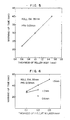
- Directly-heating rollers were prepared in the same way as Experiment l, with the thickness of the lower insulating layer varied as l00 ⁇ m, 300 ⁇ m and 500 ⁇ m. Electric current was supplied to the rollers such that it produces power of 900 Watts and the period of time required for heating the roller surfaces up to 200°C was measured as the warm-up time. As will be seen from Fig. 6 which shows the result of the measurement, the warm-up time is shortened as the roller body thickness is reduced and as the insulating layer thickness is reduced. But, l00 ⁇ m shows poor electric insulating and more than 500 ⁇ m causes long warm-up time.
- the directly-heating roller having the roller body thickness of 0.6 mm employed in Experiment l was subjected to a repetitional heat cycle test.
- the heating roller was held in contact with a rubber roller of a diameter substantially the same as that of the heating roller, while being rotated at a peripheral speed of 200 mm/sec.
- the heat cycle test was conducted by apply ing the roller to repetitional heat cycles as shown in Fig. 7.
- the heat roller in accordance with the invention showed no breakdown of the resistance layer and no deterioration in the electric characteristics, even after continuous 2600 heat cycles.
- a continuous heat-rotation test was carried out by using a fixing unit of the same type as that used in Experiment 3. Neither breakdown of the resistance layer nor deterioration in the electric characteristics were observed after 650-hour operation at the maximum temperature of 220°C, thus proving the superiority of the heating roller of the invention.
- a copier which fixes images on l2 sheets of A-4 size paper per minute, it takes about 200 hours for fixing images on l50,000 aheets which is the number guaranteed. It will be seen that the heating roller of the invention can withstand the use for a long period of time which is about 3 times as long as the guaranteed period.
- cylindrical roller bodies made of soft iron and having a length of 240 mm, an outer diameter of 35 mm, and a thickness of 0.6 mm.
- a bonding film of Ni-Al-Mo alloy having a thickness of 25 ⁇ m, a lower insulating layer of MgAl2O3 having a thickness of 300 ⁇ m, and an exothermic resistance film of about 70 ⁇ m in thickness including Ni-Al alloy of 20% and the balance Al2O3, in turn.
- the resistance film is made to have a thickness of 65-70 ⁇ m which film is made to have a substantially uniform thickness in the range from the end of the roller to the center thereof, while in a roller B the resistance film is made to have a thickness of 55 ⁇ m at both ends thereof and another thickness of 70 ⁇ m at the center thereof.
- Onto each of these resistance films were plasma-sprayed an upper insulating layer having a thickness of l00 ⁇ m and a protective layer of PFA in turn, whereby a directly-heating rollers were produced.
Landscapes
- Physics & Mathematics (AREA)
- General Physics & Mathematics (AREA)
- Fixing For Electrophotography (AREA)
- Control Of Resistance Heating (AREA)
- Resistance Heating (AREA)
Applications Claiming Priority (2)
| Application Number | Priority Date | Filing Date | Title |
|---|---|---|---|
| US06/837,178 US4724305A (en) | 1986-03-07 | 1986-03-07 | Directly-heating roller for fuse-fixing toner images |
| US837178 | 1986-03-07 |
Publications (2)
| Publication Number | Publication Date |
|---|---|
| EP0240730A1 true EP0240730A1 (de) | 1987-10-14 |
| EP0240730B1 EP0240730B1 (de) | 1991-04-24 |
Family
ID=25273740
Family Applications (1)
| Application Number | Title | Priority Date | Filing Date |
|---|---|---|---|
| EP87103145A Expired - Lifetime EP0240730B1 (de) | 1986-03-07 | 1987-03-05 | Direkt beheizte Walze zur Wärmefixierung von Tonerbildern |
Country Status (5)
| Country | Link |
|---|---|
| US (1) | US4724305A (de) |
| EP (1) | EP0240730B1 (de) |
| JP (1) | JPS62247386A (de) |
| KR (1) | KR940001086B1 (de) |
| DE (1) | DE3769503D1 (de) |
Cited By (9)
| Publication number | Priority date | Publication date | Assignee | Title |
|---|---|---|---|---|
| US4810858A (en) * | 1987-11-02 | 1989-03-07 | Eastman Kodak Company | Fusing roller |
| US4820904A (en) * | 1987-11-02 | 1989-04-11 | Eastman Kodak Company | Electrical contacting device for fusing roller |
| EP0262833A3 (en) * | 1986-09-22 | 1989-04-19 | Onoda Cement Company, Ltd. | Thermal fixing roller for use in a copying machine and method for manufacturing the same |
| EP0336028A1 (de) * | 1986-10-23 | 1989-10-11 | Hitachi Metals, Ltd. | Beheizbare Rolle für die Elektrofotografie |
| EP0241714B1 (de) * | 1986-03-12 | 1991-03-06 | Hitachi Metals, Ltd. | Direkt beheizte Walze zur Fixierung von Tonerbildern |
| EP0827044A1 (de) * | 1996-08-30 | 1998-03-04 | Xerox Corporation | Schnellaufheizende Schmelzfixiersystemteile |
| WO1999051064A1 (en) * | 1998-03-30 | 1999-10-07 | American Roller Company | Ceramic heater roller with ground shield and fault detection |
| EP1418473A1 (de) * | 2002-11-11 | 2004-05-12 | Samsung Electronics Co., Ltd. | Heizfixierrollervorrichtung für ein elektrophotographisches Bilderzeugungsgerät |
| EP1510883A4 (de) * | 2002-06-03 | 2009-03-25 | Fuji Xerox Co Ltd | Heizwalze |
Families Citing this family (32)
| Publication number | Priority date | Publication date | Assignee | Title |
|---|---|---|---|---|
| US4813372A (en) * | 1986-05-08 | 1989-03-21 | Kabushiki Kaisha Toshiba | Toner image fixing apparatus |
| JPS63307489A (ja) * | 1987-06-09 | 1988-12-15 | Hitachi Metals Ltd | トナ−定着用ヒ−トロ−ル |
| US4976877A (en) * | 1989-09-15 | 1990-12-11 | Eastman Kodak Company | Ceramic cupric oxide coated pressure roll for image fixing |
| DE69024456T2 (de) * | 1989-10-16 | 1996-05-23 | Canon Kk | Adhäsionsfreie elastische Walze |
| JP2745438B2 (ja) * | 1990-07-13 | 1998-04-28 | 株式会社荏原製作所 | 加熱用伝熱材料及び発熱体とそれを用いた加熱装置 |
| US5155800A (en) * | 1991-02-27 | 1992-10-13 | Process Technology Inc. | Panel heater assembly for use in a corrosive environment and method of manufacturing the heater |
| US5286950A (en) * | 1991-03-26 | 1994-02-15 | Kanegafuchi Kagaku Kogyo Kabushiki Kaisha | Fixing device and heat roller therefor |
| KR960008921B1 (en) * | 1991-08-08 | 1996-07-09 | Tech K K | Fixing apparatus |
| US5173736A (en) * | 1991-09-06 | 1992-12-22 | Xerox Corporation | Apparatus and method for fusing marking particles onto a support member |
| US5245392A (en) * | 1992-10-02 | 1993-09-14 | Xerox Corporation | Donor roll for scavengeless development in a xerographic apparatus |
| JPH06186877A (ja) * | 1992-10-21 | 1994-07-08 | Ricoh Co Ltd | 定着装置 |
| US5408070A (en) * | 1992-11-09 | 1995-04-18 | American Roller Company | Ceramic heater roller with thermal regulating layer |
| US5616263A (en) * | 1992-11-09 | 1997-04-01 | American Roller Company | Ceramic heater roller |
| US5722025A (en) * | 1995-10-24 | 1998-02-24 | Minolta Co., Ltd. | Fixing device |
| JPH09120230A (ja) * | 1995-10-25 | 1997-05-06 | Minolta Co Ltd | 定着装置 |
| WO1998051127A1 (en) | 1997-05-06 | 1998-11-12 | Thermoceramix, L.L.C. | Deposited resistive coatings |
| US5978641A (en) * | 1998-10-16 | 1999-11-02 | Xerox Corporation | Coaxial integral heating fusing belt |
| US6222166B1 (en) | 1999-08-09 | 2001-04-24 | Watlow Electric Manufacturing Co. | Aluminum substrate thick film heater |
| KR100365692B1 (ko) | 2000-02-24 | 2002-12-26 | 삼성전자 주식회사 | 토너 화상 정착을 위한 직접 가열 롤러 및 그 제조 방법 |
| JP2004528677A (ja) * | 2000-11-29 | 2004-09-16 | サーモセラミックス インコーポレイテッド | 抵抗加熱器及びその使用法 |
| US6815642B2 (en) * | 2001-12-19 | 2004-11-09 | Delphi Technologies, Inc. | Apparatus and method for heating a steering wheel |
| MXPA04008898A (es) * | 2002-03-13 | 2005-06-20 | Watlow Electric Mfg | Dispositivo calentador de canal caliente y su metodo de fabricacion. |
| JP2004046081A (ja) * | 2002-05-17 | 2004-02-12 | Ricoh Co Ltd | 定着装置、および画像形成装置 |
| US6991003B2 (en) * | 2003-07-28 | 2006-01-31 | M.Braun, Inc. | System and method for automatically purifying solvents |
| DE602004011386T2 (de) * | 2003-11-20 | 2009-01-08 | Koninklijke Philips Electronics N.V. | Dünnschichtheizelement |
| JP2005242321A (ja) * | 2004-01-30 | 2005-09-08 | Canon Inc | 多孔質セラミックスの断熱層を有するローラを用いた像加熱装置 |
| KR100694131B1 (ko) * | 2005-06-25 | 2007-03-12 | 삼성전자주식회사 | 정착롤러 및 상기 정착롤러를 적용한 정착장치 |
| US8154376B2 (en) * | 2007-09-17 | 2012-04-10 | Littelfuse, Inc. | Fuses with slotted fuse bodies |
| EP2290469A1 (de) * | 2009-08-20 | 2011-03-02 | Samsung Electronics Co., Ltd. | Sicherungsvorrichtung mit Widerstandsheizschicht und Bilderzeugungsvorrichtung mit der Sicherungsvorrichtung |
| US8815167B2 (en) * | 2011-09-14 | 2014-08-26 | Toyota Jidosha Kabushiki Kaisha | Electrode, electrically heating type catalyst device using same, and manufacturing method of electrically heating type catalyst device |
| CN112067990B (zh) * | 2020-09-17 | 2023-02-21 | 西安高压电器研究院股份有限公司 | 一种喷射熔断器容量试验布置装置 |
| DE102023118705A1 (de) * | 2023-07-14 | 2025-01-16 | Ams-Osram International Gmbh | Druckvorrichtung, druckverfahren und verfahren zum herstellen einer druckvorrichtung |
Citations (1)
| Publication number | Priority date | Publication date | Assignee | Title |
|---|---|---|---|---|
| EP0147170A2 (de) * | 1983-12-28 | 1985-07-03 | Hitachi Metals, Ltd. | Heizwiderstandsschicht |
Family Cites Families (18)
| Publication number | Priority date | Publication date | Assignee | Title |
|---|---|---|---|---|
| FR992103A (fr) * | 1944-05-10 | 1951-10-15 | élément de chauffage électrique par résistance et son procédé de fabrication | |
| FR1377471A (fr) * | 1963-09-23 | 1964-11-06 | Plaque chauffante à résistance électrique, et procédé pour la fabriques | |
| GB1057982A (en) * | 1964-01-22 | 1967-02-08 | Owens Illinois Inc | Electric resistance heater |
| DE1496665A1 (de) * | 1964-11-18 | 1969-09-11 | Siemens Ag | Verwendung eines glaskeramischen Koerpers als Werkstoff fuer elektrische Widerstandskoerper |
| US3425864A (en) * | 1965-07-21 | 1969-02-04 | Templeton Coal Co | Method for making electric resistance heaters |
| FR1574025A (de) * | 1968-04-03 | 1969-07-11 | ||
| DE1903986A1 (de) * | 1969-01-28 | 1970-08-20 | Tuerk & Hillinger Kg | Verfahren zum Herstellen von elektrischen Heizelementen |
| JPS4832694B1 (de) * | 1969-08-11 | 1973-10-08 | ||
| US3679473A (en) * | 1970-12-23 | 1972-07-25 | Whirlpool Co | Method of making a heating element |
| US3794518A (en) * | 1972-05-01 | 1974-02-26 | Trw Inc | Electrical resistance material and method of making the same |
| FR2262895B1 (de) * | 1974-02-28 | 1978-06-16 | Rhone Poulenc Textile | |
| US4060663A (en) * | 1974-07-24 | 1977-11-29 | Trw Inc. | Electrical resistor glaze composition and resistor |
| GB1501946A (en) * | 1975-11-11 | 1978-02-22 | Ngk Insulators Ltd | Electrical insulators |
| JPS531029A (en) * | 1976-06-25 | 1978-01-07 | Oki Electric Ind Co Ltd | High speed printer |
| US4299887A (en) * | 1979-05-07 | 1981-11-10 | Trw, Inc. | Temperature sensitive electrical element, and method and material for making the same |
| US4395109A (en) * | 1979-06-11 | 1983-07-26 | Tokyo Shibaura Denki Kabushiki Kaisha | Fixing device for electronic duplicator machine |
| JPS57184296A (en) * | 1981-05-09 | 1982-11-12 | Hitachi Ltd | Ceramic circuit board |
| JPS5983181A (ja) * | 1982-11-04 | 1984-05-14 | Minolta Camera Co Ltd | 熱ロ−ラ定着装置 |
-
1986
- 1986-03-07 US US06/837,178 patent/US4724305A/en not_active Expired - Fee Related
-
1987
- 1987-03-05 EP EP87103145A patent/EP0240730B1/de not_active Expired - Lifetime
- 1987-03-05 DE DE8787103145T patent/DE3769503D1/de not_active Expired - Lifetime
- 1987-03-06 JP JP62051778A patent/JPS62247386A/ja active Pending
- 1987-03-07 KR KR1019870002038A patent/KR940001086B1/ko not_active Expired - Fee Related
Patent Citations (1)
| Publication number | Priority date | Publication date | Assignee | Title |
|---|---|---|---|---|
| EP0147170A2 (de) * | 1983-12-28 | 1985-07-03 | Hitachi Metals, Ltd. | Heizwiderstandsschicht |
Non-Patent Citations (5)
| Title |
|---|
| PATENT ABSTRACTS OF JAPAN, vol. 8, no. 171 (P-293)[1608], 8th August 1984; & JP-59 067 567 (HITACHI KINZOKU) 17-04-184 * |
| PATENT ABSTRACTS OF JAPAN, vol. 8, no. 75 (P-266)[1512], 7th April 1984; & JP -A-58 220 165 (RICOH) 21-12-1983 * |
| PATENT ABSTRACTS OF JAPAN, vol. 9, no. 116 (P-357)[1839], 21st May 1985; & JP -A-60 003 683 (HITACHI KINZOKU) 10-01-1985 * |
| PATENT ABSTRACTS OF JAPAN, vol. 9, no. 2 (P-325)[1725], 8th January 1985; & JP-A-59 151 178 (HITACHI KINZOKU) 29-08-1984 * |
| PATENT ABSTRACTS OF JAPAN, vol. 9, no. 6 (P-326)[1729], 11th January 1985; & JP-A-59 154 478 (HITACHI KINZOKU) 03-09-1984 * |
Cited By (14)
| Publication number | Priority date | Publication date | Assignee | Title |
|---|---|---|---|---|
| EP0241714B1 (de) * | 1986-03-12 | 1991-03-06 | Hitachi Metals, Ltd. | Direkt beheizte Walze zur Fixierung von Tonerbildern |
| EP0262833A3 (en) * | 1986-09-22 | 1989-04-19 | Onoda Cement Company, Ltd. | Thermal fixing roller for use in a copying machine and method for manufacturing the same |
| EP0336028A1 (de) * | 1986-10-23 | 1989-10-11 | Hitachi Metals, Ltd. | Beheizbare Rolle für die Elektrofotografie |
| US4888464A (en) * | 1986-10-23 | 1989-12-19 | Hitachi Metals, Ltd. | Heat roll for electrophotography |
| US4820904A (en) * | 1987-11-02 | 1989-04-11 | Eastman Kodak Company | Electrical contacting device for fusing roller |
| US4810858A (en) * | 1987-11-02 | 1989-03-07 | Eastman Kodak Company | Fusing roller |
| US6069346A (en) * | 1993-01-12 | 2000-05-30 | American Roller Company | Ceramic heater roller with ground shield and fault detection |
| EP0827044A1 (de) * | 1996-08-30 | 1998-03-04 | Xerox Corporation | Schnellaufheizende Schmelzfixiersystemteile |
| WO1999051064A1 (en) * | 1998-03-30 | 1999-10-07 | American Roller Company | Ceramic heater roller with ground shield and fault detection |
| EP1510883A4 (de) * | 2002-06-03 | 2009-03-25 | Fuji Xerox Co Ltd | Heizwalze |
| EP2386916A1 (de) * | 2002-06-03 | 2011-11-16 | Fuji Xerox Co., Ltd | Heizwalze |
| EP1418473A1 (de) * | 2002-11-11 | 2004-05-12 | Samsung Electronics Co., Ltd. | Heizfixierrollervorrichtung für ein elektrophotographisches Bilderzeugungsgerät |
| US6990310B2 (en) | 2002-11-11 | 2006-01-24 | Samsung Electronics Co., Ltd. | Fusing roller device for electrophotographic image forming apparatus |
| US7248827B2 (en) | 2002-11-11 | 2007-07-24 | Samsung Electronics Co., Ltd. | Fusing roller device for electrophotographic image forming apparatus |
Also Published As
| Publication number | Publication date |
|---|---|
| DE3769503D1 (de) | 1991-05-29 |
| JPS62247386A (ja) | 1987-10-28 |
| US4724305A (en) | 1988-02-09 |
| EP0240730B1 (de) | 1991-04-24 |
| KR870009265A (ko) | 1987-10-24 |
| KR940001086B1 (ko) | 1994-02-12 |
Similar Documents
| Publication | Publication Date | Title |
|---|---|---|
| EP0240730B1 (de) | Direkt beheizte Walze zur Wärmefixierung von Tonerbildern | |
| EP0241714B1 (de) | Direkt beheizte Walze zur Fixierung von Tonerbildern | |
| EP0996040B1 (de) | Anordnungen zur Wärmefixierung mit elastischer, thermisch gut leitfähiger Schicht | |
| JP4082483B2 (ja) | トナー画像定着のための直接加熱ローラ及びその製造方法 | |
| US4874927A (en) | Heating roll for fixing toner | |
| US8639170B2 (en) | Fixing device and image forming apparatus with a mechanism to extend life of a fixing belt | |
| US20100124448A1 (en) | Resistive Heating Hot Roll Fuser | |
| CN101320245B (zh) | 层积体、环带、定影装置和成像设备 | |
| JP3648479B2 (ja) | 電子写真画像形成装置の定着ローラー組立体及びその製造方法 | |
| JP2002214951A (ja) | 定着用発熱抵抗体シ−トおよび定着装置 | |
| WO1995029812A1 (en) | Ceramic roller for esa printing and coating | |
| JPH08507636A (ja) | セラミックヒータローラとその製法 | |
| WO1996031089A1 (en) | Heating device for a sheet material | |
| EP0302741B1 (de) | Bild-Fixierdrehkörper und Bild-Fixiergerät mit einem solchen Körper | |
| JP3109328B2 (ja) | 加熱定着装置 | |
| JP2006301462A (ja) | 加熱部材、弾性層作製方法、定着部材、加熱装置、定着方法、定着装置および画像形成装置 | |
| JPS61134776A (ja) | 複写機のヒ−トロ−ル | |
| JP3336193B2 (ja) | 加熱定着装置 | |
| JPH08202194A (ja) | 定着ローラ | |
| JP2000056605A (ja) | 定着用クイックヒートローラー | |
| JPH09237007A (ja) | 加熱定着ローラ | |
| JPH10228972A (ja) | 加熱ローラ | |
| JPH06175528A (ja) | 熱定着装置 | |
| KR20070119266A (ko) | 전자사진 방식 화상 형성 장치 | |
| JPH09288435A (ja) | 加熱定着装置 |
Legal Events
| Date | Code | Title | Description |
|---|---|---|---|
| PUAI | Public reference made under article 153(3) epc to a published international application that has entered the european phase |
Free format text: ORIGINAL CODE: 0009012 |
|
| AK | Designated contracting states |
Kind code of ref document: A1 Designated state(s): DE GB IT |
|
| 17P | Request for examination filed |
Effective date: 19871119 |
|
| 17Q | First examination report despatched |
Effective date: 19890414 |
|
| GRAA | (expected) grant |
Free format text: ORIGINAL CODE: 0009210 |
|
| AK | Designated contracting states |
Kind code of ref document: B1 Designated state(s): DE GB IT |
|
| ITF | It: translation for a ep patent filed | ||
| REF | Corresponds to: |
Ref document number: 3769503 Country of ref document: DE Date of ref document: 19910529 |
|
| PLBE | No opposition filed within time limit |
Free format text: ORIGINAL CODE: 0009261 |
|
| STAA | Information on the status of an ep patent application or granted ep patent |
Free format text: STATUS: NO OPPOSITION FILED WITHIN TIME LIMIT |
|
| PG25 | Lapsed in a contracting state [announced via postgrant information from national office to epo] |
Ref country code: GB Effective date: 19920305 |
|
| 26N | No opposition filed | ||
| GBPC | Gb: european patent ceased through non-payment of renewal fee | ||
| PG25 | Lapsed in a contracting state [announced via postgrant information from national office to epo] |
Ref country code: DE Effective date: 19921201 |
|
| PG25 | Lapsed in a contracting state [announced via postgrant information from national office to epo] |
Ref country code: IT Free format text: LAPSE BECAUSE OF NON-PAYMENT OF DUE FEES;WARNING: LAPSES OF ITALIAN PATENTS WITH EFFECTIVE DATE BEFORE 2007 MAY HAVE OCCURRED AT ANY TIME BEFORE 2007. THE CORRECT EFFECTIVE DATE MAY BE DIFFERENT FROM THE ONE RECORDED. Effective date: 20050305 |