EP0240732A2 - Elément de soudage pour le soudage bout à bout de tuyaux en matière plastique - Google Patents
Elément de soudage pour le soudage bout à bout de tuyaux en matière plastique Download PDFInfo
- Publication number
- EP0240732A2 EP0240732A2 EP87103165A EP87103165A EP0240732A2 EP 0240732 A2 EP0240732 A2 EP 0240732A2 EP 87103165 A EP87103165 A EP 87103165A EP 87103165 A EP87103165 A EP 87103165A EP 0240732 A2 EP0240732 A2 EP 0240732A2
- Authority
- EP
- European Patent Office
- Prior art keywords
- welding
- welding element
- saddle part
- annular disc
- element according
- Prior art date
- Legal status (The legal status is an assumption and is not a legal conclusion. Google has not performed a legal analysis and makes no representation as to the accuracy of the status listed.)
- Granted
Links
Images


Classifications
-
- B—PERFORMING OPERATIONS; TRANSPORTING
- B29—WORKING OF PLASTICS; WORKING OF SUBSTANCES IN A PLASTIC STATE IN GENERAL
- B29D—PRODUCING PARTICULAR ARTICLES FROM PLASTICS OR FROM SUBSTANCES IN A PLASTIC STATE
- B29D23/00—Producing tubular articles
- B29D23/001—Pipes; Pipe joints
- B29D23/003—Pipe joints, e.g. straight joints
- B29D23/005—Pipe joints, e.g. straight joints provided with electrical wiring
-
- B—PERFORMING OPERATIONS; TRANSPORTING
- B29—WORKING OF PLASTICS; WORKING OF SUBSTANCES IN A PLASTIC STATE IN GENERAL
- B29C—SHAPING OR JOINING OF PLASTICS; SHAPING OF MATERIAL IN A PLASTIC STATE, NOT OTHERWISE PROVIDED FOR; AFTER-TREATMENT OF THE SHAPED PRODUCTS, e.g. REPAIRING
- B29C65/00—Joining or sealing of preformed parts, e.g. welding of plastics materials; Apparatus therefor
- B29C65/02—Joining or sealing of preformed parts, e.g. welding of plastics materials; Apparatus therefor by heating, with or without pressure
- B29C65/34—Joining or sealing of preformed parts, e.g. welding of plastics materials; Apparatus therefor by heating, with or without pressure using heated elements which remain in the joint, e.g. "verlorenes Schweisselement"
- B29C65/3404—Joining or sealing of preformed parts, e.g. welding of plastics materials; Apparatus therefor by heating, with or without pressure using heated elements which remain in the joint, e.g. "verlorenes Schweisselement" characterised by the type of heated elements which remain in the joint
- B29C65/342—Joining or sealing of preformed parts, e.g. welding of plastics materials; Apparatus therefor by heating, with or without pressure using heated elements which remain in the joint, e.g. "verlorenes Schweisselement" characterised by the type of heated elements which remain in the joint comprising at least a single wire, e.g. in the form of a winding
-
- B—PERFORMING OPERATIONS; TRANSPORTING
- B29—WORKING OF PLASTICS; WORKING OF SUBSTANCES IN A PLASTIC STATE IN GENERAL
- B29C—SHAPING OR JOINING OF PLASTICS; SHAPING OF MATERIAL IN A PLASTIC STATE, NOT OTHERWISE PROVIDED FOR; AFTER-TREATMENT OF THE SHAPED PRODUCTS, e.g. REPAIRING
- B29C65/00—Joining or sealing of preformed parts, e.g. welding of plastics materials; Apparatus therefor
- B29C65/02—Joining or sealing of preformed parts, e.g. welding of plastics materials; Apparatus therefor by heating, with or without pressure
- B29C65/34—Joining or sealing of preformed parts, e.g. welding of plastics materials; Apparatus therefor by heating, with or without pressure using heated elements which remain in the joint, e.g. "verlorenes Schweisselement"
- B29C65/3468—Joining or sealing of preformed parts, e.g. welding of plastics materials; Apparatus therefor by heating, with or without pressure using heated elements which remain in the joint, e.g. "verlorenes Schweisselement" characterised by the means for supplying heat to said heated elements which remain in the join, e.g. special electrical connectors of windings
-
- B—PERFORMING OPERATIONS; TRANSPORTING
- B29—WORKING OF PLASTICS; WORKING OF SUBSTANCES IN A PLASTIC STATE IN GENERAL
- B29C—SHAPING OR JOINING OF PLASTICS; SHAPING OF MATERIAL IN A PLASTIC STATE, NOT OTHERWISE PROVIDED FOR; AFTER-TREATMENT OF THE SHAPED PRODUCTS, e.g. REPAIRING
- B29C65/00—Joining or sealing of preformed parts, e.g. welding of plastics materials; Apparatus therefor
- B29C65/02—Joining or sealing of preformed parts, e.g. welding of plastics materials; Apparatus therefor by heating, with or without pressure
- B29C65/34—Joining or sealing of preformed parts, e.g. welding of plastics materials; Apparatus therefor by heating, with or without pressure using heated elements which remain in the joint, e.g. "verlorenes Schweisselement"
- B29C65/3472—Joining or sealing of preformed parts, e.g. welding of plastics materials; Apparatus therefor by heating, with or without pressure using heated elements which remain in the joint, e.g. "verlorenes Schweisselement" characterised by the composition of the heated elements which remain in the joint
- B29C65/3476—Joining or sealing of preformed parts, e.g. welding of plastics materials; Apparatus therefor by heating, with or without pressure using heated elements which remain in the joint, e.g. "verlorenes Schweisselement" characterised by the composition of the heated elements which remain in the joint being metallic
-
- B—PERFORMING OPERATIONS; TRANSPORTING
- B29—WORKING OF PLASTICS; WORKING OF SUBSTANCES IN A PLASTIC STATE IN GENERAL
- B29C—SHAPING OR JOINING OF PLASTICS; SHAPING OF MATERIAL IN A PLASTIC STATE, NOT OTHERWISE PROVIDED FOR; AFTER-TREATMENT OF THE SHAPED PRODUCTS, e.g. REPAIRING
- B29C66/00—General aspects of processes or apparatus for joining preformed parts
- B29C66/01—General aspects dealing with the joint area or with the area to be joined
- B29C66/05—Particular design of joint configurations
- B29C66/10—Particular design of joint configurations particular design of the joint cross-sections
- B29C66/11—Joint cross-sections comprising a single joint-segment, i.e. one of the parts to be joined comprising a single joint-segment in the joint cross-section
- B29C66/112—Single lapped joints
-
- B—PERFORMING OPERATIONS; TRANSPORTING
- B29—WORKING OF PLASTICS; WORKING OF SUBSTANCES IN A PLASTIC STATE IN GENERAL
- B29C—SHAPING OR JOINING OF PLASTICS; SHAPING OF MATERIAL IN A PLASTIC STATE, NOT OTHERWISE PROVIDED FOR; AFTER-TREATMENT OF THE SHAPED PRODUCTS, e.g. REPAIRING
- B29C66/00—General aspects of processes or apparatus for joining preformed parts
- B29C66/01—General aspects dealing with the joint area or with the area to be joined
- B29C66/05—Particular design of joint configurations
- B29C66/10—Particular design of joint configurations particular design of the joint cross-sections
- B29C66/11—Joint cross-sections comprising a single joint-segment, i.e. one of the parts to be joined comprising a single joint-segment in the joint cross-section
- B29C66/114—Single butt joints
-
- B—PERFORMING OPERATIONS; TRANSPORTING
- B29—WORKING OF PLASTICS; WORKING OF SUBSTANCES IN A PLASTIC STATE IN GENERAL
- B29C—SHAPING OR JOINING OF PLASTICS; SHAPING OF MATERIAL IN A PLASTIC STATE, NOT OTHERWISE PROVIDED FOR; AFTER-TREATMENT OF THE SHAPED PRODUCTS, e.g. REPAIRING
- B29C66/00—General aspects of processes or apparatus for joining preformed parts
- B29C66/01—General aspects dealing with the joint area or with the area to be joined
- B29C66/05—Particular design of joint configurations
- B29C66/10—Particular design of joint configurations particular design of the joint cross-sections
- B29C66/11—Joint cross-sections comprising a single joint-segment, i.e. one of the parts to be joined comprising a single joint-segment in the joint cross-section
- B29C66/114—Single butt joints
- B29C66/1142—Single butt to butt joints
-
- B—PERFORMING OPERATIONS; TRANSPORTING
- B29—WORKING OF PLASTICS; WORKING OF SUBSTANCES IN A PLASTIC STATE IN GENERAL
- B29C—SHAPING OR JOINING OF PLASTICS; SHAPING OF MATERIAL IN A PLASTIC STATE, NOT OTHERWISE PROVIDED FOR; AFTER-TREATMENT OF THE SHAPED PRODUCTS, e.g. REPAIRING
- B29C66/00—General aspects of processes or apparatus for joining preformed parts
- B29C66/01—General aspects dealing with the joint area or with the area to be joined
- B29C66/05—Particular design of joint configurations
- B29C66/10—Particular design of joint configurations particular design of the joint cross-sections
- B29C66/12—Joint cross-sections combining only two joint-segments; Tongue and groove joints; Tenon and mortise joints; Stepped joint cross-sections
- B29C66/122—Joint cross-sections combining only two joint-segments, i.e. one of the parts to be joined comprising only two joint-segments in the joint cross-section
- B29C66/1222—Joint cross-sections combining only two joint-segments, i.e. one of the parts to be joined comprising only two joint-segments in the joint cross-section comprising at least a lapped joint-segment
-
- B—PERFORMING OPERATIONS; TRANSPORTING
- B29—WORKING OF PLASTICS; WORKING OF SUBSTANCES IN A PLASTIC STATE IN GENERAL
- B29C—SHAPING OR JOINING OF PLASTICS; SHAPING OF MATERIAL IN A PLASTIC STATE, NOT OTHERWISE PROVIDED FOR; AFTER-TREATMENT OF THE SHAPED PRODUCTS, e.g. REPAIRING
- B29C66/00—General aspects of processes or apparatus for joining preformed parts
- B29C66/01—General aspects dealing with the joint area or with the area to be joined
- B29C66/05—Particular design of joint configurations
- B29C66/10—Particular design of joint configurations particular design of the joint cross-sections
- B29C66/12—Joint cross-sections combining only two joint-segments; Tongue and groove joints; Tenon and mortise joints; Stepped joint cross-sections
- B29C66/122—Joint cross-sections combining only two joint-segments, i.e. one of the parts to be joined comprising only two joint-segments in the joint cross-section
- B29C66/1224—Joint cross-sections combining only two joint-segments, i.e. one of the parts to be joined comprising only two joint-segments in the joint cross-section comprising at least a butt joint-segment
-
- B—PERFORMING OPERATIONS; TRANSPORTING
- B29—WORKING OF PLASTICS; WORKING OF SUBSTANCES IN A PLASTIC STATE IN GENERAL
- B29C—SHAPING OR JOINING OF PLASTICS; SHAPING OF MATERIAL IN A PLASTIC STATE, NOT OTHERWISE PROVIDED FOR; AFTER-TREATMENT OF THE SHAPED PRODUCTS, e.g. REPAIRING
- B29C66/00—General aspects of processes or apparatus for joining preformed parts
- B29C66/50—General aspects of joining tubular articles; General aspects of joining long products, i.e. bars or profiled elements; General aspects of joining single elements to tubular articles, hollow articles or bars; General aspects of joining several hollow-preforms to form hollow or tubular articles
- B29C66/51—Joining tubular articles, profiled elements or bars; Joining single elements to tubular articles, hollow articles or bars; Joining several hollow-preforms to form hollow or tubular articles
- B29C66/52—Joining tubular articles, bars or profiled elements
- B29C66/522—Joining tubular articles
- B29C66/5221—Joining tubular articles for forming coaxial connections, i.e. the tubular articles to be joined forming a zero angle relative to each other
-
- B—PERFORMING OPERATIONS; TRANSPORTING
- B29—WORKING OF PLASTICS; WORKING OF SUBSTANCES IN A PLASTIC STATE IN GENERAL
- B29C—SHAPING OR JOINING OF PLASTICS; SHAPING OF MATERIAL IN A PLASTIC STATE, NOT OTHERWISE PROVIDED FOR; AFTER-TREATMENT OF THE SHAPED PRODUCTS, e.g. REPAIRING
- B29C66/00—General aspects of processes or apparatus for joining preformed parts
- B29C66/50—General aspects of joining tubular articles; General aspects of joining long products, i.e. bars or profiled elements; General aspects of joining single elements to tubular articles, hollow articles or bars; General aspects of joining several hollow-preforms to form hollow or tubular articles
- B29C66/51—Joining tubular articles, profiled elements or bars; Joining single elements to tubular articles, hollow articles or bars; Joining several hollow-preforms to form hollow or tubular articles
- B29C66/52—Joining tubular articles, bars or profiled elements
- B29C66/522—Joining tubular articles
- B29C66/5229—Joining tubular articles involving the use of a socket
- B29C66/52291—Joining tubular articles involving the use of a socket said socket comprising a stop
- B29C66/52292—Joining tubular articles involving the use of a socket said socket comprising a stop said stop being internal
-
- F—MECHANICAL ENGINEERING; LIGHTING; HEATING; WEAPONS; BLASTING
- F16—ENGINEERING ELEMENTS AND UNITS; GENERAL MEASURES FOR PRODUCING AND MAINTAINING EFFECTIVE FUNCTIONING OF MACHINES OR INSTALLATIONS; THERMAL INSULATION IN GENERAL
- F16L—PIPES; JOINTS OR FITTINGS FOR PIPES; SUPPORTS FOR PIPES, CABLES OR PROTECTIVE TUBING; MEANS FOR THERMAL INSULATION IN GENERAL
- F16L47/00—Connecting arrangements or other fittings specially adapted to be made of plastics or to be used with pipes made of plastics
- F16L47/02—Welded joints; Adhesive joints
-
- B—PERFORMING OPERATIONS; TRANSPORTING
- B29—WORKING OF PLASTICS; WORKING OF SUBSTANCES IN A PLASTIC STATE IN GENERAL
- B29C—SHAPING OR JOINING OF PLASTICS; SHAPING OF MATERIAL IN A PLASTIC STATE, NOT OTHERWISE PROVIDED FOR; AFTER-TREATMENT OF THE SHAPED PRODUCTS, e.g. REPAIRING
- B29C66/00—General aspects of processes or apparatus for joining preformed parts
- B29C66/70—General aspects of processes or apparatus for joining preformed parts characterised by the composition, physical properties or the structure of the material of the parts to be joined; Joining with non-plastics material
- B29C66/71—General aspects of processes or apparatus for joining preformed parts characterised by the composition, physical properties or the structure of the material of the parts to be joined; Joining with non-plastics material characterised by the composition of the plastics material of the parts to be joined
-
- B—PERFORMING OPERATIONS; TRANSPORTING
- B29—WORKING OF PLASTICS; WORKING OF SUBSTANCES IN A PLASTIC STATE IN GENERAL
- B29C—SHAPING OR JOINING OF PLASTICS; SHAPING OF MATERIAL IN A PLASTIC STATE, NOT OTHERWISE PROVIDED FOR; AFTER-TREATMENT OF THE SHAPED PRODUCTS, e.g. REPAIRING
- B29C66/00—General aspects of processes or apparatus for joining preformed parts
- B29C66/80—General aspects of machine operations or constructions and parts thereof
- B29C66/81—General aspects of the pressing elements, i.e. the elements applying pressure on the parts to be joined in the area to be joined, e.g. the welding jaws or clamps
- B29C66/816—General aspects of the pressing elements, i.e. the elements applying pressure on the parts to be joined in the area to be joined, e.g. the welding jaws or clamps characterised by the mounting of the pressing elements, e.g. of the welding jaws or clamps
- B29C66/8167—Quick change joining tools or surfaces
-
- Y—GENERAL TAGGING OF NEW TECHNOLOGICAL DEVELOPMENTS; GENERAL TAGGING OF CROSS-SECTIONAL TECHNOLOGIES SPANNING OVER SEVERAL SECTIONS OF THE IPC; TECHNICAL SUBJECTS COVERED BY FORMER USPC CROSS-REFERENCE ART COLLECTIONS [XRACs] AND DIGESTS
- Y10—TECHNICAL SUBJECTS COVERED BY FORMER USPC
- Y10T—TECHNICAL SUBJECTS COVERED BY FORMER US CLASSIFICATION
- Y10T403/00—Joints and connections
- Y10T403/47—Molded joint
- Y10T403/477—Fusion bond, e.g., weld, etc.
-
- Y—GENERAL TAGGING OF NEW TECHNOLOGICAL DEVELOPMENTS; GENERAL TAGGING OF CROSS-SECTIONAL TECHNOLOGIES SPANNING OVER SEVERAL SECTIONS OF THE IPC; TECHNICAL SUBJECTS COVERED BY FORMER USPC CROSS-REFERENCE ART COLLECTIONS [XRACs] AND DIGESTS
- Y10—TECHNICAL SUBJECTS COVERED BY FORMER USPC
- Y10T—TECHNICAL SUBJECTS COVERED BY FORMER US CLASSIFICATION
- Y10T428/00—Stock material or miscellaneous articles
- Y10T428/21—Circular sheet or circular blank
- Y10T428/218—Aperture containing
Definitions
- the invention relates to a method for welding butt-butted plastic pipes and a welding element for carrying out the method.
- the temperature required for perfect welding must be observed as precisely as possible. However, this is relatively difficult when butt welding using welding mirrors.
- the temperature of the welding mirror can be predetermined and maintained relatively accurately, but the temperature of the pipe ends cannot.
- the pipe ends heated by pressing on the welding mirror must therefore be aligned and pressed together as quickly as possible, since the plasticity of the heated pipe ends quickly decreases again due to cooling.
- the invention has for its object to improve the butt welding of plastic pipes to the effect that an optimal quality of the weld is guaranteed with simplified handling.
- This object has been achieved according to the invention in that a welding element with a wire winding for electrical resistance heating is placed between the abutting pipe ends, that the pipe ends are pressed together and the welding element is heated to the welding temperature at the same time, and that the pipe ends then remain together until the welded area is hardened by cooling.
- the use of a welding mirror can be dispensed with due to the welding element which can be placed between the tube ends to be butted against one another.
- the pipe ends can be aligned in a final position and are only pressed together, which can also be done manually if necessary.
- the Intermediate welding element consists of a material which, when heated to the welding temperature, connects the butt-jointed tube ends to one another.
- the welding element is made of the same material as the pipes.
- the abutting pipe ends together with the welding element become plastic at the welding temperature, and the connection is completed by pressing them together.
- the weld seams are homogeneous and durable. The welding is easier than with a welding mirror because the temperatures can be kept in the simplest way.
- a welding element created for carrying out the method, for which independent protection is also claimed, is characterized in that it is designed as an annular disc, the outside diameter of which is approximately equal to the outside diameter of the pipes and the inside diameter of which is approximately the same as the nominal pipe size.
- An annular disc can advantageously be placed between the pipe ends.
- the outer peripheral surface of the washer is flush with the surfaces of the pipe ends.
- the free cross-section of the pipes is only insignificantly reduced even after welding, since only a small bead forms on the weld joint when the pipe ends are pressed together.
- a heating wire winding is continuously placed around the geometric center of the ring disk on both ring side surfaces coming into contact with the pipe ends.
- This type of arrangement of the heating wire winding has the advantage that the Heating wire is heated evenly when the welding current is applied, and thus the surfaces of the ring disk that are in contact with the pipe ends to be welded are brought uniformly to the welding temperature and passed on to the adjacent pipe ends. Overheated areas do not appear.
- the winding is laid in such a way that, starting on one side of the ring disk, it runs spirally inwards, passes there to the other side of the ring disk and is then again guided in a spiral from the inside to the outside.
- the beginning and end of the wire placed spirally on the side of the ring protrude from the ring disk, so that they remain usable for connecting the welding current supply.
- the heating wire winding is held on the surfaces of the ring disk, the ring side surfaces, the ring side surfaces have molded-in holding members for the heating wire winding.
- holding members e.g. grooves defining the wire path can be provided, into which the wire can be inserted with clamping.
- the heating wire winding can be applied in a simple manner by rotating the ring disk, the wire being fed continuously to the rotating ring disk and being pressed into the groove of the ring disk to be loaded, which runs under a wire feed.
- the annular disc consists of a material that can be plasticized when heated, preferably of the same plastic from which the pipes to be welded are also made.
- the ring disk can be inserted with particular advantage into a saddle part having the shape of a sleeve section.
- the saddle part can be placed in the area of the pipe ends of two pipes that are aligned with one another, the annular disc inserted into the saddle part then being inserted into the joint between the pipe ends as soon as the saddle part rests on the pipes that are aligned with one another.
- the saddle piece fulfills this with the advantageous function of positioning the washer between the pipe ends to be welded together and holding it in this position until the pipe ends are pressed against one another and thus holding the washer clamped between them.
- the saddle part also fulfills the function of keeping the pipe ends to be connected in alignment, so that an undesired misalignment of the pipe ends cannot occur.
- the saddle part can accommodate contact elements with which the ends of the heating wire windings are connected on the ring disk.
- the connection to a welding unit that emits the welding current is therefore easy to use and reliable.
- the saddle part encloses the ring disk in a circumference greater than 180 °.
- the saddle part can thus act on the pipe ends to be connected to one another like a clamp, which holds the pipes properly positioned during the welding process. Additional holding devices for the pipes during the welding process are not necessary since the holding of the pipes is also taken over by the saddle part.
- the welding element is characterized in that the annular disk and the saddle part have connecting elements which can be brought into engagement with one another. This allows the ring disk to be manufactured separately from the saddle part, with the advantage that the winding of the ring disk with heating wire is easier. The completely wound ring disk can then be connected to the prepared saddle part to form a ready-to-use welding element.
- At least one projection radially projecting from the annular disk and at least one recess in the saddle part receiving the projection are provided as the connecting element. Recess and projection can be inserted into one another, so that the It is easy to assemble the ring washer and saddle part, there is no need to pay attention to special mutual alignment and positioning, because the parts only fit into one another if the projection and recess coincide.
- connection is preferably designed such that the projection protrudes through the recess and that edges of the projection protruding from the recess are connected to the saddle part.
- This connection can be made by gluing or welding. When welding, for example, a heated bar is pressed onto the protruding edge of the projection until it is plasticized, pressed wide and the connection between the projection and the saddle part is fully given after cooling.
- the saddle part Since the saddle part is intended to align and hold the pipe ends to be welded to one another without misalignment, its inner wall surfaces lie against the outer lateral surface of the pipe ends. Since the pipe ends are pressed against one another during welding, material that has become plastic emerges from the weld joint as a result of the heating and protrudes like a bead, as is usual in butt welding processes.
- the inner circumferential surface of the saddle part In order to enable the formation of a welding bead despite the close contact of the saddle part on the surfaces of the pipe ends, it is provided that the inner circumferential surface of the saddle part has a groove receiving the circumferential edge of the ring disk, the width of which is greater than the thickness of the ring disk. Plasticized material pressed out of the weld joint between the pipe ends can escape into this groove, so that a clean weld bead can form between the pipe ends.
- the material for the ring disk and the saddle part is preferably polyethylene, which material is common for pipes, in particular gas and water pipes.
- the washer and saddle can be injection molded in a simple manner processes can be produced in large numbers. Since the dimensions of pipes are standardized, corresponding ring disks with saddle parts can easily be produced with suitable dimensions.
- FIG. 1 shows a front view of a disk 1 made of plastic by injection molding, the outer circular ring region of which forms ring side surfaces 2 can be covered with a heating wire winding which runs spirally around the geometric center 3 of the disk. After the heating wire winding has been fitted, the hatched central region 4 of the disk is cut away, as a result of which an annular disk 5 with wound ring side surfaces 2 remains.
- an opening 6 is arranged, which makes it possible to guide the wire of the winding from the ring side surface 2 of the ring disk 5 visible here to the opposite ring side surface of the ring disk and then to continue the winding from the inside to the outside.
- the edge of the disc is provided with a projection 7 in the upper region.
- the projection is used to attach the washer to a saddle part, which will be explained in more detail below.
- 2 shows a section through the pane 1. The same components are identified by the same reference numbers. 2 shows the two ring side surfaces 2 and 2a of the ring disk 5 provided with heating wire windings.
- FIG. 3 shows that 5 grooves 8 are formed in the ring side surfaces 2 and 2a of the washer, which run spirally and correspond to the spiral laying of the heating wire winding.
- a heating wire 9 is inserted into the groove.
- the beginning of the wire 10 begins in the area of the outer circumference of the ring disk 5 and runs in a spiral in the plane of the ring side surface 2 until the opening 6 is reached.
- the opening is arranged so that it extends into the lowermost groove, so that the wire can be guided through the opening 6 to the opposite groove 8a and is returned to the outer circumference in a spiral following the grooves in the ring side surface 2a, until the wire end 11 is freely available.
- a disc 1 wound in this way is then formed by punching out the central region 4 to form the annular disc 5.
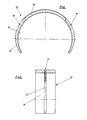
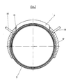
- the wound washer 5 is inserted into a saddle part, which is shown in Fig. 4 in a front view in section represents is.
- the saddle part 12 encloses the annular disc, as shown here, to a extent that is greater than 180 °.
- the washer is inserted into a groove 13 on the inner surface 14 of the saddle part, the projection 7 of the washer extending through the recess 15 of the saddle part.
- the saddle part has bores 16 and 17 indicated here, which can accommodate the free wire ends 10 and 11 when the washer is held in the saddle part, so that they protrude outwards from the saddle part.
- the saddle part 12 is shown in a side view in section.
- the same components are labeled with the same reference numbers.
- Fig. 6 the wound washer 5 and the saddle part 12 is shown in an exploded view.
- the same components are identified by the same reference numbers.
- Fig. 6 shows that in the bores 16 and 17 of the saddle part contact pins 18 and 19 can be inserted, in which the free ends 10 and 11 of the wire winding can be inserted and fastened with solder drops 22 accordingly.
- Corresponding clamps of a welding unit can be connected to the contact pins.
- Fig. 7 shows a sectional view through a composite welding element, which consists of the washer 5 and the saddle part 12, wherein the projection 7 of the washer protrudes through the recess 15 in the saddle part.
- a heated welding bar can be pressed onto the edge of the projection 7 protruding from the recess 15, which plasticizes and broadly presses the edge, so that there is a firm connection between the washer and the saddle part.
- Fig. 7 also shows the arrangement of the contact pins 18 and 19, by means of which the connection of the heating wire winding on the washer 5 is ensured with a welding unit.
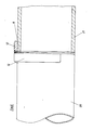
- the welding element designed in this way can, as shown in FIG. 8 is shown, are placed on two flush, butt-butted tubes 20 and 21.
- the washer 5 extends into the joint between the abutting pipe ends.
- the saddle part 12 fixes the pipe ends in the end position necessary for the welding.
- the welding element can remain on the pipe string after welding the pipe ends. However, measures can also be taken to release the connection between the saddle part and the ring disk melted by the welding process, so that the saddle part can be removed.
- the saddle part can also be made of other material, so that reuse is possible if necessary.
- the washer must in any case consist of weldable or heat-plastifiable material which can connect the pipe ends to be welded together.
Landscapes
- Engineering & Computer Science (AREA)
- Mechanical Engineering (AREA)
- General Engineering & Computer Science (AREA)
- Lining Or Joining Of Plastics Or The Like (AREA)
- Branch Pipes, Bends, And The Like (AREA)
Priority Applications (1)
| Application Number | Priority Date | Filing Date | Title |
|---|---|---|---|
| AT87103165T ATE95113T1 (de) | 1986-04-04 | 1987-03-05 | Schweisselement zum verschweissen stumpfgestossener rohre aus kunststoff. |
Applications Claiming Priority (2)
| Application Number | Priority Date | Filing Date | Title |
|---|---|---|---|
| DE3611192 | 1986-04-04 | ||
| DE19863611192 DE3611192A1 (de) | 1986-04-04 | 1986-04-04 | Verfahren zum verschweissen stumpfgestossener rohre aus kunststoff und schweisselement zur durchfuehrung des verfahrens |
Publications (3)
| Publication Number | Publication Date |
|---|---|
| EP0240732A2 true EP0240732A2 (fr) | 1987-10-14 |
| EP0240732A3 EP0240732A3 (en) | 1990-01-31 |
| EP0240732B1 EP0240732B1 (fr) | 1993-09-29 |
Family
ID=6297846
Family Applications (1)
| Application Number | Title | Priority Date | Filing Date |
|---|---|---|---|
| EP87103165A Expired - Lifetime EP0240732B1 (fr) | 1986-04-04 | 1987-03-05 | Elément de soudage pour le soudage bout à bout de tuyaux en matière plastique |
Country Status (6)
| Country | Link |
|---|---|
| US (1) | US4851647A (fr) |
| EP (1) | EP0240732B1 (fr) |
| JP (1) | JPS631526A (fr) |
| AT (1) | ATE95113T1 (fr) |
| DE (2) | DE3611192A1 (fr) |
| ES (1) | ES2047479T3 (fr) |
Cited By (2)
| Publication number | Priority date | Publication date | Assignee | Title |
|---|---|---|---|---|
| EP0382971B1 (fr) * | 1989-02-13 | 1993-09-15 | Uponor Bv | Coude de tuyau ajustable avec dispositif à soudage électrique |
| FR2693145A1 (fr) * | 1992-07-02 | 1994-01-07 | Fischer Georg Rohrleitung | Procédé de soudage de pièces de forme tubulaire et élément de soudage pour la mise en Óoeuvre du procédé. |
Families Citing this family (13)
| Publication number | Priority date | Publication date | Assignee | Title |
|---|---|---|---|---|
| NL8403462A (nl) * | 1984-11-13 | 1986-06-02 | Arie De Jong | Werkwijze voor het vervaardigen van een verbindingsvormstuk, in het bijzonder aanboorzadel en een volgens de werkwijze vervaardigd verbindingsvormstuk. |
| US5104468A (en) * | 1984-11-13 | 1992-04-14 | Riesselmann & Sohn | Method of producing a molded connection piece and method for joining tube with molded connection piece |
| US5407514A (en) * | 1988-02-03 | 1995-04-18 | E. O. Butts Consultants Ltd. | Method for welding thermoplastic materials |
| JPH01124475U (fr) * | 1988-02-17 | 1989-08-24 | ||
| US5494318A (en) * | 1993-04-29 | 1996-02-27 | Butts; Nicholas E. | Secondary containment system |
| GB2284179A (en) * | 1993-11-30 | 1995-05-31 | Uponor Aldyl Ltd | Electrofusion coupling element |
| EP0927097A1 (fr) * | 1995-06-28 | 1999-07-07 | Raymond Allan Goldsmid | Element destine au soudage par fusion de plastiques |
| GB2304073B (en) * | 1995-08-04 | 1999-06-16 | Uponor Ltd | Electrofusion element |
| US5736715A (en) * | 1996-03-19 | 1998-04-07 | Thermacor Process, Inc. | Method of forming pressure testable joint between insulated pipes using split sleeve arrangement |
| US6142483A (en) * | 1998-09-21 | 2000-11-07 | The United States Of America As Represented By The Administrator Of The National Aeronautics And Space Administration | Gasket assembly for sealing mating surfaces |
| AU2002348380A1 (en) * | 2001-10-22 | 2003-05-06 | Compagnie Plastic Omnium Corp. | Welded, plastic flange connection |
| DE102004023338A1 (de) * | 2004-05-12 | 2005-12-15 | Gwc Gas-Water-Valves-Components Gmbh | Heizvorrichtung zum Verschweißen von mindestens zwei aus einem Kunststoffmaterial bestehenden Gegenständen |
| US8741091B2 (en) * | 2012-04-26 | 2014-06-03 | Richard Hardy | Method for thermoplastic welding and welded composite structures |
Family Cites Families (16)
| Publication number | Priority date | Publication date | Assignee | Title |
|---|---|---|---|---|
| DD1161A (fr) * | ||||
| DE7121715U (de) * | 1971-09-02 | Mannesmann Ag | Widerstandsheizelement zum Ver schweißen von Gegenstanden aus thermo plastischem Kunststoff | |
| US2744655A (en) * | 1953-09-22 | 1956-05-08 | Vnuk Josef | Lined container and closure therefor |
| DE1055305B (de) * | 1954-05-26 | 1959-04-16 | Ramsay Olaf St George | Verbindungsteil aus thermoplastischem Material in Form einer Muffe, eines T-Stueckesoder L-Stueckes |
| CH336980A (de) * | 1955-09-16 | 1959-03-15 | Fischer Ag Georg | Verfahren zum Zusammenschweissen von Rohrleitungselementen aus Kunststoff |
| US3378672A (en) * | 1966-03-18 | 1968-04-16 | Susquehanna Corp | Insulated, electrical resistance wire and welding sleeve made therefrom |
| DE1629221B2 (de) * | 1966-06-10 | 1972-12-21 | Wegener, Willy, Dipl.-Ing., 5100 Aachen | Schweißspiegel zum Stumpfschweißen von Rohren und Behältern aus thermoplastischem Kunststoff |
| CH507081A (de) * | 1969-04-09 | 1971-05-15 | Gebert & Cie | Verbindungsmuffe zum Verschweissen von Kunststoffrohren |
| JPS5150375A (fr) * | 1974-10-30 | 1976-05-01 | Furukawa Electric Co Ltd | |
| FR2353381A1 (fr) * | 1976-06-03 | 1977-12-30 | Pont A Mousson | Procede d'assemblage par soudure de tubes plastiques et raccord pour un tel assemblage |
| US4313053A (en) * | 1980-01-02 | 1982-01-26 | Von Roll A.G. | Welding sleeve of thermoplastic material |
| MC1446A1 (fr) * | 1981-07-01 | 1982-12-06 | Innovation Tech Innotec | Derivation electrosoudable pour canalisation en materiau thermoplastique |
| FR2519578A1 (fr) * | 1981-07-01 | 1983-07-18 | Sam Innovation Tech | Dispositif en matiere plastique pour realiser une perforation dans un element sous-jacent en matiere plastique, procede de fabrication d'un tel dispositif et sa mise en oeuvre pour realiser des derivations de canalisations |
| GB8410765D0 (en) * | 1984-04-27 | 1984-06-06 | Glynwed Tubes & Fittings | Fusion pad |
| EP0170844B1 (fr) * | 1984-08-08 | 1988-01-20 | Georg Fischer Aktiengesellschaft | Pièce de piquage en matière plastique soudable |
| US4689108A (en) * | 1985-11-04 | 1987-08-25 | Gte Government Systems Corporation | Apparatus for assembling electrochemical batteries and similar articles |
-
1986
- 1986-04-04 DE DE19863611192 patent/DE3611192A1/de not_active Ceased
-
1987
- 1987-03-05 AT AT87103165T patent/ATE95113T1/de not_active IP Right Cessation
- 1987-03-05 ES ES87103165T patent/ES2047479T3/es not_active Expired - Lifetime
- 1987-03-05 DE DE87103165T patent/DE3787557D1/de not_active Expired - Fee Related
- 1987-03-05 EP EP87103165A patent/EP0240732B1/fr not_active Expired - Lifetime
- 1987-04-02 JP JP62079842A patent/JPS631526A/ja active Pending
-
1988
- 1988-08-01 US US07/226,545 patent/US4851647A/en not_active Expired - Fee Related
Cited By (3)
| Publication number | Priority date | Publication date | Assignee | Title |
|---|---|---|---|---|
| EP0382971B1 (fr) * | 1989-02-13 | 1993-09-15 | Uponor Bv | Coude de tuyau ajustable avec dispositif à soudage électrique |
| FR2693145A1 (fr) * | 1992-07-02 | 1994-01-07 | Fischer Georg Rohrleitung | Procédé de soudage de pièces de forme tubulaire et élément de soudage pour la mise en Óoeuvre du procédé. |
| DE4224680A1 (de) * | 1992-07-02 | 1994-01-27 | Fischer Georg Rohrleitung | Verfahren zum Verschweissen von rohrförmigen Teilen und ein Schweisselement zur Durchführung des Verfahrens |
Also Published As
| Publication number | Publication date |
|---|---|
| JPS631526A (ja) | 1988-01-06 |
| DE3611192A1 (de) | 1987-10-15 |
| EP0240732B1 (fr) | 1993-09-29 |
| ES2047479T3 (es) | 1994-03-01 |
| US4851647A (en) | 1989-07-25 |
| ATE95113T1 (de) | 1993-10-15 |
| DE3787557D1 (de) | 1993-11-04 |
| EP0240732A3 (en) | 1990-01-31 |
Similar Documents
| Publication | Publication Date | Title |
|---|---|---|
| DE69021955T2 (de) | Verfahren und Vorrichtung zur gegenseitigen Verbindung von Rohren. | |
| DE2724981C3 (de) | Schweißring zur Verbindung von Kunststoff rohren | |
| EP0240732B1 (fr) | Elément de soudage pour le soudage bout à bout de tuyaux en matière plastique | |
| EP0076460B1 (fr) | Liaison de soudage pour tuyaux en matière plastique | |
| EP0170845B1 (fr) | Foret de perforation pour jonction d'un branchement sur un tuyau | |
| DE2208862B2 (de) | Elektrisch schweißbarer Anbohrsattel aus thermoplastischem Werkstoff | |
| EP2159037A1 (fr) | Elément de raccordement ou de séparation destiné au raccordement à une section de tuyau par le procédé de rayonnement laser ainsi que tête laser et procédé de raccordement | |
| EP0689931A2 (fr) | Procédé pour le soudage de tuyau en matière plastique et raccord pour sa réalisation | |
| DE1908888A1 (de) | Rohrverbindung und Verfahren zu ihrer Herstellung | |
| EP1756464B1 (fr) | Systeme de liaison, en particulier pour l'assemblage par liaison de force d'au moins une piece structurale composite a base de fibres a une autre piece structurale | |
| DE3636891A1 (de) | Verfahren und vorrichtung zum stumpfschweissen von kunststoff-rohrabschnitten oder kunststoff-formstuecken | |
| DE4441373C2 (de) | Rohrverbindung, insbesondere für Rohre mit mindestens einer Kunststoffschicht | |
| EP0093328A1 (fr) | Pièce d'embranchement | |
| DE3615947C1 (en) | Welding and centring ring | |
| EP3271138B1 (fr) | Manchon de raccordement à induction | |
| DE4224680A1 (de) | Verfahren zum Verschweissen von rohrförmigen Teilen und ein Schweisselement zur Durchführung des Verfahrens | |
| EP1752699A2 (fr) | Couplage de ligne entre un raccord et un tuyau composite et un procédé de production du couplage de ligne | |
| EP3298316B1 (fr) | Raccord à brides pour éléments en matière plastique, en particulier pour éléments tubulaires en matière plastique | |
| DE9107311U1 (de) | Schweißmuffe | |
| EP1506834A1 (fr) | Méthode, dispositif de soudage et matériau de soudage pour souder un joint entre deux pièces, en particulier pour un appareil de mesure de niveau | |
| DE19612279C2 (de) | Gehäuse, insbesondere Fassungsgehäuse für Glühlampen mit Schraubsockel sowie Verfahren zur Herstellung eines derartigen Gehäuses und Vorrichtungen zur Durchführung des Verfahrens | |
| DE3708705A1 (de) | Verfahren und vorrichtung zum verschweissen rohrfoermiger kunststoffteile | |
| DE4136349C2 (de) | Schweißvorrichtung für Kunststoffrohre | |
| EP1927806A1 (fr) | Dispositif destiné à relier deux tuyaux | |
| AT392149B (de) | Verfahren zum verbinden isolierter leitungsrohre |
Legal Events
| Date | Code | Title | Description |
|---|---|---|---|
| PUAI | Public reference made under article 153(3) epc to a published international application that has entered the european phase |
Free format text: ORIGINAL CODE: 0009012 |
|
| AK | Designated contracting states |
Kind code of ref document: A2 Designated state(s): AT BE CH DE ES FR GB GR IT LI LU NL SE |
|
| PUAL | Search report despatched |
Free format text: ORIGINAL CODE: 0009013 |
|
| AK | Designated contracting states |
Kind code of ref document: A3 Designated state(s): AT BE CH DE ES FR GB GR IT LI LU NL SE |
|
| 17P | Request for examination filed |
Effective date: 19900613 |
|
| 17Q | First examination report despatched |
Effective date: 19910610 |
|
| GRAA | (expected) grant |
Free format text: ORIGINAL CODE: 0009210 |
|
| AK | Designated contracting states |
Kind code of ref document: B1 Designated state(s): AT BE CH DE ES FR GB GR IT LI LU NL SE |
|
| REF | Corresponds to: |
Ref document number: 95113 Country of ref document: AT Date of ref document: 19931015 Kind code of ref document: T |
|
| REF | Corresponds to: |
Ref document number: 3787557 Country of ref document: DE Date of ref document: 19931104 |
|
| ITF | It: translation for a ep patent filed | ||
| ET | Fr: translation filed | ||
| GBT | Gb: translation of ep patent filed (gb section 77(6)(a)/1977) |
Effective date: 19940113 |
|
| REG | Reference to a national code |
Ref country code: GR Ref legal event code: FG4A Free format text: 3010319 |
|
| REG | Reference to a national code |
Ref country code: ES Ref legal event code: FG2A Ref document number: 2047479 Country of ref document: ES Kind code of ref document: T3 |
|
| PGFP | Annual fee paid to national office [announced via postgrant information from national office to epo] |
Ref country code: NL Payment date: 19940331 Year of fee payment: 8 Ref country code: LU Payment date: 19940331 Year of fee payment: 8 Ref country code: GB Payment date: 19940331 Year of fee payment: 8 Ref country code: FR Payment date: 19940331 Year of fee payment: 8 Ref country code: AT Payment date: 19940331 Year of fee payment: 8 |
|
| PGFP | Annual fee paid to national office [announced via postgrant information from national office to epo] |
Ref country code: BE Payment date: 19940401 Year of fee payment: 8 |
|
| PGFP | Annual fee paid to national office [announced via postgrant information from national office to epo] |
Ref country code: SE Payment date: 19940406 Year of fee payment: 8 |
|
| PGFP | Annual fee paid to national office [announced via postgrant information from national office to epo] |
Ref country code: DE Payment date: 19940412 Year of fee payment: 8 |
|
| PGFP | Annual fee paid to national office [announced via postgrant information from national office to epo] |
Ref country code: ES Payment date: 19940418 Year of fee payment: 8 |
|
| PGFP | Annual fee paid to national office [announced via postgrant information from national office to epo] |
Ref country code: GR Payment date: 19940427 Year of fee payment: 8 |
|
| PGFP | Annual fee paid to national office [announced via postgrant information from national office to epo] |
Ref country code: CH Payment date: 19940503 Year of fee payment: 8 |
|
| EPTA | Lu: last paid annual fee | ||
| PLBE | No opposition filed within time limit |
Free format text: ORIGINAL CODE: 0009261 |
|
| STAA | Information on the status of an ep patent application or granted ep patent |
Free format text: STATUS: NO OPPOSITION FILED WITHIN TIME LIMIT |
|
| 26N | No opposition filed | ||
| EAL | Se: european patent in force in sweden |
Ref document number: 87103165.4 |
|
| PG25 | Lapsed in a contracting state [announced via postgrant information from national office to epo] |
Ref country code: LU Free format text: LAPSE BECAUSE OF NON-PAYMENT OF DUE FEES Effective date: 19950305 Ref country code: GB Effective date: 19950305 Ref country code: AT Effective date: 19950305 |
|
| PG25 | Lapsed in a contracting state [announced via postgrant information from national office to epo] |
Ref country code: SE Effective date: 19950306 Ref country code: ES Free format text: LAPSE BECAUSE OF NON-PAYMENT OF DUE FEES Effective date: 19950306 |
|
| PG25 | Lapsed in a contracting state [announced via postgrant information from national office to epo] |
Ref country code: LI Effective date: 19950331 Ref country code: CH Effective date: 19950331 Ref country code: BE Effective date: 19950331 |
|
| BERE | Be: lapsed |
Owner name: RIESSELMANN & SOHN Effective date: 19950331 |
|
| PG25 | Lapsed in a contracting state [announced via postgrant information from national office to epo] |
Ref country code: GR Free format text: THE PATENT HAS BEEN ANNULLED BY A DECISION OF A NATIONAL AUTHORITY Effective date: 19950930 |
|
| PG25 | Lapsed in a contracting state [announced via postgrant information from national office to epo] |
Ref country code: NL Effective date: 19951001 |
|
| GBPC | Gb: european patent ceased through non-payment of renewal fee |
Effective date: 19950305 |
|
| PG25 | Lapsed in a contracting state [announced via postgrant information from national office to epo] |
Ref country code: FR Free format text: LAPSE BECAUSE OF NON-PAYMENT OF DUE FEES Effective date: 19951130 |
|
| REG | Reference to a national code |
Ref country code: CH Ref legal event code: PL Ref country code: GR Ref legal event code: MM2A Free format text: 3010319 |
|
| NLV4 | Nl: lapsed or anulled due to non-payment of the annual fee |
Effective date: 19951001 |
|
| PG25 | Lapsed in a contracting state [announced via postgrant information from national office to epo] |
Ref country code: DE Effective date: 19951201 |
|
| EUG | Se: european patent has lapsed |
Ref document number: 87103165.4 |
|
| REG | Reference to a national code |
Ref country code: FR Ref legal event code: ST |
|
| REG | Reference to a national code |
Ref country code: ES Ref legal event code: FD2A Effective date: 19990201 |
|
| PG25 | Lapsed in a contracting state [announced via postgrant information from national office to epo] |
Ref country code: IT Free format text: LAPSE BECAUSE OF NON-PAYMENT OF DUE FEES;WARNING: LAPSES OF ITALIAN PATENTS WITH EFFECTIVE DATE BEFORE 2007 MAY HAVE OCCURRED AT ANY TIME BEFORE 2007. THE CORRECT EFFECTIVE DATE MAY BE DIFFERENT FROM THE ONE RECORDED. Effective date: 20050305 |