EP0240779A1 - Dispositif pour superposer des matériaux laminaires - Google Patents
Dispositif pour superposer des matériaux laminaires Download PDFInfo
- Publication number
- EP0240779A1 EP0240779A1 EP87103826A EP87103826A EP0240779A1 EP 0240779 A1 EP0240779 A1 EP 0240779A1 EP 87103826 A EP87103826 A EP 87103826A EP 87103826 A EP87103826 A EP 87103826A EP 0240779 A1 EP0240779 A1 EP 0240779A1
- Authority
- EP
- European Patent Office
- Prior art keywords
- workpiece
- stations
- stack
- station
- arrangement according
- Prior art date
- Legal status (The legal status is an assumption and is not a legal conclusion. Google has not performed a legal analysis and makes no representation as to the accuracy of the status listed.)
- Granted
Links
- 238000003860 storage Methods 0.000 claims description 18
- 238000000151 deposition Methods 0.000 claims description 7
- 238000007664 blowing Methods 0.000 claims description 5
- 239000004809 Teflon Substances 0.000 claims description 3
- 229920006362 Teflon® Polymers 0.000 claims description 3
- 238000006073 displacement reaction Methods 0.000 claims 1
- 238000004519 manufacturing process Methods 0.000 abstract description 7
- 239000004744 fabric Substances 0.000 abstract description 4
- 238000000926 separation method Methods 0.000 description 3
- 238000000034 method Methods 0.000 description 2
- 230000008569 process Effects 0.000 description 2
- 229910000831 Steel Inorganic materials 0.000 description 1
- 230000009471 action Effects 0.000 description 1
- 230000004913 activation Effects 0.000 description 1
- 239000000853 adhesive Substances 0.000 description 1
- 230000001070 adhesive effect Effects 0.000 description 1
- 239000002390 adhesive tape Substances 0.000 description 1
- 230000008859 change Effects 0.000 description 1
- 235000009508 confectionery Nutrition 0.000 description 1
- 230000000694 effects Effects 0.000 description 1
- 239000000463 material Substances 0.000 description 1
- 239000004033 plastic Substances 0.000 description 1
- 239000010959 steel Substances 0.000 description 1
- 230000007704 transition Effects 0.000 description 1
Images
Classifications
-
- D—TEXTILES; PAPER
- D05—SEWING; EMBROIDERING; TUFTING
- D05B—SEWING
- D05B33/00—Devices incorporated in sewing machines for supplying or removing the work
- D05B33/02—Devices incorporated in sewing machines for supplying or removing the work and connected, for synchronous operation, with the work-feeding devices of the sewing machine
Definitions
- the invention relates to an arrangement for superimposing two and more flat workpieces stacked in magazine stations designed as lifting tables in a predetermined mutual position on the laying table of a depositing station with the aid of a device for separating stacked workpieces and of traversing means for successively removing the workpieces from the Magazine stations and for positioned storage on the laying table of the storage station.
- the invention has for its object to provide a further solution for an arrangement for the automatic folding of flat workpieces of the type described in the introduction, which manages during transition from one batch of workpieces to another batch of workpieces of different sizes and shapes with extremely short changeover times and thus the use of such arrangements, particularly in the manufacture of ready-made clothing, is significantly increased in their efficiency.
- the invention is based on the essential finding that when a workpiece is separated from the workpiece stack, it is entirely sufficient to lift the workpiece to be separated on one side, in order then to use this opening gap to pull this workpiece by means of a film-like carrier with a slidable surface texture, for example a Teflon film, which may be tensioned between the workpiece to be separated and the workpiece stack from the workpiece stack sort of peel it off.
- a film-like carrier with a slidable surface texture for example a Teflon film
- separating devices such as are described, for example, in the cited reference DE 33364226 A1
- a workpiece is separated from the workpiece stack by completely lifting this workpiece with the aid of a larger number of workpiece grippers, which grip the workpiece evenly on the circumference and in the central region of this workpiece.
- most of the workpiece grippers usually have to be realigned with regard to the contour surface now available, which is time-consuming .
- the simple reciprocating movement of the carrier between the magazine stations and the depositing station enables a depositing process to be carried out much more quickly than is possible with a conventional lifting device attached to a carriage.
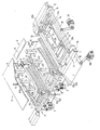
- the single figure shown in the drawing shows a perspective view of a preferred embodiment of the arrangement according to the invention with two magazine stations and a storage station, which are arranged in a row one behind the other.
- a and B represent two magazine stations and C the storage station.
- Each of the magazine stations A and B has a lifting table 1 with a spindle gear 2 for height adjustment, on each of which there is a workpiece stack 3 with three partial stacks 31, 32 and 33.
- the partial stacks 31, 32 and 33 are each arranged one above the other in terms of their size such that the smallest partial stack 33 is the uppermost partial stack.
- the magazine stations A and B have a separating device above the lifting table 1 and above the workpiece stacks 3 placed thereon.
- This separating device 4 consists of a lifting plate 6 which is adjustable in the vertical direction on a lifting cylinder 5 and on the underside of which finger-shaped workpiece grippers 61, 62 and 63 are arranged.
- the workpiece grippers 61, 62 and 63 are arranged on the lifting plate 6 so that they are aligned along the edge of the workpieces of the workpiece stack 3 on the side of the storage station C.
- the spindle drive 2 of the magazine stations A and B is controlled in each case by a light switch 7 so that the uppermost workpiece of the workpiece stack 3 is always in a predetermined removal level regardless of the height of the workpiece stack.
- two blowing nozzles 8 are also provided on the rear of the lifting table 1 of the magazine stations A and B, the air flow of which supports the separation process when carrying out a separation of a workpiece from the workpiece stack 3.
- the partial stacks 31, 32 and 33 are stacked one above the other in such a way that they each abut together with a contour edge on the stop 9 in the form of a strip at the rear edge of the lifting table 1.
- the workpiece gripper 63 which is furthest away from this stop 9, is adjustably arranged on the lifting plate 6 via a drive 63a.
- a light sensor 63b is additionally assigned to the workpiece gripper 63 for controlling the drive 63a net, which causes a shift of the workpiece gripper 63 forward when changing from one partial stack to the next until its light beam directed downward onto the workpiece stack 3 is reflected.
- each of the partial stacks 31, 32 and 33 is covered from above with a template 31a or 32a which is adapted to the contour surface of the workpieces of this partial stack and which has a light-reflecting partial surface 30 in on its top side below the adjustable workpiece gripper 63 Has the shape of a glued reflective film.
- the uppermost partial stack 33 which has already been partially processed, understandably does not show the template originally covering this partial stack 33.
- the storage station C has a conveyor belt 10 as a storage table, which is oriented perpendicular to the row of stations in its conveying direction.
- a sliding frame 12 is fastened in the vertical direction on a mounting frame, not shown, to the lifting cylinders 11 above the conveyor belt 10.
- three light sensors 13 are fixedly mounted in a suitable mutual arrangement on this mounting frame for controlling the positioning of the workpieces to be placed on the conveyor belt, the light beam of which is oriented downward onto the laying table.
- the sliding frame 12 also has drives 14 and 15 controlled by the light sensors 13 for its sliding movement in the direction of the row of stations arranged one behind the other and in the direction perpendicular thereto.
- an endless drive belt 17 guided over deflection rollers 16 is provided on each side. Both drive belts 17 are moved together by a drive 19 via a shaft 18 connecting the deflection rollers 16. Between these two drive belts 17, brackets 20 of the carrier 21 span the entire width of the stations, specifically in the removal plane in the area of the magazine sta tion A and B fixing height. In this way, the film-like carrier 21 can be moved between the different stations. It has the light-reflecting partial surfaces 21a, 21b and 21c required for the control of the drives 14 and 15 of the sliding frame 12 by the light sensors 13, which are in their travel position above the conveyor belt 10 in the region of the light beams of these light sensors 13.
- the workpiece stack 3 on the magazine station A consists of jacket outer fabric parts which have been cut in the usual way so that the same fabric sides lie on top of one another in the case of successive workpieces in the stack.
- the same is said to apply to the workpiece stack 3 on the magazine station B, which consists of inserts corresponding to the outer material parts on the magazine station A.
- the template covering the uppermost partial stack 33, on the light-reflecting partial surface of which the light scanner 63b of the workpiece gripper 63 has been oriented for controlling the setting of this workpiece gripper, has already been removed on both magazine stations A and B.
- the now uppermost workpiece on the partial stack 33 lies on the magazine station A with its outside of the fabric facing downward and on the magazine station B with its side having the adhesive dot grid facing upward.
- the carrier 21 is now moved over the magazine station B to the magazine station A.
- the uppermost workpiece is gripped and lowered on the workpiece stack 3 by lowering the lifting plate 6 with its workpiece grippers 61, 62 and 63 gripped edge with simultaneous activation of the blowing nozzles 8 by re-raising the lifting plate 6, an opening slot is created between this workpiece and the workpiece stack for the carrier 21.
- the carrier 21 moves into this opening slot up to its end position above the magazine station A and thereby peels off this workpiece from the workpiece stack.
- the lifting plate 6 with the workpiece grippers 61, 62 and 63 moves down again.
- the workpiece grippers 61, 62 and 63 are released from the workpiece under pressure on the peeled workpiece on the carrier 21.
- the lifting plate 6 then moves upward again with the workpiece grippers 61, 62 and 63.
- the carrier 21 then moves with the workpiece separated from the workpiece stack 3 into its end position on the right-hand side above the conveyor belt 10 of the storage station C.
- the sliding frame 12 lowers onto the workpiece and depending on the control of the light scanners 13, in cooperation with the light-reflecting partial surfaces 21a, 21b and 21c, it moves into the predetermined position.
- the lifting plate 6 of the magazine station B lowers with its workpiece grippers 61, 62 and 63 onto the workpiece stack 3 which represents the insert parts and then lifts the uppermost workpiece on the side of the storage station C with simultaneous action of the blowing air of the blowing nozzles 8.
- the carrier 21 By moving the carrier 21 towards the magazine station B again, the workpiece held on the underside of the sliding frame is stripped from the carrier 21 and placed on the conveyor belt 10 in the held position.
- the sliding frame 12 then moves back into its raised starting position.
- the carrier 21 in turn moves into the slot opening between the raised workpiece and the rest of the workpiece stack 3 and now peels off this workpiece, which represents an insert part, from the workpiece stack 3.
- the carrier 21 moves the workpiece again over the conveyor belt 10 of the storage station C and play with the sliding frame 12 begins anew.
- the insert 21 is then used to first pick up an insert part from the workpiece stack 3 of the magazine station B and finally a workpiece from the magazine station A and in the predetermined position in each case is deposited exactly over the workpiece underneath.
- the sandwich that has been folded in this way is now, while the carrier 21 is again traveling to the magazine station A, to bring the first workpiece for the folding of another sandwich, via the conveyor belt 10 to the next processing station, which can be a hand station, for example, for further laying work to make this sandwich.
- the adjustable workpiece gripper 33 orients itself on the template 32a in connection with the light-reflecting partial surface 30 on the new partial stack 32 in such a way that it is displaced in the forward direction as long until the light scanner receives its own reflected light.
- the templates are then removed in the same way as the workpieces, placed on top of each other on the conveyor belt and then removed at the next work station.
- the finger-shaped workpiece grippers 61, 62 and 63 are expediently designed as adhesive tape pickups, as are described in detail in the literature reference DE 3336426 A1.
- the film-like carrier 21 can be designed quite differently.
- a stretched film for example a Teflon film, it can also consist of a thin steel sheet or a thin elastic single or multi-layer plastic plate.
- the conveyor belt 10 is aligned perpendicular to the direction of travel of the film-like carrier 21.
- the arrangement of the conveyor belt can also be carried out so that its conveying direction is in the direction of travel of the carrier 21.
- the arrangement according to the invention can advantageously be used wherever flat in the course of manufacture Workpieces are to be stored automatically one above the other and when processing batches of different sizes and shapes in small numbers, particularly short machine changeover times are important for the efficient use of such arrangements.
- the preferred area of application is the production of men's and women's outer clothing.
Landscapes
- Engineering & Computer Science (AREA)
- Textile Engineering (AREA)
- Sheets, Magazines, And Separation Thereof (AREA)
- Sewing Machines And Sewing (AREA)
- Stacking Of Articles And Auxiliary Devices (AREA)
- Collation Of Sheets And Webs (AREA)
- Polishing Bodies And Polishing Tools (AREA)
- Table Devices Or Equipment (AREA)
- Press Drives And Press Lines (AREA)
Priority Applications (1)
| Application Number | Priority Date | Filing Date | Title |
|---|---|---|---|
| AT87103826T ATE44985T1 (de) | 1986-03-27 | 1987-03-17 | Anordnung zum zusammenlegen von flaechigen werkstuecken. |
Applications Claiming Priority (2)
| Application Number | Priority Date | Filing Date | Title |
|---|---|---|---|
| DE19863610483 DE3610483A1 (de) | 1986-03-27 | 1986-03-27 | Anordnung zum zusammenlegen von flaechigen werkstuecken |
| DE3610483 | 1986-03-27 |
Publications (2)
| Publication Number | Publication Date |
|---|---|
| EP0240779A1 true EP0240779A1 (fr) | 1987-10-14 |
| EP0240779B1 EP0240779B1 (fr) | 1989-07-26 |
Family
ID=6297454
Family Applications (1)
| Application Number | Title | Priority Date | Filing Date |
|---|---|---|---|
| EP87103826A Expired EP0240779B1 (fr) | 1986-03-27 | 1987-03-17 | Dispositif pour superposer des matériaux laminaires |
Country Status (6)
| Country | Link |
|---|---|
| US (1) | US4753428A (fr) |
| EP (1) | EP0240779B1 (fr) |
| JP (1) | JPS6312565A (fr) |
| AT (1) | ATE44985T1 (fr) |
| CA (1) | CA1295586C (fr) |
| DE (2) | DE3610483A1 (fr) |
Families Citing this family (2)
| Publication number | Priority date | Publication date | Assignee | Title |
|---|---|---|---|---|
| ITPD20120364A1 (it) * | 2012-12-05 | 2014-06-06 | Omac Srl | Macchina per la lavorazione di articoli di pelletteria |
| CN108893876B (zh) * | 2018-09-25 | 2023-10-13 | 广东溢达纺织有限公司 | 车缝定位装置及自动车缝设备 |
Citations (5)
| Publication number | Priority date | Publication date | Assignee | Title |
|---|---|---|---|---|
| US3945632A (en) * | 1973-05-22 | 1976-03-23 | Usm Corporation | Machine for assembling flexible workpieces |
| US4198041A (en) * | 1976-05-26 | 1980-04-15 | Cluett, Peabody & Co., Inc. | Method and apparatus for handling, positioning and assembling fabric plies |
| DE3218189A1 (de) * | 1982-05-14 | 1983-11-17 | Rotex Maschinen GmbH, 5600 Wuppertal | Vorrichtung zum entnehmen und ablegen von flaechenhaften teilen, insbesondere textilteilen |
| DE3336426A1 (de) * | 1983-10-06 | 1985-04-18 | Maschinenfabrik Herbert Meyer KG, 8000 München | Vorrichtung zum aufnehmen flaechiger werkstuecke |
| DE3436965A1 (de) * | 1983-11-09 | 1985-05-15 | Veb Kombinat Textima, Ddr 9010 Karl-Marx-Stadt | Verfahren und vorrichtung zum ausrichten von stueckigen flaechengebilden |
Family Cites Families (20)
| Publication number | Priority date | Publication date | Assignee | Title |
|---|---|---|---|---|
| US2006071A (en) * | 1931-07-06 | 1935-06-25 | Herbert E Edwards | Assembling machine |
| US3083961A (en) * | 1960-06-23 | 1963-04-02 | Pfaff Ag G M | Pickup device for use in feeding mechanism and the like |
| GB961371A (en) * | 1962-05-29 | 1964-06-17 | Kemp Applic Ltd | Improvements relating to sheet feeding devices |
| US3386396A (en) * | 1965-06-29 | 1968-06-04 | Jacobs Machine Corp | Combined automatic sewing assembly |
| US3664657A (en) * | 1965-07-30 | 1972-05-23 | Ivanhoe Research Corp | Methods and apparatus for automatically transfering and registering fabric workpieces and for combining them |
| US3544098A (en) * | 1965-07-30 | 1970-12-01 | Ivanhoe Research Corp | Methods and apparatus for automatically transferring and registering fabric workpieces |
| US3611957A (en) * | 1970-01-26 | 1971-10-12 | Farah Mfg Co Inc | Pocket blank forming machine |
| JPS5015265A (fr) * | 1973-05-09 | 1975-02-18 | ||
| DE2411300C2 (de) * | 1974-03-09 | 1976-04-29 | G. Siempelkamp & Co, 4150Krefeld | Einrichtung zum Zusammenlegen einer unteren Decklage, einer Mittellage und einer oberen Decklage zu einem Stapel im Zuge der Herstellung von vergüteten Trägerplatten und dgl |
| US3964953A (en) * | 1975-03-25 | 1976-06-22 | Union Camp Corporation | Apparatus and method for laminating liner to box blank |
| US4143871A (en) * | 1976-07-01 | 1979-03-13 | Levi Strauss & Company | Facing ply separator |
| JPS5545455A (en) * | 1978-09-26 | 1980-03-31 | Oji Giken Kk | Livinggbody feedback training device |
| US4343255A (en) * | 1979-05-01 | 1982-08-10 | Starkville Tool And Die Company | Automated placket shirt machine |
| FR2456691A1 (fr) * | 1979-05-18 | 1980-12-12 | Anvar | Procede de positionnement d'une piece souple en feuille sur une surface de support et installation de manutention faisant application de ce procede |
| DE3016676C2 (de) * | 1980-04-30 | 1982-06-16 | Pfaff Industriemaschinen Gmbh, 6750 Kaiserslautern | Automatische Nähanlage zum randgleichen Zusammennähen zweier Nähgutanlagen |
| JPS5725458A (en) * | 1980-07-18 | 1982-02-10 | Kanai Hiroyuki | Core fabric material |
| DE3236677A1 (de) * | 1981-11-26 | 1983-06-01 | Veb Kombinat Textima, Ddr 9010 Karl-Marx-Stadt | Verfahren und vorrichtung zum umstapeln textiler flaechengebilde |
| DE8304012U1 (de) * | 1983-02-12 | 1983-09-15 | August Wilhelm Andernach KG, 5300 Bonn | Sturzverhinderer fuer einen schraegaufzug |
| US4708333A (en) * | 1984-11-23 | 1987-11-24 | State Of Israel, Ministry Of Defense, Rafael Armament Development Authority | Method and apparatus for separating, feeding and/or folding sheets |
| US4688499A (en) * | 1986-12-01 | 1987-08-25 | Collins & Aikman Corporation | Apparatus for automatically fabricating textile articles such as bath throw rugs and the like |
-
1986
- 1986-03-27 DE DE19863610483 patent/DE3610483A1/de not_active Withdrawn
-
1987
- 1987-03-17 DE DE8787103826T patent/DE3760369D1/de not_active Expired
- 1987-03-17 EP EP87103826A patent/EP0240779B1/fr not_active Expired
- 1987-03-17 AT AT87103826T patent/ATE44985T1/de active
- 1987-03-19 US US07/027,825 patent/US4753428A/en not_active Expired - Fee Related
- 1987-03-26 CA CA000533019A patent/CA1295586C/fr not_active Expired - Fee Related
- 1987-03-27 JP JP62071958A patent/JPS6312565A/ja active Granted
Patent Citations (5)
| Publication number | Priority date | Publication date | Assignee | Title |
|---|---|---|---|---|
| US3945632A (en) * | 1973-05-22 | 1976-03-23 | Usm Corporation | Machine for assembling flexible workpieces |
| US4198041A (en) * | 1976-05-26 | 1980-04-15 | Cluett, Peabody & Co., Inc. | Method and apparatus for handling, positioning and assembling fabric plies |
| DE3218189A1 (de) * | 1982-05-14 | 1983-11-17 | Rotex Maschinen GmbH, 5600 Wuppertal | Vorrichtung zum entnehmen und ablegen von flaechenhaften teilen, insbesondere textilteilen |
| DE3336426A1 (de) * | 1983-10-06 | 1985-04-18 | Maschinenfabrik Herbert Meyer KG, 8000 München | Vorrichtung zum aufnehmen flaechiger werkstuecke |
| DE3436965A1 (de) * | 1983-11-09 | 1985-05-15 | Veb Kombinat Textima, Ddr 9010 Karl-Marx-Stadt | Verfahren und vorrichtung zum ausrichten von stueckigen flaechengebilden |
Also Published As
| Publication number | Publication date |
|---|---|
| JPS6312565A (ja) | 1988-01-19 |
| CA1295586C (fr) | 1992-02-11 |
| JPH0573667B2 (fr) | 1993-10-14 |
| DE3610483A1 (de) | 1987-10-08 |
| US4753428A (en) | 1988-06-28 |
| ATE44985T1 (de) | 1989-08-15 |
| EP0240779B1 (fr) | 1989-07-26 |
| DE3760369D1 (en) | 1989-08-31 |
Similar Documents
| Publication | Publication Date | Title |
|---|---|---|
| DE3222657A1 (de) | Einrichtung und verfahren zum automatischen montieren von teilen auf chassis | |
| DE112012006565T5 (de) | Verfahren und Vorrichtung zum Entfernen eines im Wesentlichen flachen Werkstücks von der Oberseite eines Stapels aus Werkstücken | |
| DE2906543A1 (de) | Verfahren und anlage zum sortieren von tafelfoermigem gut | |
| DE3613315C2 (fr) | ||
| EP0856396B1 (fr) | Appareil flexible pour former des découpes en carton | |
| DE2310021A1 (de) | Einrichtung zum empfangen und trennen von ausschnitten | |
| EP3344405B1 (fr) | Installation de production et procédé de fabrication de plaques d'immatriculation de véhicules automobiles | |
| EP0101025A2 (fr) | Dispositif de retournement dans une ligne de transport entre deux machines d'usinage | |
| DE19509446B4 (de) | Palette zur Zuführung von Laufstreifen an eine Reifenaufbautrommel | |
| DE2808948C2 (de) | Vorrichtung zum Aufeinanderschichten von Lagen aus Papierbogen | |
| EP0240779B1 (fr) | Dispositif pour superposer des matériaux laminaires | |
| DE2618950A1 (de) | Plattentransportmaschine | |
| DE3218189A1 (de) | Vorrichtung zum entnehmen und ablegen von flaechenhaften teilen, insbesondere textilteilen | |
| DE3841683A1 (de) | Vorrichtung zum ausschneiden und ggf. gleichzeitigen formen von teilen aus blechtafeln | |
| EP0489681B1 (fr) | Procédé et dispositif pour déplacer des pièces en forme de bandes ou de panneaux, empilés et juxtaposés sur une surface de support à faible coefficient de frottement | |
| DE4436531C1 (de) | Verfahren zum Überführen von mehrreihig aus einer thermoplastischen Kunstoffolie geformten und ausgestanzten Artikeln in einreihige Stapel und Vorrichtung zur Durchführung des Verfahrens | |
| DE2303659A1 (de) | Vorrichtung zum automatischen beund entladen von maschinen | |
| EP0741101B1 (fr) | Méthode pour séparer une pile de cahiers dans un empileur et empileur pour la mise en oeuvre de cette méthode | |
| DE4242270A1 (de) | Plattenzuführeinrichtung für Plattenaufteilsägeanlagen | |
| DE3533176A1 (de) | Verfahren und vorrichtung zum befestigen von farbauszuegen auf einem transparenten basisfilm zur herstellung von druckplatten | |
| EP4122833A1 (fr) | Installation d'emballage et procédé d'alimentation en découpes de carton | |
| DE3538528A1 (de) | Verfahren und vorrichtung zur herstellung von etikettierten kunststofformlingen | |
| EP0264940A2 (fr) | Machine pour la fabrication d'objets en deux parties | |
| DE3841727A1 (de) | Verfahren und vorrichtung zum verkleben von textilen flaechengebilden | |
| EP4086012A1 (fr) | Procédé et dispositif de tri de lamelles |
Legal Events
| Date | Code | Title | Description |
|---|---|---|---|
| PUAI | Public reference made under article 153(3) epc to a published international application that has entered the european phase |
Free format text: ORIGINAL CODE: 0009012 |
|
| AK | Designated contracting states |
Kind code of ref document: A1 Designated state(s): AT CH DE FR GB IT LI |
|
| 17P | Request for examination filed |
Effective date: 19871119 |
|
| 17Q | First examination report despatched |
Effective date: 19881219 |
|
| GRAA | (expected) grant |
Free format text: ORIGINAL CODE: 0009210 |
|
| RAP3 | Party data changed (applicant data changed or rights of an application transferred) |
Owner name: HERBERT MEYER GMBH & CO. KG |
|
| AK | Designated contracting states |
Kind code of ref document: B1 Designated state(s): AT CH DE FR GB IT LI |
|
| REF | Corresponds to: |
Ref document number: 44985 Country of ref document: AT Date of ref document: 19890815 Kind code of ref document: T |
|
| GBT | Gb: translation of ep patent filed (gb section 77(6)(a)/1977) | ||
| REF | Corresponds to: |
Ref document number: 3760369 Country of ref document: DE Date of ref document: 19890831 |
|
| ET | Fr: translation filed | ||
| ITF | It: translation for a ep patent filed | ||
| PLBE | No opposition filed within time limit |
Free format text: ORIGINAL CODE: 0009261 |
|
| STAA | Information on the status of an ep patent application or granted ep patent |
Free format text: STATUS: NO OPPOSITION FILED WITHIN TIME LIMIT |
|
| 26N | No opposition filed | ||
| ITTA | It: last paid annual fee | ||
| PGFP | Annual fee paid to national office [announced via postgrant information from national office to epo] |
Ref country code: GB Payment date: 19980218 Year of fee payment: 12 |
|
| PGFP | Annual fee paid to national office [announced via postgrant information from national office to epo] |
Ref country code: FR Payment date: 19980220 Year of fee payment: 12 |
|
| PGFP | Annual fee paid to national office [announced via postgrant information from national office to epo] |
Ref country code: AT Payment date: 19980302 Year of fee payment: 12 |
|
| PGFP | Annual fee paid to national office [announced via postgrant information from national office to epo] |
Ref country code: DE Payment date: 19980320 Year of fee payment: 12 |
|
| PGFP | Annual fee paid to national office [announced via postgrant information from national office to epo] |
Ref country code: CH Payment date: 19980522 Year of fee payment: 12 |
|
| PG25 | Lapsed in a contracting state [announced via postgrant information from national office to epo] |
Ref country code: GB Free format text: LAPSE BECAUSE OF NON-PAYMENT OF DUE FEES Effective date: 19990317 Ref country code: AT Free format text: LAPSE BECAUSE OF NON-PAYMENT OF DUE FEES Effective date: 19990317 |
|
| PG25 | Lapsed in a contracting state [announced via postgrant information from national office to epo] |
Ref country code: LI Free format text: LAPSE BECAUSE OF NON-PAYMENT OF DUE FEES Effective date: 19990331 Ref country code: CH Free format text: LAPSE BECAUSE OF NON-PAYMENT OF DUE FEES Effective date: 19990331 |
|
| GBPC | Gb: european patent ceased through non-payment of renewal fee |
Effective date: 19990317 |
|
| REG | Reference to a national code |
Ref country code: CH Ref legal event code: PL |
|
| PG25 | Lapsed in a contracting state [announced via postgrant information from national office to epo] |
Ref country code: FR Free format text: LAPSE BECAUSE OF NON-PAYMENT OF DUE FEES Effective date: 19991130 |
|
| REG | Reference to a national code |
Ref country code: FR Ref legal event code: ST |
|
| PG25 | Lapsed in a contracting state [announced via postgrant information from national office to epo] |
Ref country code: DE Free format text: LAPSE BECAUSE OF NON-PAYMENT OF DUE FEES Effective date: 20000101 |
|
| PG25 | Lapsed in a contracting state [announced via postgrant information from national office to epo] |
Ref country code: IT Free format text: LAPSE BECAUSE OF NON-PAYMENT OF DUE FEES;WARNING: LAPSES OF ITALIAN PATENTS WITH EFFECTIVE DATE BEFORE 2007 MAY HAVE OCCURRED AT ANY TIME BEFORE 2007. THE CORRECT EFFECTIVE DATE MAY BE DIFFERENT FROM THE ONE RECORDED. Effective date: 20050317 |