EP0240793A2 - Procédé de condensation pour vapeur d'eau hypoborique - Google Patents
Procédé de condensation pour vapeur d'eau hypoborique Download PDFInfo
- Publication number
- EP0240793A2 EP0240793A2 EP87103949A EP87103949A EP0240793A2 EP 0240793 A2 EP0240793 A2 EP 0240793A2 EP 87103949 A EP87103949 A EP 87103949A EP 87103949 A EP87103949 A EP 87103949A EP 0240793 A2 EP0240793 A2 EP 0240793A2
- Authority
- EP
- European Patent Office
- Prior art keywords
- water
- pump
- vacuum pump
- heat
- ring vacuum
- Prior art date
- Legal status (The legal status is an assumption and is not a legal conclusion. Google has not performed a legal analysis and makes no representation as to the accuracy of the status listed.)
- Granted
Links
- XLYOFNOQVPJJNP-UHFFFAOYSA-N water Substances O XLYOFNOQVPJJNP-UHFFFAOYSA-N 0.000 title claims abstract description 113
- 238000000034 method Methods 0.000 title claims abstract description 32
- 238000009833 condensation Methods 0.000 title claims abstract description 15
- 230000005494 condensation Effects 0.000 title claims abstract description 15
- 239000007788 liquid Substances 0.000 claims abstract description 26
- 238000010438 heat treatment Methods 0.000 claims abstract description 19
- 238000001035 drying Methods 0.000 claims abstract description 10
- 239000002918 waste heat Substances 0.000 claims abstract description 10
- 239000000463 material Substances 0.000 claims description 12
- 239000007921 spray Substances 0.000 claims description 11
- 238000001291 vacuum drying Methods 0.000 claims description 10
- 239000006096 absorbing agent Substances 0.000 claims description 5
- 238000005507 spraying Methods 0.000 claims description 5
- 239000007789 gas Substances 0.000 claims description 4
- 238000011144 upstream manufacturing Methods 0.000 claims description 3
- 239000002699 waste material Substances 0.000 claims description 2
- 238000009413 insulation Methods 0.000 abstract description 3
- 239000012530 fluid Substances 0.000 description 5
- 230000002349 favourable effect Effects 0.000 description 4
- QGZKDVFQNNGYKY-UHFFFAOYSA-N Ammonia Chemical compound N QGZKDVFQNNGYKY-UHFFFAOYSA-N 0.000 description 2
- 229920000426 Microplastic Polymers 0.000 description 1
- 229910021529 ammonia Inorganic materials 0.000 description 1
- 238000006243 chemical reaction Methods 0.000 description 1
- 238000004821 distillation Methods 0.000 description 1
- 238000005516 engineering process Methods 0.000 description 1
- 239000008187 granular material Substances 0.000 description 1
- 238000011084 recovery Methods 0.000 description 1
- 239000003507 refrigerant Substances 0.000 description 1
- 239000000126 substance Substances 0.000 description 1
- 239000002023 wood Substances 0.000 description 1
Images

Classifications
-
- F—MECHANICAL ENGINEERING; LIGHTING; HEATING; WEAPONS; BLASTING
- F26—DRYING
- F26B—DRYING SOLID MATERIALS OR OBJECTS BY REMOVING LIQUID THEREFROM
- F26B23/00—Heating arrangements
- F26B23/001—Heating arrangements using waste heat
- F26B23/002—Heating arrangements using waste heat recovered from dryer exhaust gases
-
- F—MECHANICAL ENGINEERING; LIGHTING; HEATING; WEAPONS; BLASTING
- F26—DRYING
- F26B—DRYING SOLID MATERIALS OR OBJECTS BY REMOVING LIQUID THEREFROM
- F26B17/00—Machines or apparatus for drying materials in loose, plastic, or fluidised form, e.g. granules, staple fibres, with progressive movement
- F26B17/18—Machines or apparatus for drying materials in loose, plastic, or fluidised form, e.g. granules, staple fibres, with progressive movement with movement performed by rotating helical blades or other rotary conveyors which may be heated moving materials in stationary chambers, e.g. troughs
-
- F—MECHANICAL ENGINEERING; LIGHTING; HEATING; WEAPONS; BLASTING
- F26—DRYING
- F26B—DRYING SOLID MATERIALS OR OBJECTS BY REMOVING LIQUID THEREFROM
- F26B5/00—Drying solid materials or objects by processes not involving the application of heat
- F26B5/04—Drying solid materials or objects by processes not involving the application of heat by evaporation or sublimation of moisture under reduced pressure, e.g. in a vacuum
- F26B5/041—Drying solid materials or objects by processes not involving the application of heat by evaporation or sublimation of moisture under reduced pressure, e.g. in a vacuum for drying flowable materials, e.g. suspensions, bulk goods, in a continuous operation, e.g. with locks or other air tight arrangements for charging/discharging
-
- Y—GENERAL TAGGING OF NEW TECHNOLOGICAL DEVELOPMENTS; GENERAL TAGGING OF CROSS-SECTIONAL TECHNOLOGIES SPANNING OVER SEVERAL SECTIONS OF THE IPC; TECHNICAL SUBJECTS COVERED BY FORMER USPC CROSS-REFERENCE ART COLLECTIONS [XRACs] AND DIGESTS
- Y02—TECHNOLOGIES OR APPLICATIONS FOR MITIGATION OR ADAPTATION AGAINST CLIMATE CHANGE
- Y02P—CLIMATE CHANGE MITIGATION TECHNOLOGIES IN THE PRODUCTION OR PROCESSING OF GOODS
- Y02P70/00—Climate change mitigation technologies in the production process for final industrial or consumer products
- Y02P70/10—Greenhouse gas [GHG] capture, material saving, heat recovery or other energy efficient measures, e.g. motor control, characterised by manufacturing processes, e.g. for rolling metal or metal working
Definitions
- the invention relates to a condensation method for water vapor under vacuum, which is preferably removed from a drying device, the vacuum being generated by a liquid ring vacuum pump through which a liquid flows and the steam in the liquid ring vacuum pump being condensed into the liquid flowing through it .
- condensation processes are used, for example, in vacuum drying plants, which serve to quickly and gently remove the water contained in moist material to be dried.
- DE-OS 28 2l 259 describes a vacuum drying oven for drying wood, in which condensation of the extracted water vapor takes place in accordance with the above-mentioned method. To reduce energy losses, the heat energy extracted from the water vapor is used to heat the drying oven.
- the high process complexity that is required in the known process is disadvantageous.
- two separate fluid circuits are provided, one of the circuits even carrying two different fluids with certain properties, since the different fluids, one of which is water, have to be separated again in the course of the process. To realize the The process requires a very high technical outlay.
- the solution to the first part of this object is achieved according to the invention in a method of the type mentioned at the outset in that water is used as the liquid flowing through the liquid ring vacuum pump, in that the water is conducted in a water circuit with at least one heat exchanger for heating purposes which emits heat from the water, that the circulated water before it flows into the water ring vacuum pump is passed through a waste heat of the pump and the pump drive to the water-transferring heat exchanger and that heat losses are avoided by a heat insulating housing surrounding the pump and its drive and the heat exchanger.
- the simplification of the process is essentially achieved by the reduction to a single fluid, namely water.
- the low technical effort also results from the fact that the vacuum pump also functions as a heat pump.
- the heat balance is particularly favorable due to the additional utilization of the waste heat from the pump and its drive as well as the avoidance of heat loss through the insulating housing.
- the water ring vacuum pump For applications that require a higher vacuum than can be achieved with the water ring vacuum pump, it can be operated as a backing pump with an upstream rotary vane vacuum pump or gas ring vacuum pump.
- the solution to the second part of the task namely the creation of a device for carrying out the method, is achieved by a device with a liquid ring vacuum pump with a water vapor supply line connected on the suction side, with a liquid supply line leading to the liquid ring vacuum pump and with a liquid line leading the liquid from the liquid ring -Vacuum pump-removing discharge line, which is characterized by a water ring-carrying water ring vacuum pump, by at least one connected between the water discharge line and the water supply line, heat from the circulated water for heating purposes, by waste heat from the pump and the pump drive the water transferring, before the pump into the water guide line switched on heat exchanger and by a heat-insulated housing with line bushings surrounding the pump with its drive.
- a device designed in this way requires little technical effort and, because of its simplicity, ensures reliable operation with a very favorable heat balance.
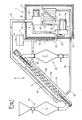
- the illustrated embodiment of the device 1 according to the invention which is combined here with a vacuum drying device 5, essentially consists of a first vacuum pump 2, a water ring vacuum pump 3 as a second vacuum pump and a heat exchanger 4.
- the first vacuum pump 2 preferably a rotary vane vacuum pump or a gas ring vacuum pump, has a steam supply line 2l which can be placed under vacuum by means of the pumps 2 and 3.
- an intermediate steam line 22 connects to the vacuum pump 2 and connects to the intake side the water ring vacuum pump 3 is connected, and in which a backing vacuum prevails.
- the water ring vacuum pump 3 has water flowing through it and therefore has a water supply line 3l and a water discharge line 33.
- the pumps 2 and 3 are each driven by a drive motor 23 and 33, which are preferably electric motors.
- the heat exchanger 4 which is switched on by means of an inlet 4l and an outlet 42 in the water supply line 3l, serves to utilize the drive waste heat.
- the two pumps 2 and 3 and the heat exchanger 4 are located within a closed housing l0 with thermal insulation ll and line bushings l3, l3 ⁇ and l3 ⁇ . As a result, heat losses to the outside are largely avoided.
- the heated air located in the interior l2 of the housing l0 is conveyed through the heat exchanger 4 by means of a fan 43 in the exemplary embodiment shown. With a corresponding arrangement, a single fan can also generate the required air movement both for the motors 23 and 33 and for the heat exchanger 4.
- the function of the device ie the sequence of the method, is as follows: Water of relatively low temperature enters the heat exchanger 4 and is preheated there by hot air generated by the pumps and their drives. The preheated water reaches the water ring vacuum pump 3 through the water supply line 3l.
- the steam supply line 2l which is under a high vacuum, brings very low pressure water vapor containing heat energy to the vacuum pump 2 and from it under slightly higher pressure through the steam intermediate line 22 to the water ring vacuum pump 3 In this, the water vapor is condensed into the water flowing through the pump, the thermal energy contained in the steam and the heat of condensation arising into the water pass over.
- the water heated in this way leaves the water ring vacuum pump 3 via the water discharge line 32 and is available for heating or heating purposes.
- a preheating and additional heating device 75 for example an electrically operated heating coil, is installed in the line 32 for preheating in the starting phase of the device and for support in the event of insufficient heat emission.
- the heating device 75 and the expansion tank 7 can also be arranged in the interior 12 of the housing 10.
- the particularly advantageous combination of the device 1 with the vacuum drying device 5 arises in particular because both the water vapor can be removed from the drying device 5 and the heated water can be usefully used therein.
- the vacuum drying device 5 provided here for combination with the device 1 according to the invention essentially consists of a feed part 5l, a conveyor tube 52 with a motor-driven screw 53 rotating therein, and a removal part 55 for batches Drying a debrisable material, such as the named granulate.
- the feed part 5l consists of a feed hopper, a shut-off valve and a storage container, the removal part correspondingly from a collecting container and a shut-off valve arranged underneath with a subsequent discharge pipe.
- the material to be dried is continuously conveyed by means of the screw through the conveying pipe into the collection container on the removal side, via line 2l by means of the device 1 inside the Conveyor tube 52 a moisture is generated in the material to be evaporated to evaporate.
- the conveyor tube 52 On its outside, the conveyor tube 52 is surrounded by a heating jacket 6, through which warm water flows. This warm water comes from the device 1 and passes via the water discharge line 32 and an inlet 62 into the water space 6l of the heating jacket 6, which is preferably provided with thermal insulation on its outside. It makes sense to run the water in countercurrent to the material to be dried. Via an outlet 63 and a return line 64, the cooled water returns to the water supply line 31 and thus into the device 1, in order to be heated there again.
- a very favorable energy balance is achieved with the device described, since both the heat dissipated with the steam from the material to be dried and the heat of condensation of the steam as well as the heat loss from the pump motors are largely recovered. Loss of heat to the environment occurs only to a very small extent.
- the auxiliary heater 75 is operated only in the start mode and when there is a particularly high heat requirement.
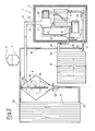
- FIG. 2 A second application example of the method according to the invention or the associated device 1 will be described with reference to FIG. 2.
- the device 1 corresponds completely to that shown in FIG. 1 and therefore need not be explained in more detail.
- the difference to Figure 1 is in the other application.
- the water vapor was removed from the material to be dried and the heated water was used to heat the material to be dried.
- the steam comes from the moisture content of the material to be dried, which is fed in from the outside.
- the application example in FIG. 2 is a completely closed system.
- the water vapor is generated here in a vacuum spray chamber 8 by spraying water by means of a spray tube 8l provided with spray nozzles 82.
- the steam passes through an outlet 83 from the spray chamber 8 via the steam supply line 2l to the device l.
- the thermal energy contained in the steam and the waste heat from the pump motors are fed to the water flowing through the water ring vacuum pump 3 in a known manner.
- the water thus heated passes through the water discharge line 32 in this example via a flow 62 ⁇ to the water space 6l ⁇ of a radiator 6 ⁇ . There, the water gives off its heat for heating purposes and, cooled by a return 63 ⁇ and a water return line 64 ⁇ , returns to the device 1 and there through the heat exchanger 4 to the water ring vacuum pump 3.
- a water branch line 84 branches off from the return line 63 ⁇ or the water return line 64 84 and leads to the spray pipe 8l in the spray chamber 8. This line replaces the evaporated amount of water withdrawn through the steam outlet 83.
- the spray chamber 8 forms part of a second circuit.
- This circuit also consists of an absorber 9, which is connected to the spray chamber 8 via an inlet 91, an outlet 92 and a water pump 93.
- the pump 93 arranged below the chamber 8 conveys the non-evaporated, precipitated water in the chamber 8 through the absorber 9, where it is heated while absorbing ambient or waste heat. From the absorber 9, the water, heated together with the water brought through the branch line 84, reaches the spray tube 81 in order to be sprayed in the spray chamber 8.
- the water vapor generated in the chamber 8 receives a comparatively high heat Energy content, which is converted in the device l in a known manner into heat energy usable for heating purposes.
- heating of the water vapor generated in chamber 8 can also be provided by means of an absorber.
- a compensating vessel 7 with a vent 7l is provided at the highest point in the water circuit in the water branch line 84.
- the vacuum pump 2 can be dispensed with. This means that the steam supply line 2l then directly with the steam intermediate line 22, i. H. is connected to the water ring vacuum pump 3, whereby a particularly simple and inexpensive embodiment of the device for performing the method according to the invention is achieved.
- FIG 3 finally shows the device of Figure 1 in a modified embodiment.
- the insulating housing 10, 11 not only the vacuum pumps 2 and 3 and the heat exchanger 4, but also, apart from the application part 5l, the vacuum drying device 5, the expansion vessel 7 and the lines 2l, 32 and 64 surrounds between the device 1 and the drying device 5.
- a particularly good heat balance is achieved in this way. Practical tests have shown that in line 32, which leads the water from device 1 to drying device 5, temperatures of up to 90 ° C. can be achieved without additional heating.
- FIG. 3 In its mode of operation, the device in FIG. 3 corresponds to the device in FIG. 1, which is why a repetition at this point is unnecessary.
- the same reference numerals in FIGS. 1 and 3 designate the same parts, so that reference is made to the description of FIG. 1 for their explanation.
Landscapes
- Engineering & Computer Science (AREA)
- Mechanical Engineering (AREA)
- General Engineering & Computer Science (AREA)
- Life Sciences & Earth Sciences (AREA)
- Sustainable Development (AREA)
- Health & Medical Sciences (AREA)
- Molecular Biology (AREA)
- Drying Of Solid Materials (AREA)
- Vaporization, Distillation, Condensation, Sublimation, And Cold Traps (AREA)
- Fuel Cell (AREA)
- Solid Thermionic Cathode (AREA)
Priority Applications (1)
| Application Number | Priority Date | Filing Date | Title |
|---|---|---|---|
| AT87103949T ATE84870T1 (de) | 1986-04-08 | 1987-03-18 | Kondensationsverfahren fuer unter unterdruck stehenden wasserdampf. |
Applications Claiming Priority (2)
| Application Number | Priority Date | Filing Date | Title |
|---|---|---|---|
| DE19863611773 DE3611773A1 (de) | 1986-04-08 | 1986-04-08 | Kondensationsverfahren fuer unter unterdruck stehenden wasserdampf |
| DE3611773 | 1986-04-08 |
Publications (3)
| Publication Number | Publication Date |
|---|---|
| EP0240793A2 true EP0240793A2 (fr) | 1987-10-14 |
| EP0240793A3 EP0240793A3 (en) | 1990-06-06 |
| EP0240793B1 EP0240793B1 (fr) | 1993-01-20 |
Family
ID=6298222
Family Applications (1)
| Application Number | Title | Priority Date | Filing Date |
|---|---|---|---|
| EP87103949A Expired - Lifetime EP0240793B1 (fr) | 1986-04-08 | 1987-03-18 | Procédé de condensation pour vapeur d'eau hypoborique |
Country Status (8)
| Country | Link |
|---|---|
| US (1) | US4753016A (fr) |
| EP (1) | EP0240793B1 (fr) |
| JP (1) | JPH0817883B2 (fr) |
| CN (1) | CN1017967B (fr) |
| AT (1) | ATE84870T1 (fr) |
| CA (1) | CA1291871C (fr) |
| DE (2) | DE3611773A1 (fr) |
| SU (1) | SU1535388A3 (fr) |
Cited By (6)
| Publication number | Priority date | Publication date | Assignee | Title |
|---|---|---|---|---|
| EP0326818A1 (fr) * | 1988-02-03 | 1989-08-09 | Maschinenfabrik Gustav Eirich | Procédé pour extraire du liquide d'un matériau humide |
| WO1990002303A1 (fr) * | 1988-08-26 | 1990-03-08 | Alex Friedmann Kg | Procede pour concentrer des substances du type boue |
| WO1995024600A1 (fr) * | 1994-03-11 | 1995-09-14 | Heinz Eichholz | Procede de sechage sous vide et disposition pour sa mise en oeuvre |
| WO1999008058A1 (fr) * | 1997-08-07 | 1999-02-18 | Solar Und Vakuum Technologie (Svt) Ag | Dispositif de sechage a vide |
| RU2276314C1 (ru) * | 2004-12-14 | 2006-05-10 | Государственное образовательное учреждение высшего профессионального образования "Орловский государственный технический университет" (ОрелГТУ) | Устройство для удаления влаги в вакууме |
| RU2328170C1 (ru) * | 2007-02-15 | 2008-07-10 | Государственное образовательное учреждение высшего профессионального образования "Орловский государственный технический университет" (ОрелГТУ) | Способ удаления влаги в вакууме |
Families Citing this family (15)
| Publication number | Priority date | Publication date | Assignee | Title |
|---|---|---|---|---|
| FI943225A0 (fi) * | 1994-07-06 | 1994-07-06 | High Speed Tech Ltd Oy | Apparatur foer undertrycktorkning av materialet skaerskild virke eller liknande |
| US5916249A (en) * | 1997-04-23 | 1999-06-29 | Baker; H. Wayne | Method and apparatus for the recovery of ammonia refrigerant |
| DE10257769A1 (de) * | 2002-12-10 | 2004-06-24 | Wagner Magnete Gmbh & Co. Kg | Verfahren zur Destillation von Flüssigkeiten mit Energierückgewinnung |
| RU2295681C2 (ru) * | 2005-05-17 | 2007-03-20 | Общество с ограниченной ответственностью "Научно-экспертное общество "ЭЛЬТРОН" | Способ и устройство энергосберегающего обезвоживания и сушки в вакууме |
| UA81138C2 (en) * | 2005-07-27 | 2007-12-10 | Bielov Oleksandr Pavlovych | Apparatus for thermo-vacuum drying |
| RU2300718C1 (ru) * | 2005-11-17 | 2007-06-10 | Общество с ограниченной ответственностью "Научно-экспертное общество "Эльтрон"" ООО "НЭО "Эльтрон"" | Устройство для низкотемпературного обезвоживания материалов в вакууме |
| WO2009135149A1 (fr) * | 2008-05-01 | 2009-11-05 | Jepson W Paul | Appareil de pompe à évaporation |
| KR101485850B1 (ko) * | 2008-09-10 | 2015-01-26 | 삼성전자 주식회사 | 의류건조기 |
| CN101671104B (zh) * | 2008-09-12 | 2011-08-17 | 王文准 | 真空沸腾污泥脱水干化方法及系统 |
| JPWO2010123010A1 (ja) * | 2009-04-21 | 2012-10-25 | 株式会社松井製作所 | プラスチック成形材料の減圧乾燥装置 |
| CN102311308B (zh) * | 2010-07-07 | 2014-01-01 | 中国石油化工股份有限公司 | 超声雾化浓缩乙醇的装置和浓缩乙醇的方法 |
| CN101922852A (zh) * | 2010-07-09 | 2010-12-22 | 丁鹏坤 | 真空干燥技术 |
| GB201603952D0 (en) * | 2016-03-08 | 2016-04-20 | Energy Recovery Systems Ltd | Methods and apparatus for treating waste |
| WO2018209419A1 (fr) * | 2017-05-16 | 2018-11-22 | Enwave Corporation | Déshydratation sous le point triple de l'eau |
| US12523424B1 (en) * | 2023-03-02 | 2026-01-13 | Forrest C. Wilkinson | Wood drying device |
Citations (1)
| Publication number | Priority date | Publication date | Assignee | Title |
|---|---|---|---|---|
| DE2821259A1 (de) | 1977-05-17 | 1978-11-23 | Vincenzo Pagnozzi | Vakuumtrockenofen |
Family Cites Families (10)
| Publication number | Priority date | Publication date | Assignee | Title |
|---|---|---|---|---|
| DE891979C (de) * | 1953-08-20 | Stuttgart-Lederberg Dipl.-Ing. Richard Schiel | Verfahren zum Betrieb von beheizten Vakuumtrocknern und Vorrichtung zu semer Durchführung | |
| US2021012A (en) * | 1932-10-27 | 1935-11-12 | Swann Res Inc | Process for production of acid alkali-metal pyrophosphates |
| US2478889A (en) * | 1942-10-29 | 1949-08-16 | Emulsol Corp | Method and apparatus for cooling hot hygroscopic solids |
| FR1161753A (fr) * | 1955-10-08 | 1958-09-04 | Installation de séchage | |
| US3392455A (en) * | 1965-11-16 | 1968-07-16 | Blaw Knox Co | Variable pressure solvent stripping system |
| US3605273A (en) * | 1970-01-16 | 1971-09-20 | Nat Distillers Chem Corp | Continuous process and apparatus for drying titanium sponge |
| HU184671B (en) * | 1979-03-21 | 1984-09-28 | Richter Gedeon Vegyeszet | Apparatus for drying and granulating wet pastelike and/or fusible materials |
| US4290269A (en) * | 1979-10-09 | 1981-09-22 | Modo-Chemetics Ab | Process for the efficient conversion of water-containing organic materials as fuels into energy |
| US4331085A (en) * | 1980-05-09 | 1982-05-25 | Tyer Robert C | Exit gas control for flame stabilization and performance tuning of starved-air auger combustor |
| FR2510736B1 (fr) * | 1981-07-28 | 1986-07-18 | Beghin Say Sa | Procede de sechage par recompression de vapeur |
-
1986
- 1986-04-08 DE DE19863611773 patent/DE3611773A1/de active Granted
-
1987
- 1987-03-18 DE DE8787103949T patent/DE3783636D1/de not_active Expired - Fee Related
- 1987-03-18 EP EP87103949A patent/EP0240793B1/fr not_active Expired - Lifetime
- 1987-03-18 AT AT87103949T patent/ATE84870T1/de not_active IP Right Cessation
- 1987-04-07 SU SU874202308A patent/SU1535388A3/ru active
- 1987-04-08 CN CN87102717A patent/CN1017967B/zh not_active Expired
- 1987-04-08 JP JP62086738A patent/JPH0817883B2/ja not_active Expired - Lifetime
- 1987-04-08 CA CA000534226A patent/CA1291871C/fr not_active Expired - Lifetime
- 1987-04-08 US US07/035,975 patent/US4753016A/en not_active Expired - Lifetime
Patent Citations (1)
| Publication number | Priority date | Publication date | Assignee | Title |
|---|---|---|---|---|
| DE2821259A1 (de) | 1977-05-17 | 1978-11-23 | Vincenzo Pagnozzi | Vakuumtrockenofen |
Non-Patent Citations (1)
| Title |
|---|
| CHEMICAL ABSTRACTS, Columbus, Ohio, US; abstract no. 132 387 |
Cited By (6)
| Publication number | Priority date | Publication date | Assignee | Title |
|---|---|---|---|---|
| EP0326818A1 (fr) * | 1988-02-03 | 1989-08-09 | Maschinenfabrik Gustav Eirich | Procédé pour extraire du liquide d'un matériau humide |
| WO1990002303A1 (fr) * | 1988-08-26 | 1990-03-08 | Alex Friedmann Kg | Procede pour concentrer des substances du type boue |
| WO1995024600A1 (fr) * | 1994-03-11 | 1995-09-14 | Heinz Eichholz | Procede de sechage sous vide et disposition pour sa mise en oeuvre |
| WO1999008058A1 (fr) * | 1997-08-07 | 1999-02-18 | Solar Und Vakuum Technologie (Svt) Ag | Dispositif de sechage a vide |
| RU2276314C1 (ru) * | 2004-12-14 | 2006-05-10 | Государственное образовательное учреждение высшего профессионального образования "Орловский государственный технический университет" (ОрелГТУ) | Устройство для удаления влаги в вакууме |
| RU2328170C1 (ru) * | 2007-02-15 | 2008-07-10 | Государственное образовательное учреждение высшего профессионального образования "Орловский государственный технический университет" (ОрелГТУ) | Способ удаления влаги в вакууме |
Also Published As
| Publication number | Publication date |
|---|---|
| CN1017967B (zh) | 1992-08-26 |
| JPS62244401A (ja) | 1987-10-24 |
| JPH0817883B2 (ja) | 1996-02-28 |
| DE3783636D1 (de) | 1993-03-04 |
| ATE84870T1 (de) | 1993-02-15 |
| CN87102717A (zh) | 1988-01-13 |
| US4753016A (en) | 1988-06-28 |
| EP0240793A3 (en) | 1990-06-06 |
| DE3611773C2 (fr) | 1988-05-11 |
| CA1291871C (fr) | 1991-11-12 |
| DE3611773A1 (de) | 1987-10-15 |
| EP0240793B1 (fr) | 1993-01-20 |
| SU1535388A3 (ru) | 1990-01-07 |
Similar Documents
| Publication | Publication Date | Title |
|---|---|---|
| EP0240793A2 (fr) | Procédé de condensation pour vapeur d'eau hypoborique | |
| EP1224021B1 (fr) | Dispositif pour le traitement de transformateurs | |
| DE3612907C2 (fr) | ||
| DE2039962A1 (de) | Verfahren und Einrichtung zur Rueckkonzentration von fluessigem Absorptionsmittel | |
| DE2311066A1 (de) | Dampferzeuger fuer ungefeuerte kraftanlage | |
| DE2929995A1 (de) | Verfahren zur umwandlung geringer waermeenergie in mechanische energie in einer turbine zur weiteren verwendung und anlage zur durchfuehrung des verfahrens | |
| DE1956956A1 (de) | Verfahren und Vorrichtung zur Frischwassererzeugung aus Seewasser | |
| DE19758184A1 (de) | Verfahren und Vorrichtung zur Dehydratation und Trocknung von Feststoff-Flüssigkeitsgemischen | |
| EP2200760B1 (fr) | Dispositif et procédé pour nettoyer des espaces fermés | |
| DE3515999A1 (de) | Vorrichtung zum konzentrieren von salzwasser | |
| DD284081A5 (de) | Verfahren zur abkuehlung eines fluids | |
| DE4408147C1 (de) | Vakuumtrocknungsverfahren und Vorrichtung zu dessen Durchführung | |
| DE3522890C2 (de) | Vorrichtung und Verfahren zum Erzeugen steriler Luft | |
| WO1982002939A1 (fr) | Procede pour diminuer les pertes de chaleur dans une installation de sechage de corps solides | |
| DE377747C (de) | Verfahren und Vorrichtung zum Eintrocknen von in Loesung oder innerhalb einer Fluessigkeit in Suspension befindlichen festen Koerpern | |
| EP2308576B1 (fr) | Evaporateur | |
| DE2629345A1 (de) | Waermepumpe | |
| EP0686400A1 (fr) | Stérilisateur à vapeur avec récupération de chaleur | |
| DE102012011167A1 (de) | Rotationskolbenvorrichtung mit Flashverdampfung | |
| CH666194A5 (de) | Regenerierungseinrichtung. | |
| DE2519409A1 (de) | Verfahren und vorrichtung zum erhitzen eines fliessmittels durch aus der umgebung entnommene waerme | |
| DE2830896A1 (de) | Kraftmaschine mit einem motor und einem verdampfer | |
| DE19903781A1 (de) | Verfahren und Einrichtung zur Mehrfachdestillation in kontinuierlicher Arbeitsweise | |
| DE19748843A1 (de) | Unterdrucktrocknungsverfahren und -vorrichtung | |
| DE2018585B2 (de) | Verfahren und Vorrichtung zur Entnebelung und/oder Trocknung von Gasen |
Legal Events
| Date | Code | Title | Description |
|---|---|---|---|
| PUAI | Public reference made under article 153(3) epc to a published international application that has entered the european phase |
Free format text: ORIGINAL CODE: 0009012 |
|
| AK | Designated contracting states |
Kind code of ref document: A2 Designated state(s): AT BE CH DE ES FR GB GR IT LI NL SE |
|
| PUAL | Search report despatched |
Free format text: ORIGINAL CODE: 0009013 |
|
| AK | Designated contracting states |
Kind code of ref document: A3 Designated state(s): AT BE CH DE ES FR GB GR IT LI NL SE |
|
| 17P | Request for examination filed |
Effective date: 19901108 |
|
| 17Q | First examination report despatched |
Effective date: 19910131 |
|
| GRAA | (expected) grant |
Free format text: ORIGINAL CODE: 0009210 |
|
| AK | Designated contracting states |
Kind code of ref document: B1 Designated state(s): AT BE CH DE ES FR GB GR IT LI NL SE |
|
| PG25 | Lapsed in a contracting state [announced via postgrant information from national office to epo] |
Ref country code: GR Free format text: LAPSE BECAUSE OF FAILURE TO SUBMIT A TRANSLATION OF THE DESCRIPTION OR TO PAY THE FEE WITHIN THE PRESCRIBED TIME-LIMIT Effective date: 19930120 Ref country code: GB Effective date: 19930120 |
|
| REF | Corresponds to: |
Ref document number: 84870 Country of ref document: AT Date of ref document: 19930215 Kind code of ref document: T |
|
| REF | Corresponds to: |
Ref document number: 3783636 Country of ref document: DE Date of ref document: 19930304 |
|
| ET | Fr: translation filed | ||
| ITF | It: translation for a ep patent filed | ||
| PG25 | Lapsed in a contracting state [announced via postgrant information from national office to epo] |
Ref country code: ES Free format text: LAPSE BECAUSE OF FAILURE TO SUBMIT A TRANSLATION OF THE DESCRIPTION OR TO PAY THE FEE WITHIN THE PRESCRIBED TIME-LIMIT Effective date: 19930501 |
|
| GBV | Gb: ep patent (uk) treated as always having been void in accordance with gb section 77(7)/1977 [no translation filed] |
Effective date: 19930120 |
|
| PLBE | No opposition filed within time limit |
Free format text: ORIGINAL CODE: 0009261 |
|
| STAA | Information on the status of an ep patent application or granted ep patent |
Free format text: STATUS: NO OPPOSITION FILED WITHIN TIME LIMIT |
|
| PG25 | Lapsed in a contracting state [announced via postgrant information from national office to epo] |
Ref country code: DE Effective date: 19931201 |
|
| 26N | No opposition filed | ||
| EAL | Se: european patent in force in sweden |
Ref document number: 87103949.1 |
|
| PGFP | Annual fee paid to national office [announced via postgrant information from national office to epo] |
Ref country code: FR Payment date: 19970314 Year of fee payment: 11 |
|
| PGFP | Annual fee paid to national office [announced via postgrant information from national office to epo] |
Ref country code: BE Payment date: 19970317 Year of fee payment: 11 |
|
| PGFP | Annual fee paid to national office [announced via postgrant information from national office to epo] |
Ref country code: SE Payment date: 19970324 Year of fee payment: 11 |
|
| PG25 | Lapsed in a contracting state [announced via postgrant information from national office to epo] |
Ref country code: SE Free format text: LAPSE BECAUSE OF NON-PAYMENT OF DUE FEES Effective date: 19980319 |
|
| PG25 | Lapsed in a contracting state [announced via postgrant information from national office to epo] |
Ref country code: FR Free format text: THE PATENT HAS BEEN ANNULLED BY A DECISION OF A NATIONAL AUTHORITY Effective date: 19980331 Ref country code: BE Free format text: LAPSE BECAUSE OF NON-PAYMENT OF DUE FEES Effective date: 19980331 |
|
| BERE | Be: lapsed |
Owner name: EICHHOLZ HEINZ Effective date: 19980331 |
|
| EUG | Se: european patent has lapsed |
Ref document number: 87103949.1 |
|
| REG | Reference to a national code |
Ref country code: FR Ref legal event code: ST |
|
| PGFP | Annual fee paid to national office [announced via postgrant information from national office to epo] |
Ref country code: NL Payment date: 19990331 Year of fee payment: 13 Ref country code: AT Payment date: 19990331 Year of fee payment: 13 |
|
| PGFP | Annual fee paid to national office [announced via postgrant information from national office to epo] |
Ref country code: CH Payment date: 19990625 Year of fee payment: 13 |
|
| PG25 | Lapsed in a contracting state [announced via postgrant information from national office to epo] |
Ref country code: AT Free format text: LAPSE BECAUSE OF NON-PAYMENT OF DUE FEES Effective date: 20000318 |
|
| PG25 | Lapsed in a contracting state [announced via postgrant information from national office to epo] |
Ref country code: LI Free format text: LAPSE BECAUSE OF NON-PAYMENT OF DUE FEES Effective date: 20000331 Ref country code: CH Free format text: LAPSE BECAUSE OF NON-PAYMENT OF DUE FEES Effective date: 20000331 |
|
| PG25 | Lapsed in a contracting state [announced via postgrant information from national office to epo] |
Ref country code: NL Free format text: LAPSE BECAUSE OF NON-PAYMENT OF DUE FEES Effective date: 20001001 |
|
| REG | Reference to a national code |
Ref country code: CH Ref legal event code: PL |
|
| NLV4 | Nl: lapsed or anulled due to non-payment of the annual fee |
Effective date: 20001001 |
|
| PG25 | Lapsed in a contracting state [announced via postgrant information from national office to epo] |
Ref country code: IT Free format text: LAPSE BECAUSE OF NON-PAYMENT OF DUE FEES;WARNING: LAPSES OF ITALIAN PATENTS WITH EFFECTIVE DATE BEFORE 2007 MAY HAVE OCCURRED AT ANY TIME BEFORE 2007. THE CORRECT EFFECTIVE DATE MAY BE DIFFERENT FROM THE ONE RECORDED. Effective date: 20050318 |