EP0240845B1 - Dispositif pour retenir radialement une cartouche pendant son chargement par la culasse dans la chambre d'un canon d'artillerie - Google Patents
Dispositif pour retenir radialement une cartouche pendant son chargement par la culasse dans la chambre d'un canon d'artillerie Download PDFInfo
- Publication number
- EP0240845B1 EP0240845B1 EP87104413A EP87104413A EP0240845B1 EP 0240845 B1 EP0240845 B1 EP 0240845B1 EP 87104413 A EP87104413 A EP 87104413A EP 87104413 A EP87104413 A EP 87104413A EP 0240845 B1 EP0240845 B1 EP 0240845B1
- Authority
- EP
- European Patent Office
- Prior art keywords
- une
- cartouche
- culasse
- cartridge
- palpeur
- Prior art date
- Legal status (The legal status is an assumption and is not a legal conclusion. Google has not performed a legal analysis and makes no representation as to the accuracy of the status listed.)
- Expired
Links
- 238000000605 extraction Methods 0.000 claims 5
- 230000009471 action Effects 0.000 claims 1
- 241001422033 Thestylus Species 0.000 description 13
- 210000000078 claw Anatomy 0.000 description 9
- 206010053648 Vascular occlusion Diseases 0.000 description 8
- 238000006073 displacement reaction Methods 0.000 description 4
- 238000010304 firing Methods 0.000 description 4
- 241001295925 Gegenes Species 0.000 description 2
- 230000003111 delayed effect Effects 0.000 description 1
- 238000010586 diagram Methods 0.000 description 1
- 239000002655 kraft paper Substances 0.000 description 1
- 238000000034 method Methods 0.000 description 1
Images


Classifications
-
- F—MECHANICAL ENGINEERING; LIGHTING; HEATING; WEAPONS; BLASTING
- F41—WEAPONS
- F41A—FUNCTIONAL FEATURES OR DETAILS COMMON TO BOTH SMALLARMS AND ORDNANCE, e.g. CANNONS; MOUNTINGS FOR SMALLARMS OR ORDNANCE
- F41A9/00—Feeding or loading of ammunition; Magazines; Guiding means for the extracting of cartridges
- F41A9/38—Loading arrangements, i.e. for bringing the ammunition into the firing position
- F41A9/39—Ramming arrangements
- F41A9/40—Ramming arrangements the breech-block itself being the rammer
Definitions
- a safety device is present which prevents the lock from being unlocked in the event of a delay in ignition. Because with guns of the type of a Gatling cannon, there is a risk that if the ignition is delayed, the cartridge will still be ignited after the lock, which is inevitably moved back and forth, is unlocked. Ignition of the cartridge after the lock has been released is undesirable.
- This safety device has a stylus to determine whether a cartridge has been inserted or not.
- This known device responds either to the gas pressure, or to the return of the weapon, or to the advance of the weapon, or to a bulge of the cartridge case and causes a closure head to separate from its closure carrier, the closure head remaining in its locked position when the Cartridge does not fire in time after being pierced.
- this known gun does not have a safety device which, when a cartridge is inserted through the breech into the weapon barrel, can prevent the cartridge from sliding radially from the breech.
- DE-A 2 937 860 (General Electric) describes a multi-barrel gun (Gatling) in which there is a breech for each barrel.
- This closure contains a firing pin or firing pin 14 to which a clamping lug 17 is fastened in order to push the firing pin 14 back against the force of a spring 16.
- An edge retaining piston 23 is fastened to this clamping lug 17 with the aid of a pin 24 and can be retracted together with the firing pin. This edge holding piston 23 must be withdrawn before the closure when a cartridge is fed and then released again.
- the object which is to be achieved with the present invention is to provide a radial securing of the cartridge when it is pushed into the weapon barrel through the breech without the pull-out claw having to be designed to be pivotable, while, as far as possible, the Parts of the safety device are used for the ignition delay.
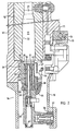
- a rotor 11 is rotatably supported in a weapon housing 10 by means of a ball bearing 13.
- six gun barrels 12 are attached by means of bayonet locks, de NEN only one gun barrel 12 is visible in FIG. 2.
- a closure 14 is assigned to each weapon barrel 12.
- Each closure 14 is slidably supported in the rotor 11 in longitudinal guides 28. These six closures 14 are shown in FIG. 1 in front view. 1, cartridges 17 are fed to the weapon 9 with the aid of an endless cup chain 15, which is wound around a star wheel 16.
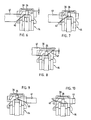
- the cartridges 17 located in the individual cups 18 of the cup chain 15 are combed out of the cup chain 15 with the aid of a star wheel 19 and moved in front of the breech 14a of the weapon 9 until the cartridge axis coincides with the weapon barrel axis (FIG. 2).
- the bottom 20 of the cartridge 17 comes to lie on the end face 21 of the closure 14.
- a pull-out claw 30 is provided on the end face 21 of the closure 14, which protrudes into an pull-out groove 25 of the cartridge case 23. So that the cartridge 17 cannot fall out of the pull-out claw 30 when inserted into the weapon barrel, a locking cam 26 is attached diagonally to the pull-out claw 30 on a stylus 27. So that the cartridge 17 can be inserted into the pull-out claw 30, the stylus 27 with the safety cam 26 must be withdrawn, as will be described further below.
- the cartridge 17 is fed in the direction of arrow Z and the empty cartridge case 23 is moved away in the direction of arrow W and this is only possible if the stylus 27 has been retracted with the cam 26 so far that the sleeve base 20 on the End face 21 of the closure 14 can slide.
- the closure 14 is composed of a closure head 31, a closure head holder 32 and a closure carrier 33.
- the closure head 31 is screwed onto the closure head holder 32 via a steep thread 34 and the closure head holder 32 is coupled via a lever 35 to the closure carrier 33 in a manner not shown.
- a roller 36 which is rotatably mounted on the breech block 33, projects into a control groove 37 of the weapon housing 10.
- the breech 14 is retracted by the control groove 37 to such an extent that the empty cartridge case 23 can be ejected and a further cartridge 17 can be fed.
- the locking head 31 rotates on the locking head holder 32 and at the same time moves from the position shown in FIG. 2 to the position shown in FIG. 3.
- the stylus 27 is guided in the locking head holder 32 and is loaded by a spring 38. This stylus 27 is held in its rearmost position by the cartridge 17 according to FIG. 2 and moves forward according to FIG. 3 when the closure head 31 is displaced, so that the locking cam 26 always has the same amount over the end face 21 of the closure 14 protrudes.
- An ignition pin 39 is slidably mounted in the closure carrier 33 and loaded by a spring 40.
- a control rail 41 is provided in order to push the stylus 27 back so far that the safety cam 26 no longer protrudes over the end face 21, so that the empty cartridge case 23 can be ejected and the next cartridge 17 can be fed.
- This control rail 41 is fastened to the weapon housing 10, as can be seen from FIG. 1.
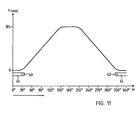
- This control curve 41 has a steeper control surface 42 at one end and a flatter control surface 43 at its other end.
- a lever 44 abuts against the control surfaces 42 and 43 and is pivotally articulated on the stylus 27 (see FIGS. 2 and 3).
- the closure 14 moves forward and remains in its foremost position when the rotation through a further 60 ° .
- the closure 14 moves back again and remains in its rearmost position when rotated through 60 °, ie from an angle of 330 ° to 30 ° .
- the stylus 27 with the locking cam 26 should be pushed back so far that the empty cartridge case 23 can be ejected and the next cartridge 17 can be fed. 1 and 11 pushes the stylus 27 with its pivotable lever 44 (FIG.
Landscapes
- Engineering & Computer Science (AREA)
- General Engineering & Computer Science (AREA)
- Portable Nailing Machines And Staplers (AREA)
- Toys (AREA)
Claims (1)
- Device for radially securing a cartridge (17) that is located behind the barrel (12) of an externally- powered multi-barrel gun, is loaded into the barrel (12) by a reciprocating breech (14), and has a cartridge case (23) with a cannelure (25), said device comprising the following:- a gun casing (10);- at least one gunbarrel (12), rotatably mounted in the gun casing (10);- a reciprocating breech (14), which cooperates with the gunbarrel (12) to load the cartridge (17) into the barrel (12);- a breech head (31) at the front end of the breech (14);- an extractor dog (30) on the breech head (31), said dog engaging with the cannelure (25) of the cartridge case (23) and preventing the cartridge (17) from slipping radially from the breech (14) in one direction;- a tracer finger (27), located diametrically opposite the extractor dog (30) and serving to ascertain whether a cartridge actually has been supplied to the barrel (12);- a guide, in which the tracer finger (27) is slidably mounted in the breech to be axially displaceable be- tween a front and a rear position;- a spring (38) which blases the tracer finger (27) and tries to hold it in its frontmost position;- said tracer finger (27) can be displaced against the force of the spring (38) into its rear position when a cartridge (17) is present, the base of which strikes the tracer finger (27),
characterised in that- the tracer finger (27) has an axially protruding safety cam (26) which laterally abuts the rim (45) of the cartridge base (20), in order to secure the cartridge against slipping out of the extractor lug (30);- a control bar (41) is fixed on the gun casing (10) and serves exclusively to push back the tracer finger (27)- when the cartridge (17) is fed in front of the barrel's breech closure.
Applications Claiming Priority (2)
| Application Number | Priority Date | Filing Date | Title |
|---|---|---|---|
| CH141786 | 1986-04-10 | ||
| CH1417/86 | 1986-04-10 |
Publications (2)
| Publication Number | Publication Date |
|---|---|
| EP0240845A1 EP0240845A1 (fr) | 1987-10-14 |
| EP0240845B1 true EP0240845B1 (fr) | 1989-04-26 |
Family
ID=4209961
Family Applications (1)
| Application Number | Title | Priority Date | Filing Date |
|---|---|---|---|
| EP87104413A Expired EP0240845B1 (fr) | 1986-04-10 | 1987-03-25 | Dispositif pour retenir radialement une cartouche pendant son chargement par la culasse dans la chambre d'un canon d'artillerie |
Country Status (3)
| Country | Link |
|---|---|
| US (1) | US4860632A (fr) |
| EP (1) | EP0240845B1 (fr) |
| DE (1) | DE3760131D1 (fr) |
Families Citing this family (5)
| Publication number | Priority date | Publication date | Assignee | Title |
|---|---|---|---|---|
| GB8728052D0 (en) * | 1987-12-01 | 1988-03-23 | Victory Arms Co Ltd | Variable calibre breech for self loading pistols |
| US5561934A (en) * | 1994-11-23 | 1996-10-08 | Modern Muzzleloading, Inc. | Breech plug and ignition system for muzzle-loading firearm |
| AR044368A1 (es) * | 2004-05-17 | 2005-09-07 | Rafael Javier Fornes | Dispositivo disparador de accion continua |
| CN104913681B (zh) * | 2015-06-18 | 2017-03-01 | 江苏科技大学 | 一种变刚度抽壳推进机构 |
| CN115930671B (zh) * | 2022-11-30 | 2025-05-06 | 西安昆仑工业(集团)有限责任公司 | 一种弹体定位装置和具有弹体定位功能的空气炮自动机 |
Family Cites Families (6)
| Publication number | Priority date | Publication date | Assignee | Title |
|---|---|---|---|---|
| GB186952A (en) * | 1921-04-16 | 1922-10-16 | William Gray | Improvements in or relating to extractor devices for machine guns |
| US1749137A (en) * | 1923-02-28 | 1930-03-04 | Automatic Guns Inc | Machine gun |
| US1783577A (en) * | 1927-07-16 | 1930-12-02 | Safat Societa Anonima Fabbrica | Device for feeding cartridges and for cocking the striker in automatic firearms |
| US3146673A (en) * | 1963-07-18 | 1964-09-01 | Frederick P Reed | Means for indexing multiprojectile cartridges into firing alignment in a multibore gun |
| US4216698A (en) * | 1978-09-25 | 1980-08-12 | General Electric Company | Balanced Gatling gun |
| US4550641A (en) * | 1982-12-08 | 1985-11-05 | Werkzeugmaschinenfabrik Oerlikon-Buhrle Ag | Safety apparatus in externally powered firing weapon |
-
1987
- 1987-03-25 EP EP87104413A patent/EP0240845B1/fr not_active Expired
- 1987-03-25 DE DE8787104413T patent/DE3760131D1/de not_active Expired
- 1987-03-30 US US07/031,861 patent/US4860632A/en not_active Expired - Fee Related
Also Published As
| Publication number | Publication date |
|---|---|
| DE3760131D1 (en) | 1989-06-01 |
| EP0240845A1 (fr) | 1987-10-14 |
| US4860632A (en) | 1989-08-29 |
Similar Documents
| Publication | Publication Date | Title |
|---|---|---|
| DE2019232C3 (de) | Verschlußeinrichtung für eine als Gasdrucklader ausgebildete Selbstladewaffe | |
| DE69220755T2 (de) | Feuerwaffe mit zwei Läufen und Zylinderverschluss | |
| DE102020113538B3 (de) | Auszieher-Vorrichtung zum momentfreien Ziehen einer Patronenhülse | |
| DE2051411C3 (de) | Verschlußeinrichtung für eine Trommelwaffe | |
| EP0111240A2 (fr) | Dispositif de sécurité pour canon à moteur externe | |
| DE3108783C2 (de) | Auszieher für Schußwaffen | |
| DE4102598C2 (de) | Automatischer Zuführmechanismus für Treibladungszünder | |
| DE1902275B2 (de) | Ladevorrichtung für automatisches Gewehr | |
| DE7332158U (de) | Gewehr | |
| DE69823926T2 (de) | Halbautomatisches Gewehr, in dem die Patronen von der Seite zugeführt werden und die Hülsen nach unten ausgeworfen werden | |
| CH627547A5 (de) | Patronenhuelsenauszieher fuer revolver. | |
| DE3871556T2 (de) | Munitionszufuehrvorrichtung fuer halbautomatische oder mittels handschieber betaetigte flinten. | |
| DE102019120184B4 (de) | Verschluss und Waffensystem mit dem Verschluss | |
| EP0240845A1 (fr) | Dispositif pour retenir radialement une cartouche pendant son chargement par la culasse dans la chambre d'un canon d'artillerie | |
| AT519342A1 (de) | Patronenhülsen-Vorwärtsauswurfsystem | |
| DE3432537C2 (de) | Repetiergewehrverschluß | |
| CH657698A5 (de) | Maschinenkanone vom gatling-typ. | |
| DE19602430C2 (de) | Verschluß für eine Schußwaffe | |
| DE2937860A1 (de) | Uebergangsschaltervorrichtung | |
| AT396299B (de) | Handfeuerwaffe, insbesondere jagdwaffe | |
| DE2057613C3 (de) | Spann- und Abzugsmechanismus für automatische Schnellfeuerwaffe | |
| EP0428525B1 (fr) | Arme a feu | |
| DE3427875C1 (de) | Automatische Feuerwaffe mit walzenfoermigem Verschlussteil | |
| DE1264294B (de) | Verschluss fuer Handfeuerwaffen | |
| DE2419185A1 (de) | Leichte rohrfeuerwaffe mit einem schwenkbaren patronenkammergehaeuse |
Legal Events
| Date | Code | Title | Description |
|---|---|---|---|
| PUAI | Public reference made under article 153(3) epc to a published international application that has entered the european phase |
Free format text: ORIGINAL CODE: 0009012 |
|
| AK | Designated contracting states |
Kind code of ref document: A1 Designated state(s): CH DE FR GB IT LI |
|
| 17P | Request for examination filed |
Effective date: 19871029 |
|
| 17Q | First examination report despatched |
Effective date: 19880623 |
|
| GRAA | (expected) grant |
Free format text: ORIGINAL CODE: 0009210 |
|
| AK | Designated contracting states |
Kind code of ref document: B1 Designated state(s): CH DE FR GB IT LI |
|
| ITF | It: translation for a ep patent filed | ||
| GBT | Gb: translation of ep patent filed (gb section 77(6)(a)/1977) | ||
| REF | Corresponds to: |
Ref document number: 3760131 Country of ref document: DE Date of ref document: 19890601 |
|
| ET | Fr: translation filed | ||
| PGFP | Annual fee paid to national office [announced via postgrant information from national office to epo] |
Ref country code: FR Payment date: 19900202 Year of fee payment: 4 |
|
| PGFP | Annual fee paid to national office [announced via postgrant information from national office to epo] |
Ref country code: CH Payment date: 19900222 Year of fee payment: 4 |
|
| PLBE | No opposition filed within time limit |
Free format text: ORIGINAL CODE: 0009261 |
|
| STAA | Information on the status of an ep patent application or granted ep patent |
Free format text: STATUS: NO OPPOSITION FILED WITHIN TIME LIMIT |
|
| PGFP | Annual fee paid to national office [announced via postgrant information from national office to epo] |
Ref country code: DE Payment date: 19900227 Year of fee payment: 4 |
|
| ITTA | It: last paid annual fee | ||
| 26N | No opposition filed | ||
| PG25 | Lapsed in a contracting state [announced via postgrant information from national office to epo] |
Ref country code: GB Effective date: 19910325 |
|
| PG25 | Lapsed in a contracting state [announced via postgrant information from national office to epo] |
Ref country code: LI Effective date: 19910331 Ref country code: CH Effective date: 19910331 |
|
| GBPC | Gb: european patent ceased through non-payment of renewal fee | ||
| PG25 | Lapsed in a contracting state [announced via postgrant information from national office to epo] |
Ref country code: FR Effective date: 19911129 |
|
| REG | Reference to a national code |
Ref country code: CH Ref legal event code: PL |
|
| PG25 | Lapsed in a contracting state [announced via postgrant information from national office to epo] |
Ref country code: DE Effective date: 19920101 |
|
| REG | Reference to a national code |
Ref country code: FR Ref legal event code: ST |
|
| PG25 | Lapsed in a contracting state [announced via postgrant information from national office to epo] |
Ref country code: IT Free format text: LAPSE BECAUSE OF NON-PAYMENT OF DUE FEES;WARNING: LAPSES OF ITALIAN PATENTS WITH EFFECTIVE DATE BEFORE 2007 MAY HAVE OCCURRED AT ANY TIME BEFORE 2007. THE CORRECT EFFECTIVE DATE MAY BE DIFFERENT FROM THE ONE RECORDED. Effective date: 20050325 |