EP0240969A2 - Appareil de remplissage de pneus, notamment pour remplir des pneus de bicyclette - Google Patents
Appareil de remplissage de pneus, notamment pour remplir des pneus de bicyclette Download PDFInfo
- Publication number
- EP0240969A2 EP0240969A2 EP19870105056 EP87105056A EP0240969A2 EP 0240969 A2 EP0240969 A2 EP 0240969A2 EP 19870105056 EP19870105056 EP 19870105056 EP 87105056 A EP87105056 A EP 87105056A EP 0240969 A2 EP0240969 A2 EP 0240969A2
- Authority
- EP
- European Patent Office
- Prior art keywords
- filling head
- tire
- cartridge
- tire inflation
- compressed gas
- Prior art date
- Legal status (The legal status is an assumption and is not a legal conclusion. Google has not performed a legal analysis and makes no representation as to the accuracy of the status listed.)
- Granted
Links
Images
Classifications
-
- B—PERFORMING OPERATIONS; TRANSPORTING
- B60—VEHICLES IN GENERAL
- B60S—SERVICING, CLEANING, REPAIRING, SUPPORTING, LIFTING, OR MANOEUVRING OF VEHICLES, NOT OTHERWISE PROVIDED FOR
- B60S5/00—Servicing, maintaining, repairing, or refitting of vehicles
- B60S5/04—Supplying air for tyre inflation
- B60S5/043—Supplying air for tyre inflation characterised by the inflation control means or the drive of the air pressure system
Definitions
- the invention relates to a tire inflator, in particular for filling bicycle tires, consisting of a F ül l - head with a connectable to the tire valve outlet opening and an inlet opening has a hollow mandrel containing a compressed gas cartridge and from a concentrically connected to the inlet port with the filling head cartridge case for Inclusion of the compressed gas cartridge.
- Tire inflators of this type can be used in place of the conventional hand air pumps and have the advantage that they are light, require little space and enable a bicycle tire to be inflated quickly and easily at a relatively high pressure. Tire inflators of this type are therefore particularly advantageous for racing cyclists.
- the invention has for its object to provide a tire inflation device of the type mentioned, which can be used to inflate different types of tires and which also allows the tires to be pumped with a small amount of gas.
- the connecting channel between the inlet opening and the outlet opening of the filling head contains an automatically closing valve which blocks the connecting channel in its closed position and which can be moved into its open position via an actuating device arranged on the filling head.
- the tire inflation device according to the invention has the advantage that, with the help of the valve, the gas volume stored in the compressed gas cartridge can be withdrawn in any quantity, so that tires of different sizes can be inflated to a freely selectable pressure up to a maximum pressure, regardless of whether the tire is empty beforehand or was already partially filled. Furthermore, higher tire pressures can also be achieved with the tire inflation device according to the invention, in that an already inflated tire is pumped with a newly inserted compressed gas cartridge which is still under higher internal pressure.
- the valve is a tire inflation valve which can be screwed into the connecting channel from the outside and which can be actuated from the outside by a plunger which closes the screw-in opening in a pressure-tight manner.
- Tire inflation valves have proven themselves in practice and are inexpensively manufactured in large quantities.
- the tire inflation device according to the invention makes use of these advantages. Furthermore, in the embodiment according to the invention, there is the advantage that the tire inflation valve can easily be unscrewed and cleaned or replaced in the event of a malfunction after the tappet has been removed.
- the inflation head consists of a cylindrical housing with a central, stepped through-bore, the central portion of which has a sealing cone and an internal thread for receiving the tire inflation valve, one end of which is expanded to accommodate the hollow mandrel and the neck of the compressed gas cartridge, and the latter other end receives the plunger for actuating the tire inflation valve.
- a reliable seal between the compressed gas cartridge and the filling head is achieved according to a further proposal of the invention in that the enlarged end of the through bore which receives the hollow mandrel contains a sealing ring in a pierced ring groove into which the neck of the compressed gas cartridge engages before piercing through the hollow mandrel.
- a transverse bore branches off from the through bore between the valve and the tappet and has a connection screw connection containing the outlet opening at its outer end.
- the tappet is actuated according to the invention by a lever which is mounted on the end face of the filling head and has a lever arm which extends on the side remote from the screw connection along the cylindrical outer surface of the filling head. This arrangement enables easy handling of the tire inflation device according to the invention with one hand.
- the lever arm can also serve as a hook for hanging the tire inflation device.
- the cartridge case has a vent hole through which its interior is connected to the atmosphere. This ensures that if the cartridge case is unscrewed before the pressure gas cartridge is completely emptied, the pressure gas can escape through the vent hole before the filling head and cartridge case are completely separated from one another. Thus, no pressure cushion can form in the cartridge case, which could explode apart when the connection between filling head and cartridge case is released.
- the cartridge case has a holder by means of which the compressed gas cartridge can be locked in the cartridge case. With the help of this holder, the compressed gas cartridge is reliably pulled out of the through hole of the filling head when the cartridge case is loosened, so that an existing residual pressure is in any case reduced via the vent hole.
- the cartridge case can be connected to the filling head in a pressure-tight manner and that a screw connection for the connection of an additional compressed air tank is formed on the base of the cartridge case, in which the vent hole opens.
- a compressed air tank of larger dimensions can be vented through the cartridge case can be connected to the tire inflation device, which can be filled at a petrol station, for example, and which can be used in the home instead of a compressed gas cartridge.
- the compressed gas container can be provided with its own filling valve, which can be pushed open by the screw connection.
- there is also the possibility of filling the compressed gas container via the tire inflation device by connecting the compressed air source to the outlet opening of the tire inflation device and at the same time actuating the valve of the tire inflation device.
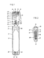
- the tire inflation device shown consists of a filling head 1 of cylindrical basic shape and a likewise cylindrical cartridge case 2, in which a bottle-shaped compressed gas cartridge 3 is located.
- the filling head 1 and the cartridge case 2 have approximately the same outside diameter.
- One end of the filling head 1 is provided with an outer thread 4 with a smaller diameter, onto which the open end of the cartridge case 2, which is provided with an inner thread 5, can be screwed.
- the filling head 1 is provided with a central through bore 8, which has a threaded section 9 and a conical sealing surface 10 in its central region. Threaded section 9 and sealing surface 10 serve to receive a tire inflation valve 11 which, as shown in FIG. 2, can be screwed into the through bore 8 from above. Above the tire inflation valve 11, the through hole 8 is closed by a displaceable tappet 12, which is sealed with a sealing ring 13 from the through hole 8.
- the plunger 12 is in operative engagement with an actuating lever 14 mounted on the end face of the filling head 1.
- the actuating lever 14 has a bent lever arm 15 which extends approximately parallel to the longitudinal axis of the filling head 1.
- the actuating lever 14 can be moved against a compression spring 16, by means of which it is held in its rest position.
- the plunger 12 can be pushed so far into the through hole 8 by actuating the actuating lever 14 that it moves the valve needle 17 of the tire inflation valve 11 against the force of the valve spring 18 and thereby lifts the valve plate 19 from the valve seat 20.
- a transverse bore 21 which leads to a threaded connection 22 into which a connecting piece or connecting hose can be screwed, through which the transverse bore 21 can be connected to the valve of a tire.
- the end of the through-bore facing the cartridge case 2 is widened in a step-like manner and contains a hollow mandrel 23 with a cylindrical base 24 which is supported on the step surface.
- the hollow mandrel 23 has a central bore 25 leading from its foot end to the tip, which in a Cross bore 26 opens.
- a sealing ring 27 is arranged in an annular groove pierced into the through bore 8, which, when the filling head 1 and cartridge case 2 are screwed into one another, encloses the neck 28 of the compressed gas cartridge 3 penetrating into the through bore 8 before the holder 23 Pressurized gas cartridge 3.
- the end of the cartridge case 2 facing away from the filling head 1 has a vent hole 29 which connects the interior of the cartridge case 2 to the atmosphere.
- the vent hole 29 is located within a depression 30 in the sleeve bottom, which is provided with an internal thread 31 and a plunger 32.
- the connection piece of a compressed air tank which is provided with an external thread, can be screwed into the depression in a pressure-tight manner, the plunger 32 keeping the filling valve of the compressed air tank open.
- the tire inflation device can thus also be supplied by a compressed air tank that can be refilled, for example, at a petrol station, the volume of which is a multiple of the compressed gas cartridge shown and which enables inexpensive stationary use of the tire inflation device.
- the drawing shows the tire inflation device in the open state, in which the compressed gas cartridge 3 can be inserted or replaced.
- the cartridge case 2 is screwed with its internal thread 5 onto the external thread 4 of the filling head 1.
- the neck 28 is pushed into the enlarged section of the through hole 8, whereby it slides over the sealing ring 27.
- the hollow mandrel 23 penetrates into the end wall of the compressed gas cartridge and penetrates it so far that the transverse bore 26 is located in the interior of the compressed gas cartridge 3 in the end position.
- the compressed gas cartridge 3 is now connected pressure-tight to the input side of the through hole 8.
- the tire inflation valve 11 is then opened by actuating the actuation lever 14, as a result of which the gas from the compressed gas cartridge 3 enters the tire via the transverse bore 26, the central bore 25, the tire inflation valve 11 and the transverse bore 21 via the tire valve.
- the operating lever 14 is now operated until the desired pressure is achieved in the tire. Since the pressure in the central part of the through bore 8 and in the transverse bore 21, which corresponds to the respective tire inflation pressure, acts on the tappet 12, the actuating force on the actuating lever 14 increases with increasing inflation pressure, so that the pressure increase in the tire can be followed in this way and doses.
- the cartridge case 2 has an easily detachable holding device arranged, through which the compressed gas cartridge 3 is fixed in the axial direction in the cartridge case 2.
- a compression spring can also be provided, which is supported on the compressed gas cartridge 3 and the filling head 1.
Landscapes
- Engineering & Computer Science (AREA)
- Mechanical Engineering (AREA)
- Vehicle Cleaning, Maintenance, Repair, Refitting, And Outriggers (AREA)
- Filling Or Discharging Of Gas Storage Vessels (AREA)
- Check Valves (AREA)
Priority Applications (1)
| Application Number | Priority Date | Filing Date | Title |
|---|---|---|---|
| AT87105056T ATE79337T1 (de) | 1986-04-09 | 1987-04-06 | Reifenfuellgeraet, insbesondere zum fuellen von fahrradreifen. |
Applications Claiming Priority (2)
| Application Number | Priority Date | Filing Date | Title |
|---|---|---|---|
| DE8609642U | 1986-04-09 | ||
| DE8609642U DE8609642U1 (de) | 1986-04-09 | 1986-04-09 | Reifenfüllgerät, insbesondere zum Füllen von Fahrradreifen |
Publications (3)
| Publication Number | Publication Date |
|---|---|
| EP0240969A2 true EP0240969A2 (fr) | 1987-10-14 |
| EP0240969A3 EP0240969A3 (en) | 1988-11-17 |
| EP0240969B1 EP0240969B1 (fr) | 1992-08-12 |
Family
ID=6793496
Family Applications (1)
| Application Number | Title | Priority Date | Filing Date |
|---|---|---|---|
| EP87105056A Expired - Lifetime EP0240969B1 (fr) | 1986-04-09 | 1987-04-06 | Appareil de remplissage de pneus, notamment pour remplir des pneus de bicyclette |
Country Status (7)
| Country | Link |
|---|---|
| US (1) | US4773454A (fr) |
| EP (1) | EP0240969B1 (fr) |
| AT (1) | ATE79337T1 (fr) |
| CA (1) | CA1302213C (fr) |
| DE (2) | DE8609642U1 (fr) |
| ES (1) | ES2033712T3 (fr) |
| GR (1) | GR3006235T3 (fr) |
Cited By (1)
| Publication number | Priority date | Publication date | Assignee | Title |
|---|---|---|---|---|
| DE4324220A1 (de) * | 1993-07-20 | 1995-01-26 | Reinhard Kurz | Reifenfüllgerät |
Families Citing this family (19)
| Publication number | Priority date | Publication date | Assignee | Title |
|---|---|---|---|---|
| US5012954A (en) * | 1990-02-08 | 1991-05-07 | Will Conrad A | Tire inflation system |
| US5121771A (en) * | 1990-02-26 | 1992-06-16 | Scott Specialty Gases | Device for depressing a tire valve core in high pressure cylinders |
| US6237251B1 (en) | 1991-08-21 | 2001-05-29 | Reebok International Ltd. | Athletic shoe construction |
| AU656022B2 (en) * | 1992-01-31 | 1995-01-19 | Reebok International Ltd. | Upper for an athletic shoe and method for manufacturing the same |
| USD336090S (en) | 1992-01-31 | 1993-06-01 | Reebok International Ltd. | Pressurized gas inflation device |
| US5407096A (en) * | 1992-11-30 | 1995-04-18 | Sherman Products Corporation | Apparatus for providing a portable source of high pressure gas |
| US5316055A (en) * | 1993-04-19 | 1994-05-31 | Brimmer John A | Bicycle tire recharge apparatus |
| USD348677S (en) | 1993-04-28 | 1994-07-12 | Reebok International Ltd. | Pressurized gas inflation device |
| US5347913A (en) * | 1993-08-23 | 1994-09-20 | Stepner David E | Portable bicycle pump having collapsible handle and footstand |
| USD358397S (en) | 1993-10-08 | 1995-05-16 | Reebok International Ltd. | Inflation device |
| US5544670A (en) * | 1993-12-15 | 1996-08-13 | Reebok International Ltd. | Inflation device for an inflatable article of manufacture and adaptor therefor |
| US5590696A (en) * | 1994-07-14 | 1997-01-07 | Reebok International Ltd. | Inflation system utilizing a pressurized gas inflation device and adaptor therefor |
| US20020194747A1 (en) | 2001-06-21 | 2002-12-26 | Passke Joel L. | Footwear with bladder filter |
| DE10206151C2 (de) * | 2002-02-14 | 2003-12-24 | Scott Wu | Schnell-Aufpumpvorrichtung für Reifen |
| US7278445B2 (en) | 2002-07-02 | 2007-10-09 | Reebok International Ltd. | Shoe having an inflatable bladder |
| US8677652B2 (en) | 2002-07-02 | 2014-03-25 | Reebok International Ltd. | Shoe having an inflatable bladder |
| US6785985B2 (en) | 2002-07-02 | 2004-09-07 | Reebok International Ltd. | Shoe having an inflatable bladder |
| US20130264360A1 (en) * | 2012-04-05 | 2013-10-10 | Brewing Tools Llc | Reusable Vessel for Dispensing Beverages and Method of Storing and Dispensing Beverages |
| WO2023039260A1 (fr) * | 2021-09-10 | 2023-03-16 | Phillips Connect Technologies Llc | Tuyau de système de gonflage de pneu automatique avec capteur tpms intégré |
Family Cites Families (10)
| Publication number | Priority date | Publication date | Assignee | Title |
|---|---|---|---|---|
| FR425636A (fr) * | 1911-01-07 | 1911-06-15 | Leon Lacour | Dispositif pour le gonflement des pneumatiques au moyen de cartouches de gaz comprimés ou liquéfiés |
| US2533685A (en) * | 1949-06-09 | 1950-12-12 | Stop Fire Inc | Fire extinguisher |
| US2876846A (en) * | 1955-11-29 | 1959-03-10 | Gen Pacific Corp | Fire extinguisher head assembly |
| GB833056A (en) * | 1957-05-22 | 1960-04-21 | Sparklets Ltd | Device for the controlled discharge of compressed fluid |
| US3632045A (en) * | 1969-05-15 | 1972-01-04 | Katsuo Oana | Portable fluid container |
| US3834433A (en) * | 1971-11-22 | 1974-09-10 | A Thompson | Cartridge-actuated device for inflating tires and the like |
| US3865158A (en) * | 1973-04-27 | 1975-02-11 | American La France Inc | Reuseable pressurized dispenser |
| AT365128B (de) * | 1979-07-06 | 1981-12-10 | Vmw Ranshofen Berndorf Ag | Gasfuelleinrichtung, insbesondere fuer aufblasbare hohlkoerper, wie fahrzeugreifen |
| DE3205264A1 (de) * | 1982-02-15 | 1983-08-25 | Löhle, Ludwig, 6120 Michelstadt | Reifenfuellgeraet fuer rennraeder oder dergleichen |
| US4658869A (en) * | 1986-05-07 | 1987-04-21 | Soon Fu Hwang | Combination tire inflator, gauge and deflator |
-
1986
- 1986-04-09 DE DE8609642U patent/DE8609642U1/de not_active Expired
-
1987
- 1987-03-30 US US07/032,328 patent/US4773454A/en not_active Expired - Fee Related
- 1987-04-03 CA CA000533834A patent/CA1302213C/fr not_active Expired - Lifetime
- 1987-04-06 EP EP87105056A patent/EP0240969B1/fr not_active Expired - Lifetime
- 1987-04-06 ES ES198787105056T patent/ES2033712T3/es not_active Expired - Lifetime
- 1987-04-06 AT AT87105056T patent/ATE79337T1/de not_active IP Right Cessation
- 1987-04-06 DE DE87105056T patent/DE3780999D1/de not_active Expired - Lifetime
-
1992
- 1992-11-12 GR GR920402573T patent/GR3006235T3/el unknown
Cited By (1)
| Publication number | Priority date | Publication date | Assignee | Title |
|---|---|---|---|---|
| DE4324220A1 (de) * | 1993-07-20 | 1995-01-26 | Reinhard Kurz | Reifenfüllgerät |
Also Published As
| Publication number | Publication date |
|---|---|
| ES2033712T3 (es) | 1993-04-01 |
| DE3780999D1 (fr) | 1992-09-17 |
| EP0240969B1 (fr) | 1992-08-12 |
| US4773454A (en) | 1988-09-27 |
| CA1302213C (fr) | 1992-06-02 |
| ATE79337T1 (de) | 1992-08-15 |
| EP0240969A3 (en) | 1988-11-17 |
| GR3006235T3 (fr) | 1993-06-21 |
| DE8609642U1 (de) | 1986-12-11 |
Similar Documents
| Publication | Publication Date | Title |
|---|---|---|
| EP0240969B1 (fr) | Appareil de remplissage de pneus, notamment pour remplir des pneus de bicyclette | |
| DE69206591T2 (de) | Kombination Sprühdose und Vorrichtung zur Herstellung eines Sprühdrucks. | |
| AT409121B (de) | Aufblasvorrichtung, insbesondere für eine rettungsweste | |
| EP0163007B1 (fr) | Soupape de distribution et de sûreté pour un siphon pour crème, ou similaire | |
| DE1132569B (de) | Ventil zum Auffuellen des Brennstoffbehaelters eines Feuerzeuges mit verfluessigtem Gas aus einem Nachfuellbehaelter | |
| DE69923922T2 (de) | Pistole zur Abgabe von gasförmigem Brennstoff | |
| DE10110713C2 (de) | Handpumpe mit automatischer und Handaufpumpfunktion | |
| DE4225997C2 (de) | Schnellöffnungsventil | |
| DE4400587A1 (de) | Vorrichtung zum Füllen und Entleeren einer Gasflasche | |
| WO2008086910A1 (fr) | Dispositif permettant d'étanchéifier et de gonfler des gonflables | |
| DE3711583A1 (de) | Reifenfuellgeraet, insbesondere zum fuellen von fahrradreifen | |
| DE3202655C1 (de) | Verfahren und Vorrichtung zum Hinzugeben einer vorgegebenen Menge einer zweiten Fluessigkeit(Dosierfluessigkeit)zu einer in einem Behaelter befindlichen ersten Fluessigkeit | |
| DE3307245C2 (de) | Verfahren zum Befüllen eines Behälters mit einem unter Druck stehenden Medium | |
| DE4120188C1 (fr) | ||
| EP0054717A1 (fr) | Dispositif pour prise de gaz | |
| DE1299184B (de) | Vorrichtung zur dosierten Abgabe von unter Druck stehenden Medien aus druckfesten Behaeltern | |
| DE3627727C1 (en) | Piercing appliance for gas bottles | |
| DE9210467U1 (de) | Reifenfüllgerät | |
| DE2931501A1 (de) | Absperrventil fuer druckgasbehaelter u.dgl., insbesondere fuer handfeuerloescher | |
| DE2448698A1 (de) | Reifen- bzw. schlauchventil | |
| DE2736281A1 (de) | Armatur fuer einen drucktank | |
| DE3515769A1 (de) | Abfuellvorrichtung fuer bier oder dergleichen fluessigkeiten | |
| DE2628825A1 (de) | Vorrichtung zum eintreiben eines stopfens in das zapfloch eines fasses | |
| DE2447648C2 (de) | Druckluftbremseinrichtung für Schienenfahrzeuge | |
| CH686527A5 (de) | Vorrichtung zum Aufpumpen von Reifen. |
Legal Events
| Date | Code | Title | Description |
|---|---|---|---|
| PUAI | Public reference made under article 153(3) epc to a published international application that has entered the european phase |
Free format text: ORIGINAL CODE: 0009012 |
|
| AK | Designated contracting states |
Kind code of ref document: A2 Designated state(s): AT BE CH DE ES FR GB GR IT LI LU NL SE |
|
| PUAL | Search report despatched |
Free format text: ORIGINAL CODE: 0009013 |
|
| AK | Designated contracting states |
Kind code of ref document: A3 Designated state(s): AT BE CH DE ES FR GB GR IT LI LU NL SE |
|
| 17P | Request for examination filed |
Effective date: 19890705 |
|
| 17Q | First examination report despatched |
Effective date: 19901017 |
|
| RAP3 | Party data changed (applicant data changed or rights of an application transferred) |
Owner name: MOSER, WILFRIED |
|
| RAP3 | Party data changed (applicant data changed or rights of an application transferred) |
Owner name: MOSER, WILFRIED |
|
| GRAA | (expected) grant |
Free format text: ORIGINAL CODE: 0009210 |
|
| AK | Designated contracting states |
Kind code of ref document: B1 Designated state(s): AT BE CH DE ES FR GB GR IT LI LU NL SE |
|
| REF | Corresponds to: |
Ref document number: 79337 Country of ref document: AT Date of ref document: 19920815 Kind code of ref document: T |
|
| REF | Corresponds to: |
Ref document number: 3780999 Country of ref document: DE Date of ref document: 19920917 |
|
| ITF | It: translation for a ep patent filed | ||
| ET | Fr: translation filed | ||
| GBT | Gb: translation of ep patent filed (gb section 77(6)(a)/1977) | ||
| REG | Reference to a national code |
Ref country code: ES Ref legal event code: FG2A Ref document number: 2033712 Country of ref document: ES Kind code of ref document: T3 |
|
| REG | Reference to a national code |
Ref country code: GR Ref legal event code: FG4A Free format text: 3006235 |
|
| PLBE | No opposition filed within time limit |
Free format text: ORIGINAL CODE: 0009261 |
|
| STAA | Information on the status of an ep patent application or granted ep patent |
Free format text: STATUS: NO OPPOSITION FILED WITHIN TIME LIMIT |
|
| 26N | No opposition filed | ||
| PGFP | Annual fee paid to national office [announced via postgrant information from national office to epo] |
Ref country code: NL Payment date: 19940430 Year of fee payment: 8 |
|
| PGFP | Annual fee paid to national office [announced via postgrant information from national office to epo] |
Ref country code: FR Payment date: 19940517 Year of fee payment: 8 |
|
| PGFP | Annual fee paid to national office [announced via postgrant information from national office to epo] |
Ref country code: GR Payment date: 19940524 Year of fee payment: 8 |
|
| PGFP | Annual fee paid to national office [announced via postgrant information from national office to epo] |
Ref country code: SE Payment date: 19940525 Year of fee payment: 8 Ref country code: AT Payment date: 19940525 Year of fee payment: 8 |
|
| PGFP | Annual fee paid to national office [announced via postgrant information from national office to epo] |
Ref country code: ES Payment date: 19940531 Year of fee payment: 8 |
|
| PGFP | Annual fee paid to national office [announced via postgrant information from national office to epo] |
Ref country code: BE Payment date: 19940607 Year of fee payment: 8 |
|
| PGFP | Annual fee paid to national office [announced via postgrant information from national office to epo] |
Ref country code: LU Payment date: 19940731 Year of fee payment: 8 |
|
| EPTA | Lu: last paid annual fee | ||
| EAL | Se: european patent in force in sweden |
Ref document number: 87105056.3 |
|
| PGFP | Annual fee paid to national office [announced via postgrant information from national office to epo] |
Ref country code: GB Payment date: 19950321 Year of fee payment: 9 |
|
| PG25 | Lapsed in a contracting state [announced via postgrant information from national office to epo] |
Ref country code: LU Free format text: LAPSE BECAUSE OF NON-PAYMENT OF DUE FEES Effective date: 19950406 Ref country code: AT Effective date: 19950406 |
|
| PG25 | Lapsed in a contracting state [announced via postgrant information from national office to epo] |
Ref country code: SE Effective date: 19950407 Ref country code: ES Free format text: LAPSE BECAUSE OF NON-PAYMENT OF DUE FEES Effective date: 19950407 |
|
| PG25 | Lapsed in a contracting state [announced via postgrant information from national office to epo] |
Ref country code: BE Effective date: 19950430 |
|
| PGFP | Annual fee paid to national office [announced via postgrant information from national office to epo] |
Ref country code: CH Payment date: 19950705 Year of fee payment: 9 |
|
| BERE | Be: lapsed |
Owner name: MOSER WILFRIED Effective date: 19950430 |
|
| PG25 | Lapsed in a contracting state [announced via postgrant information from national office to epo] |
Ref country code: GR Free format text: THE PATENT HAS BEEN ANNULLED BY A DECISION OF A NATIONAL AUTHORITY Effective date: 19951031 |
|
| PG25 | Lapsed in a contracting state [announced via postgrant information from national office to epo] |
Ref country code: NL Effective date: 19951101 |
|
| PG25 | Lapsed in a contracting state [announced via postgrant information from national office to epo] |
Ref country code: FR Effective date: 19951229 |
|
| REG | Reference to a national code |
Ref country code: GR Ref legal event code: MM2A Free format text: 3006235 |
|
| NLV4 | Nl: lapsed or anulled due to non-payment of the annual fee |
Effective date: 19951101 |
|
| EUG | Se: european patent has lapsed |
Ref document number: 87105056.3 |
|
| REG | Reference to a national code |
Ref country code: FR Ref legal event code: ST |
|
| PG25 | Lapsed in a contracting state [announced via postgrant information from national office to epo] |
Ref country code: GB Effective date: 19960406 |
|
| PG25 | Lapsed in a contracting state [announced via postgrant information from national office to epo] |
Ref country code: LI Effective date: 19960430 Ref country code: CH Effective date: 19960430 |
|
| GBPC | Gb: european patent ceased through non-payment of renewal fee |
Effective date: 19960406 |
|
| REG | Reference to a national code |
Ref country code: CH Ref legal event code: PL |
|
| REG | Reference to a national code |
Ref country code: ES Ref legal event code: FD2A Effective date: 19990405 |
|
| PG25 | Lapsed in a contracting state [announced via postgrant information from national office to epo] |
Ref country code: IT Free format text: LAPSE BECAUSE OF NON-PAYMENT OF DUE FEES;WARNING: LAPSES OF ITALIAN PATENTS WITH EFFECTIVE DATE BEFORE 2007 MAY HAVE OCCURRED AT ANY TIME BEFORE 2007. THE CORRECT EFFECTIVE DATE MAY BE DIFFERENT FROM THE ONE RECORDED. Effective date: 20050406 |
|
| PGFP | Annual fee paid to national office [announced via postgrant information from national office to epo] |
Ref country code: DE Payment date: 20060630 Year of fee payment: 20 |