EP0241015A2 - Light fixture - Google Patents
Light fixture Download PDFInfo
- Publication number
- EP0241015A2 EP0241015A2 EP87105210A EP87105210A EP0241015A2 EP 0241015 A2 EP0241015 A2 EP 0241015A2 EP 87105210 A EP87105210 A EP 87105210A EP 87105210 A EP87105210 A EP 87105210A EP 0241015 A2 EP0241015 A2 EP 0241015A2
- Authority
- EP
- European Patent Office
- Prior art keywords
- housing
- lamp
- luminaire
- housing parts
- conductor rails
- Prior art date
- Legal status (The legal status is an assumption and is not a legal conclusion. Google has not performed a legal analysis and makes no representation as to the accuracy of the status listed.)
- Withdrawn
Links
Images
Classifications
-
- F—MECHANICAL ENGINEERING; LIGHTING; HEATING; WEAPONS; BLASTING
- F21—LIGHTING
- F21V—FUNCTIONAL FEATURES OR DETAILS OF LIGHTING DEVICES OR SYSTEMS THEREOF; STRUCTURAL COMBINATIONS OF LIGHTING DEVICES WITH OTHER ARTICLES, NOT OTHERWISE PROVIDED FOR
- F21V21/00—Supporting, suspending, or attaching arrangements for lighting devices; Hand grips
- F21V21/14—Adjustable mountings
- F21V21/30—Pivoted housings or frames
-
- F—MECHANICAL ENGINEERING; LIGHTING; HEATING; WEAPONS; BLASTING
- F21—LIGHTING
- F21S—NON-PORTABLE LIGHTING DEVICES; SYSTEMS THEREOF; VEHICLE LIGHTING DEVICES SPECIALLY ADAPTED FOR VEHICLE EXTERIORS
- F21S8/00—Lighting devices intended for fixed installation
Definitions
- the invention relates to a lamp with a substantially hemispherical, lamp-receiving housing which is pivotally connected to a support arm extending from a lamp frame.
- luminaire frame is intended to encompass all types of constructions, such as those found in floor lamps, table lamps, ceiling lamps, wall lamps, etc.
- it is customary to pivotally and / or rotatably connect the actual lamp housing to a support arm, so that the direction of exit of the light can be freely selected.
- a joint is provided in a suitable position at the transition between the support arm and the lamp housing, which, in the case of a concealed cable guide, has to accommodate the power supply cables for the lamp.
- the power supply cables are therefore quickly destroyed if the lamp housing is adjusted frequently. It is therefore sometimes also customary to route the cables freely past the joint. However, this is often undesirable for optical reasons.
- the invention is therefore based on the object of providing a luminaire of the type mentioned at the beginning, the lamp housing of which can be adjusted easily and over an almost arbitrarily large angular range, without the risk of destruction of the power supply conductors with frequent adjustment.
- the power is not supplied via cables that have to be bent back and forth with each adjustment process, but with the aid of conductor rails. If the housing has the shape of a hemisphere, the support arm connected to the slide piece can be directed to the center of the circle of the housing in any position. The pivoting therefore does not take place around a point lying outside the housing, but rather around the optical center of the housing itself. This leads to a stable and also optically satisfactory support of the housing in each of its positions.
- the housing is preferably divided in the line determined by the conductor rails and thus consists of two housing parts that can be detachably connected.
- the division makes the manufacture and assembly of the lamp much easier.
- the connected housing parts form a groove on the outside, in the side walls of which there are white slots which serve to receive the conductor rails and the pantograph fingers of the slider sliding thereon.
- the housing parts can be connected and locked in the manner of a bayonet lock.
- an insert ring is preferably inserted, the portion of which enters the housing is frustoconical and directly adjoins a reflector fastened within the housing.
- a reflector fastened within the housing.
- an outwardly projecting flange which serves as a closure for the housing.
- a cylindrical extension can be inserted into the housing if an elongated housing shape is desired in the axial direction.
- the two housing parts can also be separated and connected by a semi-cylindrical intermediate piece so that an elongated bowl is created.
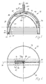
- a housing 10 for a lamp shown in FIG. 1 has the shape of a hemisphere with a relatively short cylindrical extension on the open side.
- the housing 10 consists of two mirror-image and interlocked housing parts 12, 14, the division line of which is designated by 16. Along this dividing line 16, a groove 18 runs over the housing surface, in which a slide 20 can be slid, which is connected to a lamp frame, not shown, via a support arm, not shown.
- An insert ring 22 is inserted into the open end of the housing 10, the portion 24 lying inside the housing is conical and has a stepped profile on the inner surface.
- a reflector 26 directly adjoins the inner end of section 24 and is held in the housing in a manner not shown.
- a socket 28 for a lamp for example for a halogen lamp volt lamp.
- a lamp for example for a halogen lamp volt lamp.
- an outwardly projecting flange 30 which serves as a closure for the edge of the housing.
- the two housing parts 12, 14 are connected to one another in the manner of a bayonet catch.
- they have on the mutually facing edges in a complementary arrangement in each case on one side an inwardly directed web 32 with concentric slots 34, 36 and on the other side projecting hooks 38, 40 in the direction of the respectively adjacent housing part, of which in Fig. 1 hatched the base part and the projecting hook part is shown in dashed lines.
- the hooks 38, 40 enter the slots 34, 36 of the respective other housing part and, after a slight mutual rotation, engage behind the webs 32.
- a projection directed towards the other housing part is provided on the housing parts, which strikes against a shoulder on the respective other housing part during said rotary movement.
- the projection and shoulder have aligned holes so that they can be connected by screws.
- the insert ring 22 is also inserted into the assembled housing parts 12, 14 in the manner of a bayonet connection.
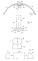
- the slider 20 consists of an arcuate section 62 entering the groove 20 and a section 64 angled perpendicularly therefrom and radially emerging from the groove, which serves for connection to a support arm, not shown.
- FIG. 4 shows an enlarged view from the right in FIG. 1. The entire slider is divided in the vertical direction in Fig. 4 into two mirror-image halves, so that lead wires can be inserted into the interior without difficulty. The cohesion is achieved by positive interaction with the groove 18 and the slots 46, 48.
- the cross section of the section 62 which slides in the groove 18 corresponds to two letters F which are placed against one another with the back.
- the upper cross line corresponds to projecting flanges 66, 68 which overlap the edges of the housing parts 12, 14 adjacent to the groove 18 from the outside.
- the middle cross lines are the pantograph fingers 50, 52 which enter the slots 46, 48.
- the flanges 66, 68 and the pantograph fingers 50, 52 run in an arc shape corresponding to the bend in the groove 18.
- the on conductor tracks 78.80 slide at the bottom of the slots 46.48.
- the current collector wires 74, 76 are connected to lead wires 82, 84 which are led out separately from one another in the section 64 of the slider.
- Fig. 2 it can be seen that the conductor tracks 78, 80 are not led to the left end of the slots in Fig. 2, but break off prematurely. This is based on the fact that the slider 20 can only be moved to the left in FIG. 1 up to a stop 86. To achieve all conceivable setting directions of the housing axis, it is sufficient if the sliding piece 20 can be displaced by 90 ° between the axial position shown in FIG. 1 and a radial position lying to the right in FIG. 1, provided that a rotation possibility is additionally provided.
- FIG. 5 and 6 schematically illustrate the use of the housing parts 12, 14 in connection with a modular system for producing different housing shapes.
- the housing parts 12, 14 are connected to one another in the manner described, and a cylindrical extension 88 is fastened instead of the insert ring 22.
- a semi-cylindrical intermediate piece 90 is placed between the two housing parts 12, 14 and has, at its two front ends, complementary connecting members for connection to the housing parts, not shown.
Landscapes
- Engineering & Computer Science (AREA)
- General Engineering & Computer Science (AREA)
- Fastening Of Light Sources Or Lamp Holders (AREA)
Abstract
Description
Die Erfindung betrifft eine Leuchte mit einem im wesentlichen halbkugelförmigen, eine Lampe aufnehmenden Gehäuse, das schwenkbar mit einem von einem Leuchtengestell ausgehenden Tragarm verbunden ist.The invention relates to a lamp with a substantially hemispherical, lamp-receiving housing which is pivotally connected to a support arm extending from a lamp frame.
Derartige Leuchten sind in zahlreichen Ausführungsformen bekannt. Mit dem Begriff des Leuchtengestells sollen hier gleichermaßen Konstruktionen aller Art umfaßt werden, wie sie bei Stehleuchten, Tischleuchten, Deckenleuchten, Wandleuchten etc. auftreten. Bei zahlreichen Leuchten ist es üblich, das eigentliche Lampengehäuse schwenkbar und/oder drehbar mit einem Tragarm zu verbinden, so daß die Austrittsrichtung des Lichtes frei wählbar ist. Zur schwenkbaren Verstellung ist in einer geeigneten Position am Übergang zwischen Tragarm und Lampengehäuse ein Gelenk vorgesehen, das im Falle einer verdeckten Kabelführung die Stromversorgungskabel für die Lampe aufnehmen muß. Die Stromversorgungskabel werden daher bei häufiger Verstellung des Lampengehäuses rasch zerstört. Es ist daher teilweise auch üblich, die Kabel frei an dem Gelenk vorbeizuführen. Dies ist jedoch aus optischen Gründen oft unerwünscht.Such lights are known in numerous embodiments. The term luminaire frame is intended to encompass all types of constructions, such as those found in floor lamps, table lamps, ceiling lamps, wall lamps, etc. In the case of numerous luminaires, it is customary to pivotally and / or rotatably connect the actual lamp housing to a support arm, so that the direction of exit of the light can be freely selected. For pivotable adjustment, a joint is provided in a suitable position at the transition between the support arm and the lamp housing, which, in the case of a concealed cable guide, has to accommodate the power supply cables for the lamp. The power supply cables are therefore quickly destroyed if the lamp housing is adjusted frequently. It is therefore sometimes also customary to route the cables freely past the joint. However, this is often undesirable for optical reasons.
Der Erfindung liegt daher die Aufgabe zugrunde, eine Leuchte der eingangs genannten Art zu schaffen, deren Lampengehäuse leicht und über einen nahezu beliebig großen Winkelbereich verstellbar ist, ohne daß bei häufiger Verstellung die Gefahr einer Zerstörung der Stromzufuhrleiter besteht.The invention is therefore based on the object of providing a luminaire of the type mentioned at the beginning, the lamp housing of which can be adjusted easily and over an almost arbitrarily large angular range, without the risk of destruction of the power supply conductors with frequent adjustment.
Diese Aufgabe wird erfindungsgemäß bei einer Leuchte der obigen Art dadurch gelöst, daß in die Außenfläche des Gehäuses Leiterschienen nach Art einer Stromschiene eingebettet sind, die elektrisch mit der Lampe in Verbindung stehen und in denen ein mit elektrischen Kontakten versehenes und mit dem Tragarm verbundenes Gleitstück gleitend verschiebbar ist.This object is achieved in a luminaire of the above type in that in the outer surface of the housing conductor rails are embedded in the manner of a busbar, which are electrically connected to the lamp and in which a slide provided with electrical contacts and connected to the support arm slidably is movable.
Die Stromzufuhr erfolgt also nicht über Kabel, die bei jedem Verstellvorgang hin- und hergebogen werden müssen, sondern mit Hilfe von Leiterschienen. Sofern das Gehäuse die Form einer Halbkugel aufweist, kann der mit dem Gleitstück verbundene Tragarm in jeder Stellung zum Kreismittelpunkt des Gehäuses gerichtet sein. Die Schwenkung erfolgt also nicht um einen außerhalb des Gehäuses liegenden Punkt, sondern um den optischen Mittelpunkt des Gehäuses selbst. Dies führt zu einer stabilen und auch optisch befriedigenden Abstützung des Gehäuses in jeder seiner Positionen.The power is not supplied via cables that have to be bent back and forth with each adjustment process, but with the aid of conductor rails. If the housing has the shape of a hemisphere, the support arm connected to the slide piece can be directed to the center of the circle of the housing in any position. The pivoting therefore does not take place around a point lying outside the housing, but rather around the optical center of the housing itself. This leads to a stable and also optically satisfactory support of the housing in each of its positions.
Das Gehäuse ist vorzugsweise in der durch die Leiterschienen bestimmten Linie geteilt und besteht somit aus zwei lösbar zu verbindenden Gehäuseteilen. Durch die Teilung werden Herstellung und Montage der Leuchte wesentlich erleichtert. Die verbundenen Gehäuseteile bilden auf der Außenseite eine Nut, in deren seitlichen Wänden sich weiSchlitze befinden, die zur Aufnahme der Leiterschienen und der auf diesen gleitenden Stromabnehmerfinger des Gleitstücks dienen. Die Gehäuseteile können nach Art eines Bajonettverschlusses miteinander verbunden und verrastet werden.The housing is preferably divided in the line determined by the conductor rails and thus consists of two housing parts that can be detachably connected. The division makes the manufacture and assembly of the lamp much easier. The connected housing parts form a groove on the outside, in the side walls of which there are white slots which serve to receive the conductor rails and the pantograph fingers of the slider sliding thereon. The housing parts can be connected and locked in the manner of a bayonet lock.
In die offene Seite des Gehäuses ist vorzugsweise ein Einsatzring eingesetzt, dessen in das Gehäuse eintretender Abschnitt kegelstumpfförmig ausgebildet ist und unmittelbar an einen innerhalb des Gehäuses befestigten Reflektor anschließt. Am äußeren Ende befindet sich ein nach außen vorspringender Flansch, der als Abschluß für das Gehäuse dient.In the open side of the housing, an insert ring is preferably inserted, the portion of which enters the housing is frustoconical and directly adjoins a reflector fastened within the housing. At the outer end is an outwardly projecting flange, which serves as a closure for the housing.
Anstelle des Einsatzringes kann eine zylindrische Verlängerung in das Gehäuse eingesetzt werden, sofern eine in Axialrichtung langgestreckte Gehäuseform erwünscht ist. Andererseits können die beiden Gehäuseteile auch getrennt und durch ein halbzylindrisches Zwischenstück verbunden werden, so daß eine langgestreckte Schale entsteht.Instead of the insert ring, a cylindrical extension can be inserted into the housing if an elongated housing shape is desired in the axial direction. On the other hand, the two housing parts can also be separated and connected by a semi-cylindrical intermediate piece so that an elongated bowl is created.
Im folgenden werden bevorzugte Ausführungsbeispiele der Erfindung anhand der beigefügten Zeichnung näher erläutert.
- Fig. 1 ist ein senkrechter Schnitt durch ein Lampengehäuse einer erfindungsgemäßen Leuchte;
- Fig. 2 ist eine zugehörige Draufsicht;
- Fig. 3 ist ein senkrechter Teilschnitt in einer zu Fig. 1 senkrechten Ebene;
- Fig. 4 ist eine Ansicht eines Gleitstücks;
- Fig. 5 und 6 veranschaulichen Ergänzungsmöglichkeiten für das Gehäuse.
- Fig. 1 is a vertical section through a lamp housing of a lamp according to the invention;
- Fig. 2 is an associated plan view;
- Fig. 3 is a partial vertical section in a plane perpendicular to Fig. 1;
- Fig. 4 is a view of a slider;
- 5 and 6 illustrate possible additions for the housing.
Ein in Fig. 1 gezeigtes Gehäuse 10 für eine Lampe weist die Form einer Halbkugel mit einer verhältnismäßig kurzen zylindrischen Verlängerung an der offenen Seite auf. Das Gehäuse 10 besteht aus zwei spiegelbildlichen und miteinander verrasteten Gehäuseteilen 12,14, deren Teilungslinie mit 16 bezeichnet ist. Entlang dieser Teilungslinie 16 verläuft über die Gehäuseoberfläche eine Nut 18, in der ein Gleitstück 20 gleitend verschiebbar ist, das über einen nicht gezeigten Tragarm mit einem nicht gezeigten Leuchtengestell verbunden ist. In das offene Ende des Gehäuses 10 ist ein Einsatzring 22 eingefügt, dessen innerhalb des Gehäuses liegender Abschnitt 24 kegelförmig ausgebildet ist und auf der Innenfläche eine stufige Profilierung aufweist. In das innere Ende des Abschnittes 24 schließt ein Reflektor 26 unmittelbar an, der in nicht gezeigter Weise in dem Gehäuse gehalten ist. Im Scheitelpunkt des Reflektors befindet sich eine Fassung 28 für eine Lampe, beispielsweise für eine Halogen-Nieder voltlampe. Am äußeren Ende des Abschnitts 24 des Einsatzringes 22 befindet sich ein nach außen vorspringender Flansch 30, der als Abschluß für den Rand des Gehäuses dient.A
Die beiden Gehäuseteile 12,14 sind nach Art eines Bajonettverschlusses miteinander verbunden. Zu diesem Zweck weisen sie an den einander zugewandten Rändern in komplementärer Anordnung jeweils auf einer Seite einen nach innen gerichteten Steg 32 mit konzentrischen Schlitzen 34,36 und auf der anderen Seite in Richtung des jeweils angrenzenden Gehäuseteils vorspringende Haken 38,40 auf, von denen in Fig. 1 das Basisteil schraffiert und das vorspringende Hakenteil gestrichelt dargestellt ist. Die Haken 38,40 treten beim Zusammensetzen der beiden Gehäuseteile in die Schlitze 34,36 des jeweils anderen Gehäuseteils ein und greifen nach geringfügiger gegenseitiger Verdrehung hinter die Stege 32. Im übrigen ist an den Gehäuseteilen jeweils ein in Richtung des anderen Gehäuseteils gerichteter Vorsprung vorgesehen, der bei der genannten Drehbewegung gegen einen Ansatz am jeweils anderen Gehäuseteil anschlägt. Vorsprung und Ansatz weisen fluchtende Bohrungen auf, so daß sie durch Schrauben verbunden werden können.The two
Das Einsetzen des Einsatzringes 22 in die zusammengefügten Gehäuseteile 12,14 erfolgt ebenfalls nach Art einer Bajonettverbindung. An der Außenseite des Abschnitts 24 des Einsatzringes 22 befinden sich kurze Rippen 42, die nach dem Einsetzen und geringfügigen Verdrehen des Einsatzringes hinter entsprechende Rippen 44 an der Innenseite der Gehäuseteile greifen.The
In den beiden Seitenwänden der Nut 18, die in der Trennfuge der Gehäuseteile gebildet wird, befinden sich durchgehende Nuten oder Schlitze 46,48, die zur Aufnahme von nicht gezeigten Leiterbahnen und zugleich als Gleitfüh rung für Stromabnehmerfinger 50,52 des Gleitstücks 20 dienen (Fig. 3 und 4). Das Material der im übrigen schalenförmigen Gehäuseteile 12,14 weist im Bereich der Ränder eine Verstärkung 54,56 auf, die die Unterbringung der Schlitze 46,48 und die Bildung einer ausreichend tiefen Nut 18 gestattet. Eine ausreichend große Dimensionierung der Nut 18 ist erforderlich zur entsprechenden Dimensionierung des Gleitstücks, das das Gehäuse tragen muß. Der Boden der Nut 18 wird verschlossen durch zwei von den beiden Gehäuseteilen ausgehenden Lippen 58,60. Im Bereich der freien Kanten der Lippen 58,60 und bündig mit diesen sind komplementär versetzt die beiden Stege 32 angeordnet. Die Haken 38,40 befinden sich jeweils unterhalb der den Stegen gegenüberliegenden Lippen.In the two side walls of the
Das Gleitstück 20 besteht aus einem bogenförmigen, in die Nut 20 eintretenden Abschnitt 62 und einem senkrecht von diesem abgewinkelten, radial aus der Nut austretenden Abschnitt 64, der zur Verbindung mit einem nicht gezeigten Tragarm dient. In Fig. 4 ist eine vergrößerte Ansicht von rechts in Fig. 1 gezeigt. Das gesamte Gleitstück ist in senkrechter Richtung in Fig. 4 in zwei spiegelbildliche Hälften geteilt, so daß in das Innere ohne Schwierigkeiten Leitungsdrähte eingelegt werden können. Der Zusammenhalt erfolgt durch formschlüssiges Zusammenwirken mit der Nut 18 und den Schlitzen 46,48. Der Querschnitt des Abschnitts 62, der in der Nut 18 gleitet, entspricht zwei mit dem Rücken gegeneinander gelegten Buchstaben F. Der obere Querstrich entspricht vorspringenden Flanschen 66,68, die die Ränder der Gehäuseteile 12,14 angrenzend an die Nut 18 von außen übergreifen. Die mittleren Querstriche sind die Stromabnehmerfinger 50,52, die in die Schlitze 46,48 eintreten. Die Flansche 66,68 und die Stromabnehmerfinger 50,52 verlaufen bogenförmig entsprechend der Biegung der Nut 18. An der Unterseite der Stromabnehmerfinger 50,52 befinden sich Taschen 70,72, in die federnde Stromabnehmerdrähte 74,76 eingelegt sind (Fig. 2), die auf Leiterbahnen 78,80 am Grunde der Schlitze 46,48 gleiten. Die Stromabnehmerdrähte 74,76 sind mit Leitungsdrähten 82,84 verbunden, die getrennt voneinander in dem Abschnitt 64 des Gleitstücks herausgeführt werden.The
In Fig. 2 ist erkennbar, daß die Leiterbahnen 78,80 nicht bis zum linken Ende der Schlitze in Fig. 2 geführt sind, sondern vorzeitig abbrechen. Dies beruht darauf, daß das Gleitstück 20 nur bis zu einem Anschlag 86 nach links in Fig. 1 verschiebbar ist. Zur Erzielung aller denkbaren Einstellrichtungen der Gehäuseachse reicht es aus, wenn das Gleitstück 20 zwischen der in Fig. 1 gezeigten, axialen Stellung und einer nach rechts in Fig. 1 liegenden, radialen Stellung um 90° verschiebbar ist, sofern zusätzlich eine Drehmöglichkeit vorgesehen ist.In Fig. 2 it can be seen that the conductor tracks 78, 80 are not led to the left end of the slots in Fig. 2, but break off prematurely. This is based on the fact that the
Fig. 5 und 6 veranschaulichen schematisch die Verwendung der Gehäuseteile 12,14 im Zusammenhang mit einem Baukastensystem zur Herstellung unterschiedlicher Gehäuseformen. Gemäß Fig. 5 sind die Gehäuseteile 12,14 in der beschriebenen Weise miteinander verbunden, und anstelle des Einsatzringes 22 ist eine zylindrische Verlängerung 88 befestigt. Gemäß Fig. 6 ist zwischen die beiden Gehäuseteile 12,14 ein halbzylindrisches Zwischenstück 90 gesetzt, das an seinen beiden stirnseitigen Enden in nicht gezeigter Weise komplementäre Verbindungsorgane zur Verbindung mit den Gehäuseteilen aufweist.5 and 6 schematically illustrate the use of the
Claims (11)
Applications Claiming Priority (2)
| Application Number | Priority Date | Filing Date | Title |
|---|---|---|---|
| DE3611826 | 1986-04-08 | ||
| DE3611826 | 1986-04-08 |
Publications (2)
| Publication Number | Publication Date |
|---|---|
| EP0241015A2 true EP0241015A2 (en) | 1987-10-14 |
| EP0241015A3 EP0241015A3 (en) | 1989-06-14 |
Family
ID=6298244
Family Applications (1)
| Application Number | Title | Priority Date | Filing Date |
|---|---|---|---|
| EP87105210A Withdrawn EP0241015A3 (en) | 1986-04-08 | 1987-04-01 | Light fixture |
Country Status (1)
| Country | Link |
|---|---|
| EP (1) | EP0241015A3 (en) |
Cited By (2)
| Publication number | Priority date | Publication date | Assignee | Title |
|---|---|---|---|---|
| GB2416200A (en) * | 2004-06-02 | 2006-01-18 | Bespoke Lighting Ltd | Picture Light Having Movable Light Modules |
| CN100465504C (en) * | 2004-12-30 | 2009-03-04 | 财团法人工业技术研究院 | Light source reflection type lighting device |
Family Cites Families (6)
| Publication number | Priority date | Publication date | Assignee | Title |
|---|---|---|---|---|
| GB261527A (en) * | 1925-10-17 | 1926-11-25 | Ceag Miners Supply Company Ltd | Improvements in safety electric hand lamps |
| US2226252A (en) * | 1939-11-16 | 1940-12-24 | Century Lighting Inc | Lighting fixture construction |
| CH268315A (en) * | 1941-02-08 | 1950-05-15 | Hyman Henry | Portable electric lamp. |
| US2499250A (en) * | 1948-05-26 | 1950-02-28 | Kasher Sam | Electric lighting fixture |
| FR1361058A (en) * | 1963-06-24 | 1964-05-15 | Adjustable light beam wall lamp | |
| GB1588657A (en) * | 1978-04-28 | 1981-04-29 | Rotaflex Ltd | Lamp holder |
-
1987
- 1987-04-01 EP EP87105210A patent/EP0241015A3/en not_active Withdrawn
Cited By (2)
| Publication number | Priority date | Publication date | Assignee | Title |
|---|---|---|---|---|
| GB2416200A (en) * | 2004-06-02 | 2006-01-18 | Bespoke Lighting Ltd | Picture Light Having Movable Light Modules |
| CN100465504C (en) * | 2004-12-30 | 2009-03-04 | 财团法人工业技术研究院 | Light source reflection type lighting device |
Also Published As
| Publication number | Publication date |
|---|---|
| EP0241015A3 (en) | 1989-06-14 |
Similar Documents
| Publication | Publication Date | Title |
|---|---|---|
| EP2026425B1 (en) | Electricity rail system | |
| EP1293724A1 (en) | Lighting channel system | |
| DE10025648A1 (en) | Track system | |
| AT517530A2 (en) | Profile lamp assembly, connecting element for such a profile lamp assembly and method for producing such a profile lamp assembly | |
| DE10025647A1 (en) | Current rail system for lamps has bearer rail containing current conducting profile consisting of at least two wire holding elements joined together with grooves for accommodating wires | |
| AT526098B1 (en) | Fastening device for fastening a lighting assembly and lighting arrangement with at least one such fastening device | |
| EP0739618B1 (en) | Supply unit for sickrooms | |
| DE19511839A1 (en) | Electric scissor lattice lamp | |
| EP0285627B1 (en) | Lighting system with lamps arranged between two low-voltage conductors | |
| EP0241015A2 (en) | Light fixture | |
| EP3876364B1 (en) | Rail illumination system | |
| EP1473807A1 (en) | Busbars system for illumination and locking device | |
| DE10139336B4 (en) | Modular lighting system | |
| DE20315234U1 (en) | Lighting device especially a table lamp, has many light sources in a housing and a mechanical and electrical connection which can be freely rotated about the holder | |
| DE4032622C2 (en) | ||
| DE4432302C2 (en) | Lamp fastening device that can be inserted into a luminaire housing | |
| DE3590122T1 (en) | Hanging decoration lighting device | |
| DE2016334A1 (en) | Coupling bodies, in particular for frameworks for display and storage purposes | |
| DE202018106946U1 (en) | Luminaire, in particular wall, ceiling or pendant luminaire | |
| EP0340532A2 (en) | Low-voltage lamp | |
| EP0151674A2 (en) | Domestic and/or work lamp | |
| DE20021009U1 (en) | High-voltage light rail system | |
| DE3937026A1 (en) | Lighting system for TV film or stage - has two longitudinal traverses arranged parallel to roof, cross traverses and guide carriage | |
| EP0256439B1 (en) | Attachment for at least one lamp | |
| EP0193014B1 (en) | Wall-mounted bed light fixture |
Legal Events
| Date | Code | Title | Description |
|---|---|---|---|
| PUAI | Public reference made under article 153(3) epc to a published international application that has entered the european phase |
Free format text: ORIGINAL CODE: 0009012 |
|
| AK | Designated contracting states |
Kind code of ref document: A2 Designated state(s): AT BE CH DE ES FR GB GR IT LI LU NL SE |
|
| RBV | Designated contracting states (corrected) |
Designated state(s): AT DE GB NL SE |
|
| PUAL | Search report despatched |
Free format text: ORIGINAL CODE: 0009013 |
|
| AK | Designated contracting states |
Kind code of ref document: A3 Designated state(s): AT DE GB NL SE |
|
| STAA | Information on the status of an ep patent application or granted ep patent |
Free format text: STATUS: THE APPLICATION IS DEEMED TO BE WITHDRAWN |
|
| 18D | Application deemed to be withdrawn |
Effective date: 19891215 |