EP0241015A2 - Lampe - Google Patents
Lampe Download PDFInfo
- Publication number
- EP0241015A2 EP0241015A2 EP87105210A EP87105210A EP0241015A2 EP 0241015 A2 EP0241015 A2 EP 0241015A2 EP 87105210 A EP87105210 A EP 87105210A EP 87105210 A EP87105210 A EP 87105210A EP 0241015 A2 EP0241015 A2 EP 0241015A2
- Authority
- EP
- European Patent Office
- Prior art keywords
- housing
- lamp
- luminaire
- housing parts
- conductor rails
- Prior art date
- Legal status (The legal status is an assumption and is not a legal conclusion. Google has not performed a legal analysis and makes no representation as to the accuracy of the status listed.)
- Withdrawn
Links
Images
Classifications
-
- F—MECHANICAL ENGINEERING; LIGHTING; HEATING; WEAPONS; BLASTING
- F21—LIGHTING
- F21V—FUNCTIONAL FEATURES OR DETAILS OF LIGHTING DEVICES OR SYSTEMS THEREOF; STRUCTURAL COMBINATIONS OF LIGHTING DEVICES WITH OTHER ARTICLES, NOT OTHERWISE PROVIDED FOR
- F21V21/00—Supporting, suspending, or attaching arrangements for lighting devices; Hand grips
- F21V21/14—Adjustable mountings
- F21V21/30—Pivoted housings or frames
-
- F—MECHANICAL ENGINEERING; LIGHTING; HEATING; WEAPONS; BLASTING
- F21—LIGHTING
- F21S—NON-PORTABLE LIGHTING DEVICES; SYSTEMS THEREOF; VEHICLE LIGHTING DEVICES SPECIALLY ADAPTED FOR VEHICLE EXTERIORS
- F21S8/00—Lighting devices intended for fixed installation
Definitions
- the invention relates to a lamp with a substantially hemispherical, lamp-receiving housing which is pivotally connected to a support arm extending from a lamp frame.
- luminaire frame is intended to encompass all types of constructions, such as those found in floor lamps, table lamps, ceiling lamps, wall lamps, etc.
- it is customary to pivotally and / or rotatably connect the actual lamp housing to a support arm, so that the direction of exit of the light can be freely selected.
- a joint is provided in a suitable position at the transition between the support arm and the lamp housing, which, in the case of a concealed cable guide, has to accommodate the power supply cables for the lamp.
- the power supply cables are therefore quickly destroyed if the lamp housing is adjusted frequently. It is therefore sometimes also customary to route the cables freely past the joint. However, this is often undesirable for optical reasons.
- the invention is therefore based on the object of providing a luminaire of the type mentioned at the beginning, the lamp housing of which can be adjusted easily and over an almost arbitrarily large angular range, without the risk of destruction of the power supply conductors with frequent adjustment.
- the power is not supplied via cables that have to be bent back and forth with each adjustment process, but with the aid of conductor rails. If the housing has the shape of a hemisphere, the support arm connected to the slide piece can be directed to the center of the circle of the housing in any position. The pivoting therefore does not take place around a point lying outside the housing, but rather around the optical center of the housing itself. This leads to a stable and also optically satisfactory support of the housing in each of its positions.
- the housing is preferably divided in the line determined by the conductor rails and thus consists of two housing parts that can be detachably connected.
- the division makes the manufacture and assembly of the lamp much easier.
- the connected housing parts form a groove on the outside, in the side walls of which there are white slots which serve to receive the conductor rails and the pantograph fingers of the slider sliding thereon.
- the housing parts can be connected and locked in the manner of a bayonet lock.
- an insert ring is preferably inserted, the portion of which enters the housing is frustoconical and directly adjoins a reflector fastened within the housing.
- a reflector fastened within the housing.
- an outwardly projecting flange which serves as a closure for the housing.
- a cylindrical extension can be inserted into the housing if an elongated housing shape is desired in the axial direction.
- the two housing parts can also be separated and connected by a semi-cylindrical intermediate piece so that an elongated bowl is created.
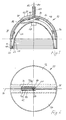
- a housing 10 for a lamp shown in FIG. 1 has the shape of a hemisphere with a relatively short cylindrical extension on the open side.
- the housing 10 consists of two mirror-image and interlocked housing parts 12, 14, the division line of which is designated by 16. Along this dividing line 16, a groove 18 runs over the housing surface, in which a slide 20 can be slid, which is connected to a lamp frame, not shown, via a support arm, not shown.
- An insert ring 22 is inserted into the open end of the housing 10, the portion 24 lying inside the housing is conical and has a stepped profile on the inner surface.
- a reflector 26 directly adjoins the inner end of section 24 and is held in the housing in a manner not shown.
- a socket 28 for a lamp for example for a halogen lamp volt lamp.
- a lamp for example for a halogen lamp volt lamp.
- an outwardly projecting flange 30 which serves as a closure for the edge of the housing.
- the two housing parts 12, 14 are connected to one another in the manner of a bayonet catch.
- they have on the mutually facing edges in a complementary arrangement in each case on one side an inwardly directed web 32 with concentric slots 34, 36 and on the other side projecting hooks 38, 40 in the direction of the respectively adjacent housing part, of which in Fig. 1 hatched the base part and the projecting hook part is shown in dashed lines.
- the hooks 38, 40 enter the slots 34, 36 of the respective other housing part and, after a slight mutual rotation, engage behind the webs 32.
- a projection directed towards the other housing part is provided on the housing parts, which strikes against a shoulder on the respective other housing part during said rotary movement.
- the projection and shoulder have aligned holes so that they can be connected by screws.
- the insert ring 22 is also inserted into the assembled housing parts 12, 14 in the manner of a bayonet connection.
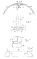
- the slider 20 consists of an arcuate section 62 entering the groove 20 and a section 64 angled perpendicularly therefrom and radially emerging from the groove, which serves for connection to a support arm, not shown.
- FIG. 4 shows an enlarged view from the right in FIG. 1. The entire slider is divided in the vertical direction in Fig. 4 into two mirror-image halves, so that lead wires can be inserted into the interior without difficulty. The cohesion is achieved by positive interaction with the groove 18 and the slots 46, 48.
- the cross section of the section 62 which slides in the groove 18 corresponds to two letters F which are placed against one another with the back.
- the upper cross line corresponds to projecting flanges 66, 68 which overlap the edges of the housing parts 12, 14 adjacent to the groove 18 from the outside.
- the middle cross lines are the pantograph fingers 50, 52 which enter the slots 46, 48.
- the flanges 66, 68 and the pantograph fingers 50, 52 run in an arc shape corresponding to the bend in the groove 18.
- the on conductor tracks 78.80 slide at the bottom of the slots 46.48.
- the current collector wires 74, 76 are connected to lead wires 82, 84 which are led out separately from one another in the section 64 of the slider.
- Fig. 2 it can be seen that the conductor tracks 78, 80 are not led to the left end of the slots in Fig. 2, but break off prematurely. This is based on the fact that the slider 20 can only be moved to the left in FIG. 1 up to a stop 86. To achieve all conceivable setting directions of the housing axis, it is sufficient if the sliding piece 20 can be displaced by 90 ° between the axial position shown in FIG. 1 and a radial position lying to the right in FIG. 1, provided that a rotation possibility is additionally provided.
- FIG. 5 and 6 schematically illustrate the use of the housing parts 12, 14 in connection with a modular system for producing different housing shapes.
- the housing parts 12, 14 are connected to one another in the manner described, and a cylindrical extension 88 is fastened instead of the insert ring 22.
- a semi-cylindrical intermediate piece 90 is placed between the two housing parts 12, 14 and has, at its two front ends, complementary connecting members for connection to the housing parts, not shown.
Landscapes
- Engineering & Computer Science (AREA)
- General Engineering & Computer Science (AREA)
- Fastening Of Light Sources Or Lamp Holders (AREA)
Applications Claiming Priority (2)
| Application Number | Priority Date | Filing Date | Title |
|---|---|---|---|
| DE3611826 | 1986-04-08 | ||
| DE3611826 | 1986-04-08 |
Publications (2)
| Publication Number | Publication Date |
|---|---|
| EP0241015A2 true EP0241015A2 (fr) | 1987-10-14 |
| EP0241015A3 EP0241015A3 (fr) | 1989-06-14 |
Family
ID=6298244
Family Applications (1)
| Application Number | Title | Priority Date | Filing Date |
|---|---|---|---|
| EP87105210A Withdrawn EP0241015A3 (fr) | 1986-04-08 | 1987-04-01 | Lampe |
Country Status (1)
| Country | Link |
|---|---|
| EP (1) | EP0241015A3 (fr) |
Cited By (2)
| Publication number | Priority date | Publication date | Assignee | Title |
|---|---|---|---|---|
| GB2416200A (en) * | 2004-06-02 | 2006-01-18 | Bespoke Lighting Ltd | Picture Light Having Movable Light Modules |
| CN100465504C (zh) * | 2004-12-30 | 2009-03-04 | 财团法人工业技术研究院 | 光源反射式照明装置 |
Family Cites Families (6)
| Publication number | Priority date | Publication date | Assignee | Title |
|---|---|---|---|---|
| GB261527A (en) * | 1925-10-17 | 1926-11-25 | Ceag Miners Supply Company Ltd | Improvements in safety electric hand lamps |
| US2226252A (en) * | 1939-11-16 | 1940-12-24 | Century Lighting Inc | Lighting fixture construction |
| CH268315A (fr) * | 1941-02-08 | 1950-05-15 | Hyman Henry | Lampe électrique portative. |
| US2499250A (en) * | 1948-05-26 | 1950-02-28 | Kasher Sam | Electric lighting fixture |
| FR1361058A (fr) * | 1963-06-24 | 1964-05-15 | Applique d'éclairage à faisceau lumineux orientable | |
| GB1588657A (en) * | 1978-04-28 | 1981-04-29 | Rotaflex Ltd | Lamp holder |
-
1987
- 1987-04-01 EP EP87105210A patent/EP0241015A3/fr not_active Withdrawn
Cited By (2)
| Publication number | Priority date | Publication date | Assignee | Title |
|---|---|---|---|---|
| GB2416200A (en) * | 2004-06-02 | 2006-01-18 | Bespoke Lighting Ltd | Picture Light Having Movable Light Modules |
| CN100465504C (zh) * | 2004-12-30 | 2009-03-04 | 财团法人工业技术研究院 | 光源反射式照明装置 |
Also Published As
| Publication number | Publication date |
|---|---|
| EP0241015A3 (fr) | 1989-06-14 |
Similar Documents
| Publication | Publication Date | Title |
|---|---|---|
| EP2026425B1 (fr) | Système de rail conducteur | |
| EP1293724A1 (fr) | Systéme d'éclairage employant un profil en forme de canal | |
| DE10025648A1 (de) | Stromschienensystem | |
| AT517530A2 (de) | Profilleuchtenanordnung, Verbindungselement für eine solche Profilleuchtenanordnung und Verfahren zur Herstellung einer solchen Profilleuchtenanordnung | |
| DE10025647A1 (de) | Stromschienensystem | |
| AT526098B1 (de) | Befestigungseinrichtung zum Befestigen einer Leuchtbaugruppe sowie Beleuchtungsanordnung mit mindestens einer derartigen Befestigungseinrichtung | |
| EP0739618B1 (fr) | Unité d'alimentation pour chambres de malade | |
| DE19511839A1 (de) | Elektrische Scherengitterleuchte | |
| EP0285627B1 (fr) | Agencement d'eclairage a lampes disposees entre deux conducteurs basse tension | |
| EP0241015A2 (fr) | Lampe | |
| EP3876364B1 (fr) | Système d'éclairage sur rail | |
| EP1473807A1 (fr) | dispositif de barres omnibus pour éclairage et élement de verrouillage | |
| DE10139336B4 (de) | Modulares Leuchtensystem | |
| DE20315234U1 (de) | Beleuchtungseinrichtung, insbesondere Tischleuchte | |
| DE4032622C2 (fr) | ||
| DE4432302C2 (de) | In ein Leuchtengehäuse einsetzbare Lampenbefestigungseinrichtung | |
| DE3590122T1 (de) | Hängende Dekorationsbeleuchtungsvorrichtung | |
| DE2016334A1 (de) | Kupplungskörper, insbesondere für Stabwerke für Schau stellungs- und Lagerungszwecke | |
| DE202018106946U1 (de) | Leuchte, insbesondere Wand-, Decken- oder Pendelleuchte | |
| EP0340532A2 (fr) | Lampe à basse tension | |
| EP0151674A2 (fr) | Lampe d'intérieur et/ou de travail | |
| DE20021009U1 (de) | Hochvoltlichtschienensystem | |
| DE3937026A1 (de) | Beleuchtungssystem fuer fernseh- oder filmstudios oder buehnen | |
| EP0256439B1 (fr) | Dispositif de fixation pour au moins une lampe | |
| EP0193014B1 (fr) | Lampe murale pour chambre de malade |
Legal Events
| Date | Code | Title | Description |
|---|---|---|---|
| PUAI | Public reference made under article 153(3) epc to a published international application that has entered the european phase |
Free format text: ORIGINAL CODE: 0009012 |
|
| AK | Designated contracting states |
Kind code of ref document: A2 Designated state(s): AT BE CH DE ES FR GB GR IT LI LU NL SE |
|
| RBV | Designated contracting states (corrected) |
Designated state(s): AT DE GB NL SE |
|
| PUAL | Search report despatched |
Free format text: ORIGINAL CODE: 0009013 |
|
| AK | Designated contracting states |
Kind code of ref document: A3 Designated state(s): AT DE GB NL SE |
|
| STAA | Information on the status of an ep patent application or granted ep patent |
Free format text: STATUS: THE APPLICATION IS DEEMED TO BE WITHDRAWN |
|
| 18D | Application deemed to be withdrawn |
Effective date: 19891215 |