EP0241227B1 - Verfahren und Vorrichtung für Videosignalaufzeichnung und -wiedergabe - Google Patents
Verfahren und Vorrichtung für Videosignalaufzeichnung und -wiedergabe Download PDFInfo
- Publication number
- EP0241227B1 EP0241227B1 EP87302890A EP87302890A EP0241227B1 EP 0241227 B1 EP0241227 B1 EP 0241227B1 EP 87302890 A EP87302890 A EP 87302890A EP 87302890 A EP87302890 A EP 87302890A EP 0241227 B1 EP0241227 B1 EP 0241227B1
- Authority
- EP
- European Patent Office
- Prior art keywords
- signal
- playback
- frequency
- reference signal
- recording
- Prior art date
- Legal status (The legal status is an assumption and is not a legal conclusion. Google has not performed a legal analysis and makes no representation as to the accuracy of the status listed.)
- Revoked
Links
- 238000000034 method Methods 0.000 title claims description 27
- 238000001514 detection method Methods 0.000 claims description 6
- 238000012546 transfer Methods 0.000 claims description 3
- 238000000605 extraction Methods 0.000 claims description 2
- 230000005540 biological transmission Effects 0.000 description 21
- 230000006866 deterioration Effects 0.000 description 7
- 229940028444 muse Drugs 0.000 description 7
- GMVPRGQOIOIIMI-DWKJAMRDSA-N prostaglandin E1 Chemical compound CCCCC[C@H](O)\C=C\[C@H]1[C@H](O)CC(=O)[C@@H]1CCCCCCC(O)=O GMVPRGQOIOIIMI-DWKJAMRDSA-N 0.000 description 7
- 238000010586 diagram Methods 0.000 description 6
- 238000003780 insertion Methods 0.000 description 4
- 230000037431 insertion Effects 0.000 description 4
- 230000006835 compression Effects 0.000 description 3
- 238000007906 compression Methods 0.000 description 3
- 238000012545 processing Methods 0.000 description 3
- 239000012720 thermal barrier coating Substances 0.000 description 3
- 238000013459 approach Methods 0.000 description 2
- 238000006243 chemical reaction Methods 0.000 description 2
- 238000012937 correction Methods 0.000 description 2
- 238000001228 spectrum Methods 0.000 description 2
- 230000006870 function Effects 0.000 description 1
- 238000005070 sampling Methods 0.000 description 1
Images


Classifications
-
- H—ELECTRICITY
- H04—ELECTRIC COMMUNICATION TECHNIQUE
- H04N—PICTORIAL COMMUNICATION, e.g. TELEVISION
- H04N5/00—Details of television systems
- H04N5/76—Television signal recording
- H04N5/91—Television signal processing therefor
- H04N5/93—Regeneration of the television signal or of selected parts thereof
- H04N5/931—Regeneration of the television signal or of selected parts thereof for restoring the level of the reproduced signal
- H04N5/9315—Regeneration of the television signal or of selected parts thereof for restoring the level of the reproduced signal the level control being frequency dependent
-
- H—ELECTRICITY
- H04—ELECTRIC COMMUNICATION TECHNIQUE
- H04N—PICTORIAL COMMUNICATION, e.g. TELEVISION
- H04N5/00—Details of television systems
- H04N5/76—Television signal recording
- H04N5/91—Television signal processing therefor
- H04N5/917—Television signal processing therefor for bandwidth reduction
- H04N5/919—Television signal processing therefor for bandwidth reduction by dividing samples or signal segments, e.g. television lines, among a plurality of recording channels
Definitions
- the present invention relates to a method and apparatus for video signal recording and playback, and in particular to such a method and apparatus whereby a wide-band video signal is divided into a plurality of narrow-band video signals of respective channels, which are respectively recorded by FM recording, and whereby deterioration of the frequency characteristic of a playback signal due to differences between the FM transmission characteristics of the channels is automatically compensated.
- the rotary 2-head helical scanning system is utilized as the basic operating system for large numbers of video tape recorders (abbreviated in the following to VTR).
- VTR video tape recorders
- electromagnetic heads are attached to the periphery of a rotary drum, spaced apart by 180°, whereby 2 fields (1 frame) of a video signal are recorded on two tracks of a magnetic tape during each revolution of the drum.
- One method of recording a wide-band video signal by utilizing a VTR of this type, i.e. designed for recording a standard TV signal is to divide the wide-band video signal into a plurality of narrow-band channels, and to record the divided video signals of these channels simultaneously in parallel.
- the wide-band video signal is divided into n narrow-band video signals of n respective channels, which are recorded simultaneously on respective recording tracks.
- the following methods are possible for implementing this, in the case of division into two narrow-band video signal channels:
- Method (2) above will be described in the following, taking as a practical example a VTR designed for 4 MHz bandwidth NTSC standard operation, with recording of a high-definition television signal employing the MUSE standard (8MHz bandwidth) being performed by utilizing bandwidth compression.
- Table 1 shows a comparison between the NTSC and the MUSE standards.
- each 1H interval of the MUSE standard video signal can be made substantially identical to a 1H interval of an NTSC standard signal, if the MUSE signal is subjected to time-axis expansion by a factor of 2.
- Fig. 1(a) shows horizontal scanning line numbers of a MUSE standard video signal while Figs. 1(b) and 1(c) respectively show horizontal scanning line numbers of the MUSE signal after time-axis expansion of the horizontal scanning lines of Fig, 1(a) and division into two channels.
- FM frequency modulation
- the original video signal is obtained by performing time-axis compression of the playback signals produced from the channel outputs of the respective heads, and combing the signals thus obtained.
- the playback signals produced from the channel outputs of the respective heads, and combing the signals thus obtained.
- a method of eliminating such differences between transmission characteristics which arise in an FM transmission system i.e. differences in DC level, gain, and non-linearity, has been described in Japanese Patent Laid-open No. 61-46681.
- a reference signal such as a ramp signal is inserted into the blanking intervals of the video signal, and is recorded together with the video signal.
- An algorithm is computed for performing compensation of the reference signal contained in the playback signal channels, i.e. after the video signal and reference signal have passed through the FM transmission system. This compensation is applied such as to restore the playback reference signal to a form which is close to that of the original reference signal.
- the playback signals of the respective channels are combined. This method enables differences in DC level, gain and non-linearity between the channels to be eliminated.
- the causes of frequency characteristic deterioration occurring in an FM transmission system are as follows.
- the generally utilized FM recording method is low-carrier FM. This is due to the fact that in VTR recording, the frequency of the modulation signal is higher, with respect to the FM carrier frequency, than in the case of other types of FM applications.
- This recording method is made possible by the properties of an FM signal, whereby it is feasible to utilize only one of the sidebands, i.e. the upper or the lower sideband.
- the VTR recording and playback process results in boosting of low frequency components and attenuation of high frequency components of the recorded signal. Due to this, and since the noise characteristic is flat, if emphasis is applied to the high-frequency range by a playback equalizer and the upper and lower sidebands of the playback signal are of identical amplitude, then the level of noise in the upper sideband range of the playback signal will be relatively high. Thus, the D/N (signal/noise) ratio of the demodulated signal obtained from the playback signal will be poor.
- VTRs generally employ a sloping shape of transmission characteristic.
- the transmission characteristic i.e. signal amplitude/frequency characteristic
- the transmission characteristic of a recording and playback system of a VTR results in emphasis of the low-frequency region and de-emphasis of the high-frequency region, as shown in Fig. 3(a).
- B +1 and B -1 denote respective rates of change of the upper and lower sidebands. Designating the carrier amplitude as J0, that of the first upper sideband as J +1 , and that of the first lower sideband as J -1 , the following relationships are true:
- the playback equalizer has a transfer characteristic which is such as to execute correction for the B -1 characteristic, and thereby produce an overall characteristic of the form shown by the chain line in Fig. 3(a). Such a playback equalizer characteristic is shown in Fig. 3(b). In this way, the amplitude/frequency characteristic of the demodulated FM signal can be made flat, without the need for applying emphasis to the upper sideband. A demodulated signal having a good S/N ratio can thereby be obtained.
- a transmission characteristic of the form shown in Fig. 2 can be initially established, as determined by the recording system, the heads, the tape, the playback system, and the playback equalizer.
- the transmission characteristic of such a system will be different from that described, due to such reasons as differences in the recording and playback characteristics of various types of tape, the temperature characteristics of analog circuits, etc.
- the problem of compatibility will arise, i.e. it will be necessary to perform playback of tapes which have been recorded on other units. This is another reason why a specific transmission characteristic cannot be established.
- US-3,643,013 discloses a recording/reproduction system for a video signal in which pilot signals of a preselected frequency are inserted at black or white levels in the horizontal blanking interval, these are extracted on playback and used to control an equalizer. There is no disclosure of the use of signals of different frequency superimposed on different DC levels.
- a method of video signal recording and playback comprising the steps of: dividing a video signal which is to be recorded into a plurality of channels; inserting a reference signal into blanking intervals of divided video signals of respective ones of the channels, and recording the divided video signals together with the reference signal on a recording medium, the reference signal comprising a combination of a plurality of signal bursts each being of a specific frequency and each being superimposed upon a DC level of specific value said plurality of signal bursts including signal bursts of mutually different frequency; performing playback of the recording medium to obtain respectively frequency modulated playback signals of the channels, transferring the frequency modulated playback signals through respective playback equalizers, performing demodulation of the frequency modulated playback signals after transfer through the playback equalizers to obtain demodulated playback signals, extracting respective playback reference signals from the demodulated playback signals, and performing detection of respective amplitudes of the signal bursts in each of the playback reference signals, and; controlling the
- the present invention further provides a video signal recording and playback apparatus, comprising: means for generating a reference signal comprising a combination of a plurality of signal bursts each having a specific frequency and each being superimposed upon a DC level of specific value said reference signal including a plurality of signal bursts of mutually different frequency; means for inserting the reference signal into a first video signal to produce a second video signal; means for executing frequency modulation of the second video signal to produce a frequency modulated signal; means for recording the frequency modulated signal upon a recording medium; means for executing playback of the frequency modulated signal from the recording medium, to obtain a playback signal; playback equalizer means for electrically varying a frequency characteristic of the playback signal; means for executing frequency demodulation of the playback signal, to obtain a demodulated playback signal; means for extracting the reference signal from the demodulated playback signal; means for detecting respective amplitudes of the signal bursts in the reference signal following the extraction, to produce data which represents the
- the method and apparatus of the present invention thereby enables automatic adjustment of the equalization characteristic of a playback equalizer, such as to bring the detected amplitudes of reference signal bursts specific frequencies in the reference signal, obtained from the demodulated FM playback signal, to specific amplitudes, Automatic compensation of channel frequency characteristics can thereby be achieved, for channel-divided recording operation.
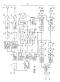
- numeral 1 denotes an input terminal to which is applied a video signal which is to be recorded.
- numeral 2 denotes an A/D converter
- numeral 3 is a signal processing circuit (referred to in the following as a 2-channel divider circuit) which executes time-axis expansion of the input video signal and division of the video signal into two signal channels.
- Numeral 4 denotes a sync separator circuit for separating the sync components of the input video signal
- numeral 5 denotes a timing control circuit which produces a system clock signal, various timing signals, address signals, etc.
- timing control circuit 5 operates in accordance with a sync signal separated from the video signal which is being recorded, while during playback operation circuit 5 operates in accordance with a sync signal that is separated from the playback video signal.
- Numeral 6 denotes a reference signal generating circuit, which generates a reference signal, described hereinafter, at predetermined timings.
- Numerals 7 and 8 denote reference signal insertion circuits, which serve to insert the reference signal into each of the two channels of the divided video signal.
- Numerals 9 and 10 denote D/A converters, 11 and 12 denote FM modulators, 13 and 14 denote recording amplifiers, 15 and 16 denote recording heads, numeral 17 denotes a magnetic tape.
- Numerals 18 and 19 denote playback heads, 20 and 21 denote playback amplifiers, 22 and 23 denote playback equalizers, 24 and 25 denote FM demodulators, 26 and 27 denote filter banks each containing a plurality of band-pass filters (BPFs).
- Numerals 28 and 29 denote detector circuits, 30 and 31 denote A/D converters, 32 denotes a playback signal sync separator circuit, 33 denotes a CPU input interface, 34 denotes a CPU (central processing unit) and 35 denotes an output interface.
- Numerals 36 and 37 denote A/D converters, 38 and 39 denote timebase error corrector circuits (abbreviated in the following to TBCs).
- Numerals 40 and 41 denote time-axis compression circuits, 42 denotes a 2-channel combiner circuit, 43 denotes a D/A converter, and 44 denotes a video signal output terminal. The operation of this embodiment is as follows.
- the video signal which is to be recorded for example a high-definition MUSE standard video signal, is applied to input terminal 1, and is converted to digital form by A/D converter 2.
- the resultant signal is subjected to time-axis expansion, i.e. with each horizontal scanning interval (1H interval) being time-expanded by a factor of 2, and is divided into 2 signal channels.
- Timing control circuit 5 generates a system clock signal by utilizing the separated sync signal from circuit 4 as a timing reference, and also produces timing signals for various signal processing functions.
- the reference signal generating circuit 6 operates under the control of timing control circuit 5 to produce a reference signal having the waveform shown in Fig. 5, in digital signal form, during reference signal insertion timing intervals, e.g. during one 1H interval in each vertical flyback interval.
- the reference signal generating circuit 6 can be readily implemented as a ROM (read-only memory).
- numeral 45 denotes a negative polarity sync signal pulse
- numeral 46 denotes a timing reference signal burst
- the reference signal is composed of a sequential combination of respectively different signal bursts 47 to 51, each having a specific fixed frequency and being superimposed upon a fixed DC level of specific value.
- the term "respectively different signal bursts" as used with respect to the reference signal has the significance "signal bursts of respectively different frequency, or signal bursts superimposed on respectively different DC levels, or signal bursts which respectively differ both in frequency and in superimposed DC level".
- Numeral 47 denotes a signal burst whose frequency is intermediate between the highest and lowest frequencies of the video signal, and which will be referred to in the following as the first medium frequency. This signal burst is superimposed on a DC level corresponding to the black level of the video signal.
- Numeral 48 denotes a signal burst having a frequency which is in the uppermost region of the video signal frequency range, and will be referred to as the high frequency. Burst 48 is also superimposed on the black level of the video signal.
- Numeral 49 denotes a signal burst whose frequency is also intermediate between the highest and lowest frequencies of the video signal, but is higher than the first medium frequency, and which will be referred to as the second medium frequency.
- Burst 49 is superimposed on an intermediate DC level of the video signal.
- Numeral 50 denotes a signal burst at the first medium frequency, which is superimposed on a DC level corresponding to the white level of the video signal.
- Numeral 51 denotes a signal burst at the high frequency, which is also superimposed on the white level.
- the reference signal consisting of the combination of signal bursts shown in Fig. 5, i.e. the signal bursts 47 through 51 superimposed upon their respective DC levels, is inserted into a predetermined lH interval within each vertical blanking interval of each of the two channel-divided time-axis expanded video signals, by the reference signal insertion circuits 7 and 8 respectively.
- the digital signals which are thereby produced from the insertion circuits 7 and 8 are then respectively converted to recording baseband signals by being transferred through D/A converters 9 and l0 respectively, and through low-pass filters (not shown in the drawings), to be then subjected to FM modulation in FM modulator circuits 11 and 12 respectively.
- the modulated signals produced thereby are applied through recording amplifiers 13 and 14 respectively and magnetic recording heads 15 and 16 respectively, to be recorded on magnetic tape 17.
- the playback signals which are produced from playback heads 18 and 19 respectively are amplified by playback amplifiers 20 and 21 respectively.
- the output signals from amplifiers 20 and 21 are transferred through playback equalizers 22 and 23 respectively to be supplied to FM demodulator circuits 24 and 25 respectively, whereby respective baseband signals are produced.
- These baseband signals are applied to the playback signal sync separator circuit 32, and sync signals thereby separated from the baseband signals are applied to control the operation of timing control circuit 5.
- output signals from timing control circuit 5 are applied to filter banks 26 and 27 to control the operation thereof, as described hereinafter.
- the reference signal which is reproduced by playback operation should have the waveform shown in Fig. 5.
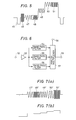
- the playback baseband signals are also applied to filter banks 26 and 27 respectively, each of which has the configuration shown in Fig. 6.
- numeral 52 denotes an input terminal
- 53 denotes a buffer amplifier
- 54 denotes a narrow-band band-pass filter whose passband includes the frequency of signal bursts 47 and 50 (the first medium frequency) of the reference signal shown in Fig.
- 55 denotes a narrow-band band-pass filter whose passband includes the frequency of signal burst 49 (the second medium frequency)
- 56 denotes a narrow-band band-pass filter whose passband includes the frequency of signal bursts 48 and 51 (i.e. the high frequency).
- Numeral 57 denotes an analog multiplexer
- 58 denotes a control terminal of multiplexer 57
- 59 denotes an output terminal.
- the playback reference signal is applied to input terminal 52, to be amplified by buffer amplifier 53, whose output signal is applied to each of filters 54, 55 and 56.
- Control signals are applied to control terminal 58 of multiplexer 57 from timing control circuit 5, (which operates during playback operation in accordance with a sync signal separated from the playback signal, as described above) whereby the outputs from filters 54 through 56 are respectively selected to be transferred to output terminal 59 at predetermined timings, i.e. at timings corresponding to those of signal bursts 47 to 51 in Fig. 5.
- Fig. 7(a) shows an example of the waveform of the signal which is thereby produced from output terminal 59.
- the output signals which are thereby obtained from filter banks 26 and 27 are respectively supplied to detector circuits 28 and 29.
- the resultant output signals from detection circuits 28 and 29 will be of the form shown in Fig. 7(b).
- the DC levels of each of these output signals from the detection circuits will vary in direct proportion to the amplitudes of the signal bursts in the playback reference signal (i.e. bursts 47 ⁇ through 51 ⁇ shown in Fig.. 7(a)).
- the output signals thus produced from detector circuits 28 and 29 are supplied to A/D converters 30 and 31 respectively, to be converted to digital form, and are then read into the microprocessor 34, through the input interface 33.
- the microprocessor 34 performs correction of the equalizer characteristics of the playback equalizers 22 and 23, by means of signals which are applied through the output interface 35, i.e. microprocessor 34 controls the playback equalizers 22 and 23 in a manner such as to make the amplitudes of the signal bursts 47 ⁇ to 51 ⁇ shown in Fig. 7(a) become mutually identical.
- the process of automatic adjustment of the playback equalizers, by utilizing data obtained from the playback reference signal is as follows.
- the spectrum of the recording reference signal shown in Fig. 5, after FM conversion, is shown in Fig. 8.
- the FM carrier frequency is 16 MHz for the black level of the video signal and 20 MHz for the white level
- the high frequency signal bursts of the reference signal have a frequency of 8 MHz
- the first and second medium frequencies of the reference signal signal bursts (as defined with reference to Fig. 5 hereinabove) are 4 MHz and 6 MHz respectively.
- the FM transmission system of the VTR i.e. the overall system, including the recording amplifiers, the heads, the tape, the playback amplifiers, and the playback equalizers
- the waveform shown in Fig. 7(a) is utilized to make the amplitudes of all of the signal bursts in the recording reference signal mutually identical.
- the playback equalizer characteristic which is required to achieve this is shown in the graph at the lower part of Fig. 8, in which frequency is plotted along the horizontal axis, and amount of equalizer compensation along the vertical axis. Amounts of equalizer compensation are indicated in the form a(f), where "f” denotes the frequency at which the compensation is applied (in MHz). Since the frequency characteristic of the input signals to the playback equalizers will change as a result of changes in transmission characteristics due to variations in the tape and the heads as time elapses, it is necessary for the compensation characteristic of each equalizer to change accordingly. Examples of specific values are given in Table 2 below.
- Table 2 shows relative values for the initial playback signal level and for playback signal level after changes (e.g. due to component change as time elapses, as described above) have occurred in the equalizer characteristic, and the playback equalizer output levels before and after such changes in the playback level have occurred. If the playback equalizer output level follows a linear sloping characteristic, then the amplitude of for example signal burst 47 ⁇ shown in Fig. 7(a), corresponding to spectrum A shown in Fig. 8, after FM conversion, is obtained as follows:
- the amplitudes of signal bursts 48 ⁇ to 51 ⁇ are also each made equal to 1, in a similar way.
- ⁇ 0 is the carrier amplitude
- ⁇ -1 is the amplitude of the primary lower sideband
- ⁇ +1 is the amplitude of the primary upper sideband.
- the equalizer characteristic must therefore be varied, by the amounts shown in Table 2 above, such as to make the amplitudes of each of the signal bursts 47 ⁇ to 51 ⁇ become equal to 1.
- Data representing the above signal burst amplitudes are applied through the input interface 33 shown in Fig. 4, and read into CPU 34.
- CPU 34 thereby executes control whereby the playback equalizer output level at 16 MHz is reduced, and the level at 20 MHz is increased, to make the amplitudes of each of signal bursts 47 ⁇ and 51 ⁇ approach a value of 1.
- the amplitude of signal burst 47 ⁇ is made equal to 1 by changing the playback equalizer output level at 16 MHz from 1.46 to 1.20.
- the playback equalizer output level at 20 MHz must be changed from 0.68 to 1.03.
- Adjustment of the playback equalizers is performed utilizing data obtained from the playback reference signal through the process described above, whereby changes in the VTR frequency characteristic resulting from variations in the heads and tape, etc. as time elapses can be corrected, and whereby differences in frequency characteristics between the signal channels are eliminated. Enhanced playback quality is thereby attained.
- the embodiment of the present invention described above relates to a VTR which employs multi-channel recording, by dividing a video signal between a plurality of channels.
- the present invention is equally applicable to single-channel recording, and will provide similar advantages in such applications.
- This problem can be overcome by applying the method of the present invention described above to only a single channel.
- the present invention is highly applicable to FM recording in which a video signal is divided into a plurality of channels for recording and playback, since differences between the frequency characteristics of respectively playback video signal channel signals resulting from differences between the FM transmission characteristics of the channels can be automatically compensated.
- the reference signal of the embodiment described hereinabove consists of a combination of a plurality of different types of signal bursts, each having a specific frequency and a specific DC level, with this combination of signal bursts being inserted within one horizontal scanning interval.
- each signal burst i.e. having a specific frequency and DC level
- the reference signal would consist of a plurality of horizontal scanning intervals of the video signal, containing respective signal bursts each of predetermined frequency and superimposed on a predetermined DC level, with the burst frequency and DC level being held constant during each horizontal scanning interval.
- Such an arrangement has the advantage that greater accuracy of detection of the amplitudes of the signal bursts in the playback signal can be obtained, since each burst continues for a greater length of time.
- the five different signal bursts of the embodiment described above would be respectively inserted into five different horizontal scanning intervals of the video signal.
Landscapes
- Engineering & Computer Science (AREA)
- Multimedia (AREA)
- Signal Processing (AREA)
- Television Signal Processing For Recording (AREA)
Claims (6)
- Verfahren für Videosignalaufzeichnung und -wiedergabe, das die Verfahrensschritte beinhaltet:
Einfügen eines Bezugssignals in Austastlücken eines aufzuzeichnenden Videosignals und Durchführen einer frequenzmodulierten Aufzeichnung des Bezugssignals gemeinsam mit dem Videosignal auf einen Aufzeichnungsträger, wobei das Bezugssignal eine Kombination aus einer Vielzahl von Signalimpulsen enthält, von denen jedes eine charakteristische Frequenz aufweist und von denen jedes mit einem Gleichstrompegel charakteristischen Wertes überlagert ist, wobei die Vielzahl von Signalimpulsen Signalimpulse mit untereinander unterschiedlicher Frequenz aufweisen;
Wiedergabe vom Aufzeichnungsträger, um ein frequenzmoduliertes Wiedergabesignal zu erlangen, Durchschleusen des frequenzmodulierten Wiedergabesignals durch einen Wiedergabeentzerrer, um ein demoduliertes Wiedergabesignal zu erlangen, Abtrennen eines Wiedergabe-Bezugssignals aus dem demodulierten Wiederabesignal und Feststellen betreffender Amplituden der Signalimpulse im Wiedergabebezugssignal; und
Steuern des Wiedergabeentzerrers in der Weise, daß die gegenseitigen Verhältnisse zwischen dem Signalimpuls-Amplituden des Wiedergabe-Bezugssignals im wesentlichen mit den gegenseitigen Verhältnissen zwischen Amplituden der Signalimpulse des Bezugssignals vor der Aufzeichnung auf den Träger übereinstimmen. - Verfahren nach Anspruch 1, das des weiteren den zusätzlichen Verfahrenschritt beinhaltet:
Aufteilen eines aufzunehmenden Videosignals in eine Vielzahl von Kanälen; und in dem das Bezugssignal eingeführt wird in die Austastlücken der aufgeteilten Videosignale betreffender Kanäle. - Verfahren für Videosignalaufzeichnung und -wiedergabe nach Anspruch 1 oder 2, in dem eine Vielzahl der Signalimpulse des Bezugssignals innerhalb eines Abtastintervalls des Videosignals kombiniert werden.
- Verfahren für Videosignalaufzeichnung und - wiedergabe nach Anspruch 1 oder 2, in dem betreffende der Signalimpulse des Bezugssignals eingefügt werden in betreffende Horizontal-Austastintervalle des Videosignals, wobei das Bezugssignal eine Kombination verschiedener der in einer Vielzahl der Horizontal-Austastintervallen enthaltenen Signalimpulse einschließt.
- Vorrichtung für Videosignalaufzeichnung und -wiedergabe mit:
einem Generator für ein Bezugssignal, das eine Kombination aus einer Vielzahl von Signalimpulsen enthält, von denen jedes eine charakteristische Frequenz aufweist, und von denen jedes mit einem Gleichstrompegel charakteristischen Wertes überlagert ist, wobei die Vielzahl von Signalimpulsen Signalimpulse mit untereinander verschiedener Frequenz aufweisen;
Mitteln zum Einfügen des Bezugssignals in ein erstes Videosignal, um ein zweites Videosignal zu erzeugen;
einem Frequenzmodulator für das zweite Videosignal, der ein frequenzmoduliertes Signal erzeugt;
Mitteln zur Aufzeichnung des frequenzmodulierten Signals aus einem Aufzeichnungsträger, um ein Wiedergabesignal zu erlangen;
einem Wiedergabeentzerrer, der einen Frequenzgang des Wiedergabesignals elektrisch beeinflußt;
einem Frequenzmodulator für das Wiedergabesignal zur Gewinnung eines demodulierten Wiedergabesignals;
Mitteln zum Abtrennen des Bezugssignals vom demodulierten Wiedergabesignal;
Mitteln zum Feststellen betreffender Amplituden der Signalimpulse im Bezugssignal nach der Abtrennung, die die Amplituden repräsentierende Daten bilden; und mit
Verarbeitungsmitteln, die zum Empfang der Daten angekoppelt sind, um die Daten vorherbestimmten Verarbeitungsschritten zu unterziehen und um eine automatische Frequenzgang-Steuerung des Wiedergabeentzerrers abhängig von Verarbeitungsergebnissen zu erreichen. - Vorrichtung für Videosignalaufzeichnung und- wiedergabe nach Anspruch 5, die weiterhin Mittel zur Aufteilung des ersten Videosignals in eine Vielzahl von Kanalsignalen enthält, sowie Mittel zum Einfügen des Bezugssignals in ein jedes der Kanalsignale.
Applications Claiming Priority (2)
| Application Number | Priority Date | Filing Date | Title |
|---|---|---|---|
| JP77116/86 | 1986-04-03 | ||
| JP61077116A JPS62233990A (ja) | 1986-04-03 | 1986-04-03 | 映像信号記録再生方法 |
Publications (3)
| Publication Number | Publication Date |
|---|---|
| EP0241227A2 EP0241227A2 (de) | 1987-10-14 |
| EP0241227A3 EP0241227A3 (en) | 1989-01-25 |
| EP0241227B1 true EP0241227B1 (de) | 1993-02-17 |
Family
ID=13624815
Family Applications (1)
| Application Number | Title | Priority Date | Filing Date |
|---|---|---|---|
| EP87302890A Revoked EP0241227B1 (de) | 1986-04-03 | 1987-04-02 | Verfahren und Vorrichtung für Videosignalaufzeichnung und -wiedergabe |
Country Status (4)
| Country | Link |
|---|---|
| US (1) | US4807056A (de) |
| EP (1) | EP0241227B1 (de) |
| JP (1) | JPS62233990A (de) |
| DE (1) | DE3784180T2 (de) |
Families Citing this family (21)
| Publication number | Priority date | Publication date | Assignee | Title |
|---|---|---|---|---|
| EP0321181B1 (de) * | 1987-12-14 | 1994-03-09 | Mitsubishi Denki Kabushiki Kaisha | Charakteristikkorrektionsgerät |
| EP0332381A1 (de) * | 1988-03-08 | 1989-09-13 | Matsushita Electric Industrial Co., Ltd. | Aufzeichnungs- und Wiedergabegerät für Videosignale |
| JP2570377B2 (ja) * | 1988-04-07 | 1997-01-08 | ソニー株式会社 | 磁気記録および/または再生装置 |
| JPH02134093A (ja) * | 1988-11-15 | 1990-05-23 | Toshiba Corp | 映像再生装置 |
| JP2706495B2 (ja) * | 1988-11-22 | 1998-01-28 | 松下電器産業株式会社 | 画像信号処理装置 |
| DE3903165A1 (de) * | 1989-02-03 | 1990-08-09 | Thomson Brandt Gmbh | Magnetbandgeraet zur digitalen aufzeichnung und wiedergabe von audio- bzw. videosignalen |
| US5083211A (en) * | 1989-06-23 | 1992-01-21 | Eastman Kodak Company | Method and apparatus for optimizing video recording and reproduction |
| GB9000105D0 (en) * | 1990-01-03 | 1990-03-07 | Racal Recorders Ltd | Recording system |
| JP2800373B2 (ja) * | 1990-05-31 | 1998-09-21 | 松下電器産業株式会社 | 磁気録画再生装置の自動画質調整装置 |
| US5249064A (en) * | 1990-07-02 | 1993-09-28 | Akai Electric Co., Ltd. | Noise canceller for use in a magnetic reproducing apparatus |
| US5257109A (en) * | 1990-07-02 | 1993-10-26 | Akai Electric Co., Ltd. | Magnetic recording and reproducing apparatus |
| JPH0498602A (ja) * | 1990-08-14 | 1992-03-31 | Sony Corp | 再生装置 |
| JP2529454B2 (ja) * | 1990-09-14 | 1996-08-28 | 松下電器産業株式会社 | 記録再生装置 |
| JPH06111596A (ja) * | 1990-10-09 | 1994-04-22 | Texas Instr Inc <Ti> | メモリ |
| JP3093255B2 (ja) * | 1990-10-31 | 2000-10-03 | キヤノン株式会社 | ビデオ信号記録装置 |
| US5663844A (en) * | 1990-11-19 | 1997-09-02 | Canon Kabushiki Kaisha | Signal reproducing apparatus having waveform equalizing function |
| JP2948697B2 (ja) * | 1992-06-25 | 1999-09-13 | キヤノン株式会社 | 再生装置 |
| DE69322703T2 (de) * | 1992-07-17 | 1999-07-22 | Mitsubishi Denki K.K., Tokio/Tokyo | Kontrollanordnung für magnetische Aufzeichnung |
| JPH06197313A (ja) * | 1992-09-28 | 1994-07-15 | Victor Co Of Japan Ltd | 磁気記録再生装置 |
| US5579119A (en) * | 1992-10-19 | 1996-11-26 | Mitsubishi Denki Kabushiki Kaisha | Recording signal control apparatus capable of optimizing recording conditions for magnetic recording medium |
| KR950006083B1 (ko) * | 1993-03-05 | 1995-06-08 | 주식회사엘지전자 | 브이 씨 알(vcr)의 알 에프(rf)신호 레벨 자동 조절장치 |
Citations (3)
| Publication number | Priority date | Publication date | Assignee | Title |
|---|---|---|---|---|
| EP0114694A2 (de) * | 1983-01-25 | 1984-08-01 | Robert Bosch Gmbh | System zur Übertragung eines breitbandigen Farbvideosignals |
| DE3404648A1 (de) * | 1983-02-09 | 1984-08-16 | Victor Company Of Japan, Ltd., Yokohama, Kanagawa | Aufzeichnungssignal-erzeugungssystem fuer farbvideosignale |
| JPS6146681A (ja) * | 1984-08-11 | 1986-03-06 | Matsushita Electric Ind Co Ltd | 映像信号の記録再生方法 |
Family Cites Families (7)
| Publication number | Priority date | Publication date | Assignee | Title |
|---|---|---|---|---|
| US3576390A (en) * | 1968-05-29 | 1971-04-27 | Rca Corp | Apparatus for generating test signals useful in measuring television transmission performance without affecting receiver synchronization |
| US3643013A (en) * | 1970-10-08 | 1972-02-15 | Ampex | Dual loop equalization for a frequency modulated signal system |
| US3852808A (en) * | 1973-04-04 | 1974-12-03 | Rca Corp | Color amplitude correction in plural transducer signal playback systems |
| JPS5081517A (de) * | 1973-11-20 | 1975-07-02 | ||
| DE2933004C2 (de) * | 1978-08-16 | 1984-03-15 | Hitachi, Ltd., Tokyo | Tonbandgerät mit verbesserter Frequenzgangentzerrung |
| JPS5990477A (ja) * | 1982-11-16 | 1984-05-24 | Sony Corp | ビデオ信号補正回路 |
| JPS6141284A (ja) * | 1984-08-02 | 1986-02-27 | Matsushita Electric Ind Co Ltd | 磁気記録再生装置 |
-
1986
- 1986-04-03 JP JP61077116A patent/JPS62233990A/ja active Pending
-
1987
- 1987-04-02 EP EP87302890A patent/EP0241227B1/de not_active Revoked
- 1987-04-02 DE DE8787302890T patent/DE3784180T2/de not_active Expired - Fee Related
- 1987-04-02 US US07/033,469 patent/US4807056A/en not_active Expired - Lifetime
Patent Citations (3)
| Publication number | Priority date | Publication date | Assignee | Title |
|---|---|---|---|---|
| EP0114694A2 (de) * | 1983-01-25 | 1984-08-01 | Robert Bosch Gmbh | System zur Übertragung eines breitbandigen Farbvideosignals |
| DE3404648A1 (de) * | 1983-02-09 | 1984-08-16 | Victor Company Of Japan, Ltd., Yokohama, Kanagawa | Aufzeichnungssignal-erzeugungssystem fuer farbvideosignale |
| JPS6146681A (ja) * | 1984-08-11 | 1986-03-06 | Matsushita Electric Ind Co Ltd | 映像信号の記録再生方法 |
Non-Patent Citations (7)
| Title |
|---|
| "ELECTRONICS AND POWER, June 1964; N.W. LEWIS: "PROPOSED SUBCARRIER PILOT FOR NTSC-TYPE COLOUR TELEVISION" (cited by the Proprietor) * |
| "FACHWÖRTERBUCH DES NACHRICHTENWESENS", 1980, pages 174 and 175, Fachverlag Schiele & Schön, Berlin, Germany * |
| "FERNSEHMESSTECHNIK", W. DILLENBURGER, 1972, PAGES 438-440, Fachverlag Schiele & Schön, Berlin, Germany * |
| "FERNSEHTECHNIK", R. THEILE, 1973, PAGES 117, 118, 157, Springer- Verlag, Berlin, Germany * |
| 10. JAHRESTAGUNG DER FKTG - TAGUNGSBAND, 13 to 17 September 1982, MUNICH, GERMANY, pages 168-181; H. HAFRANKE ET AL.: "AUTOMATISCHE ÜBERWACHUNG UND KORREKTUR DER ÜBERTRAGUNGSWEGE IM FERNSEHSTUDIO MITTELS PRÜFZEILEN" * |
| 8. JAHRESTAGUNG DER FKTG - TAGUNGSBAND, 06 to 09 October 980, BERLIN, GERMANY, pages 207-217; G. BRAND ET AL.: "TIMEPLEX - EIN FARBCODIERVERFAHREN FÜR VIDEORECORDER" * |
| RUNDFUNKTECHNISCHE MITTEILUNGEN, vol. 12, no. 2, 1968, pages 76-80; P. FASSHAUER: P. FASSHAUER: "ABLEITUNG VON STEUERSPANNUNGEN AUS PRÜFZELLENIMPULSEN" * |
Also Published As
| Publication number | Publication date |
|---|---|
| US4807056A (en) | 1989-02-21 |
| EP0241227A2 (de) | 1987-10-14 |
| DE3784180T2 (de) | 1993-08-05 |
| EP0241227A3 (en) | 1989-01-25 |
| JPS62233990A (ja) | 1987-10-14 |
| DE3784180D1 (de) | 1993-03-25 |
Similar Documents
| Publication | Publication Date | Title |
|---|---|---|
| US4807056A (en) | Method and apparatus for video signal recording and playback signal level compensation based on recorded reference signal | |
| US5404248A (en) | Video data recording/reproducing apparatus with efficient error correction | |
| US4458271A (en) | Method and circuit for the transmitting, recording, and/or reproducing of wide-band signals | |
| US5294979A (en) | Estimation of noise using burst gate response to video signal | |
| US5124850A (en) | Method and apparatus for equalizing fm video signals using variable equalizer | |
| US4731674A (en) | Color video signal processing apparatus for crosstalk elimination | |
| US3938179A (en) | Comb filter for video processing | |
| JPS60100893A (ja) | 時間順次伝送方式 | |
| GB2103906A (en) | Time axis correction device for multiplex information-carrying signal obtained from recording medium | |
| EP0486300B1 (de) | Verarbeitungssystem für Videosignale | |
| US5166803A (en) | Image signal recording and reproducing system | |
| JPS61181286A (ja) | 画像信号のデイジタル記録装置 | |
| JPS628680A (ja) | 映像信号記録再生装置 | |
| KR900001450B1 (ko) | 기록 재생 장치 | |
| JP2780730B2 (ja) | 映像信号交番重畳及び広げ回路 | |
| JPS60217787A (ja) | 映像信号の記録装置と記録再生装置 | |
| JPS60170393A (ja) | 映像信号の記録再生装置 | |
| JPH0666960B2 (ja) | クロマ信号記録再生方法 | |
| JP2532454B2 (ja) | 映像信号記録再生装置 | |
| JPS6364488A (ja) | 磁気記録再生方式 | |
| JPS62294387A (ja) | 映像信号記録再生方法 | |
| Iwamura et al. | Video signal processing in HD VCR for baseband/MUSE analog recording | |
| JPS6370690A (ja) | 録画再生装置 | |
| JPH028518B2 (de) | ||
| JPH0224437B2 (de) |
Legal Events
| Date | Code | Title | Description |
|---|---|---|---|
| PUAI | Public reference made under article 153(3) epc to a published international application that has entered the european phase |
Free format text: ORIGINAL CODE: 0009012 |
|
| 17P | Request for examination filed |
Effective date: 19870424 |
|
| AK | Designated contracting states |
Kind code of ref document: A2 Designated state(s): DE FR GB NL |
|
| PUAL | Search report despatched |
Free format text: ORIGINAL CODE: 0009013 |
|
| AK | Designated contracting states |
Kind code of ref document: A3 Designated state(s): DE FR GB NL |
|
| 17Q | First examination report despatched |
Effective date: 19910415 |
|
| GRAA | (expected) grant |
Free format text: ORIGINAL CODE: 0009210 |
|
| AK | Designated contracting states |
Kind code of ref document: B1 Designated state(s): DE FR GB NL |
|
| REF | Corresponds to: |
Ref document number: 3784180 Country of ref document: DE Date of ref document: 19930325 |
|
| ET | Fr: translation filed | ||
| PLBI | Opposition filed |
Free format text: ORIGINAL CODE: 0009260 |
|
| 26 | Opposition filed |
Opponent name: INTERESSENGEMEINSCHAFT FUER RUNDFUNKSCHUTZRECHTE E Effective date: 19931118 |
|
| NLR1 | Nl: opposition has been filed with the epo |
Opponent name: INTERESSENGEMEINSCHAFT FUER RUNDFUNKSCHUTZRECHTE E |
|
| PGFP | Annual fee paid to national office [announced via postgrant information from national office to epo] |
Ref country code: GB Payment date: 19940331 Year of fee payment: 8 |
|
| PGFP | Annual fee paid to national office [announced via postgrant information from national office to epo] |
Ref country code: DE Payment date: 19940408 Year of fee payment: 8 |
|
| PGFP | Annual fee paid to national office [announced via postgrant information from national office to epo] |
Ref country code: FR Payment date: 19940411 Year of fee payment: 8 |
|
| PGFP | Annual fee paid to national office [announced via postgrant information from national office to epo] |
Ref country code: NL Payment date: 19940430 Year of fee payment: 8 |
|
| PG25 | Lapsed in a contracting state [announced via postgrant information from national office to epo] |
Ref country code: GB Effective date: 19950402 |
|
| PLAB | Opposition data, opponent's data or that of the opponent's representative modified |
Free format text: ORIGINAL CODE: 0009299OPPO |
|
| R26 | Opposition filed (corrected) |
Opponent name: INTERESSENGEMEINSCHAFT FUER RUNDFUNKSCHUTZRECHTE E Effective date: 19931118 |
|
| NLR1 | Nl: opposition has been filed with the epo |
Opponent name: INTERESSENGEMEINSCHAFT FUER RUNDFUNKSCHUTZRECHTE E |
|
| PG25 | Lapsed in a contracting state [announced via postgrant information from national office to epo] |
Ref country code: NL Effective date: 19951101 |
|
| GBPC | Gb: european patent ceased through non-payment of renewal fee |
Effective date: 19950402 |
|
| PG25 | Lapsed in a contracting state [announced via postgrant information from national office to epo] |
Ref country code: FR Effective date: 19951229 |
|
| NLV4 | Nl: lapsed or anulled due to non-payment of the annual fee |
Effective date: 19951101 |
|
| PG25 | Lapsed in a contracting state [announced via postgrant information from national office to epo] |
Ref country code: DE Effective date: 19960103 |
|
| REG | Reference to a national code |
Ref country code: FR Ref legal event code: ST |
|
| PLAW | Interlocutory decision in opposition |
Free format text: ORIGINAL CODE: EPIDOS IDOP |
|
| PLAW | Interlocutory decision in opposition |
Free format text: ORIGINAL CODE: EPIDOS IDOP |
|
| RDAH | Patent revoked |
Free format text: ORIGINAL CODE: EPIDOS REVO |
|
| RDAG | Patent revoked |
Free format text: ORIGINAL CODE: 0009271 |
|
| STAA | Information on the status of an ep patent application or granted ep patent |
Free format text: STATUS: PATENT REVOKED |
|
| 27W | Patent revoked |
Effective date: 19970726 |