EP0241255A1 - Système numérique de traitement d'image et procédé - Google Patents
Système numérique de traitement d'image et procédé Download PDFInfo
- Publication number
- EP0241255A1 EP0241255A1 EP87302991A EP87302991A EP0241255A1 EP 0241255 A1 EP0241255 A1 EP 0241255A1 EP 87302991 A EP87302991 A EP 87302991A EP 87302991 A EP87302991 A EP 87302991A EP 0241255 A1 EP0241255 A1 EP 0241255A1
- Authority
- EP
- European Patent Office
- Prior art keywords
- site
- digital image
- image processing
- processing equipment
- data
- Prior art date
- Legal status (The legal status is an assumption and is not a legal conclusion. Google has not performed a legal analysis and makes no representation as to the accuracy of the status listed.)
- Granted
Links
- 238000012545 processing Methods 0.000 title claims abstract description 52
- 238000000034 method Methods 0.000 title claims description 20
- 238000012544 monitoring process Methods 0.000 claims description 16
- 230000004044 response Effects 0.000 claims description 6
- 238000004458 analytical method Methods 0.000 abstract description 33
- 238000004891 communication Methods 0.000 description 17
- 238000009434 installation Methods 0.000 description 8
- 230000009471 action Effects 0.000 description 3
- 238000010586 diagram Methods 0.000 description 3
- 230000000737 periodic effect Effects 0.000 description 2
- 238000012546 transfer Methods 0.000 description 2
- 230000005540 biological transmission Effects 0.000 description 1
- 230000015556 catabolic process Effects 0.000 description 1
- 238000012937 correction Methods 0.000 description 1
- 238000002405 diagnostic procedure Methods 0.000 description 1
- 238000005516 engineering process Methods 0.000 description 1
- 230000006870 function Effects 0.000 description 1
- 238000011850 initial investigation Methods 0.000 description 1
- 238000003780 insertion Methods 0.000 description 1
- 230000037431 insertion Effects 0.000 description 1
- 238000012423 maintenance Methods 0.000 description 1
- 238000004519 manufacturing process Methods 0.000 description 1
- 238000012986 modification Methods 0.000 description 1
- 230000004048 modification Effects 0.000 description 1
- 230000003287 optical effect Effects 0.000 description 1
- 230000008569 process Effects 0.000 description 1
- 230000008672 reprogramming Effects 0.000 description 1
- 238000012360 testing method Methods 0.000 description 1
- 230000000007 visual effect Effects 0.000 description 1
Images


Classifications
-
- H—ELECTRICITY
- H04—ELECTRIC COMMUNICATION TECHNIQUE
- H04N—PICTORIAL COMMUNICATION, e.g. TELEVISION
- H04N1/00—Scanning, transmission or reproduction of documents or the like, e.g. facsimile transmission; Details thereof
- H04N1/0035—User-machine interface; Control console
- H04N1/00405—Output means
- H04N1/00408—Display of information to the user, e.g. menus
-
- H—ELECTRICITY
- H04—ELECTRIC COMMUNICATION TECHNIQUE
- H04N—PICTORIAL COMMUNICATION, e.g. TELEVISION
- H04N1/00—Scanning, transmission or reproduction of documents or the like, e.g. facsimile transmission; Details thereof
- H04N1/00002—Diagnosis, testing or measuring; Detecting, analysing or monitoring not otherwise provided for
- H04N1/00005—Diagnosis, testing or measuring; Detecting, analysing or monitoring not otherwise provided for relating to image data
-
- H—ELECTRICITY
- H04—ELECTRIC COMMUNICATION TECHNIQUE
- H04N—PICTORIAL COMMUNICATION, e.g. TELEVISION
- H04N1/00—Scanning, transmission or reproduction of documents or the like, e.g. facsimile transmission; Details thereof
- H04N1/00002—Diagnosis, testing or measuring; Detecting, analysing or monitoring not otherwise provided for
- H04N1/00007—Diagnosis, testing or measuring; Detecting, analysing or monitoring not otherwise provided for relating to particular apparatus or devices
- H04N1/00013—Reading apparatus
-
- H—ELECTRICITY
- H04—ELECTRIC COMMUNICATION TECHNIQUE
- H04N—PICTORIAL COMMUNICATION, e.g. TELEVISION
- H04N1/00—Scanning, transmission or reproduction of documents or the like, e.g. facsimile transmission; Details thereof
- H04N1/00002—Diagnosis, testing or measuring; Detecting, analysing or monitoring not otherwise provided for
- H04N1/00007—Diagnosis, testing or measuring; Detecting, analysing or monitoring not otherwise provided for relating to particular apparatus or devices
- H04N1/00015—Reproducing apparatus
-
- H—ELECTRICITY
- H04—ELECTRIC COMMUNICATION TECHNIQUE
- H04N—PICTORIAL COMMUNICATION, e.g. TELEVISION
- H04N1/00—Scanning, transmission or reproduction of documents or the like, e.g. facsimile transmission; Details thereof
- H04N1/00002—Diagnosis, testing or measuring; Detecting, analysing or monitoring not otherwise provided for
- H04N1/00026—Methods therefor
- H04N1/00029—Diagnosis, i.e. identifying a problem by comparison with a normal state
-
- H—ELECTRICITY
- H04—ELECTRIC COMMUNICATION TECHNIQUE
- H04N—PICTORIAL COMMUNICATION, e.g. TELEVISION
- H04N1/00—Scanning, transmission or reproduction of documents or the like, e.g. facsimile transmission; Details thereof
- H04N1/00002—Diagnosis, testing or measuring; Detecting, analysing or monitoring not otherwise provided for
- H04N1/00026—Methods therefor
- H04N1/00042—Monitoring, i.e. observation
-
- H—ELECTRICITY
- H04—ELECTRIC COMMUNICATION TECHNIQUE
- H04N—PICTORIAL COMMUNICATION, e.g. TELEVISION
- H04N1/00—Scanning, transmission or reproduction of documents or the like, e.g. facsimile transmission; Details thereof
- H04N1/00002—Diagnosis, testing or measuring; Detecting, analysing or monitoring not otherwise provided for
- H04N1/00026—Methods therefor
- H04N1/00045—Methods therefor using a reference pattern designed for the purpose, e.g. a test chart
-
- H—ELECTRICITY
- H04—ELECTRIC COMMUNICATION TECHNIQUE
- H04N—PICTORIAL COMMUNICATION, e.g. TELEVISION
- H04N1/00—Scanning, transmission or reproduction of documents or the like, e.g. facsimile transmission; Details thereof
- H04N1/00002—Diagnosis, testing or measuring; Detecting, analysing or monitoring not otherwise provided for
- H04N1/00026—Methods therefor
- H04N1/0005—Methods therefor in service, i.e. during normal operation
-
- H—ELECTRICITY
- H04—ELECTRIC COMMUNICATION TECHNIQUE
- H04N—PICTORIAL COMMUNICATION, e.g. TELEVISION
- H04N1/00—Scanning, transmission or reproduction of documents or the like, e.g. facsimile transmission; Details thereof
- H04N1/00002—Diagnosis, testing or measuring; Detecting, analysing or monitoring not otherwise provided for
- H04N1/00026—Methods therefor
- H04N1/00053—Methods therefor out of service, i.e. outside of normal operation
-
- H—ELECTRICITY
- H04—ELECTRIC COMMUNICATION TECHNIQUE
- H04N—PICTORIAL COMMUNICATION, e.g. TELEVISION
- H04N1/00—Scanning, transmission or reproduction of documents or the like, e.g. facsimile transmission; Details thereof
- H04N1/00002—Diagnosis, testing or measuring; Detecting, analysing or monitoring not otherwise provided for
- H04N1/00026—Methods therefor
- H04N1/00055—Methods therefor automatically on a periodic basis
-
- H—ELECTRICITY
- H04—ELECTRIC COMMUNICATION TECHNIQUE
- H04N—PICTORIAL COMMUNICATION, e.g. TELEVISION
- H04N1/00—Scanning, transmission or reproduction of documents or the like, e.g. facsimile transmission; Details thereof
- H04N1/00002—Diagnosis, testing or measuring; Detecting, analysing or monitoring not otherwise provided for
- H04N1/00026—Methods therefor
- H04N1/00058—Methods therefor using a separate apparatus
-
- H—ELECTRICITY
- H04—ELECTRIC COMMUNICATION TECHNIQUE
- H04N—PICTORIAL COMMUNICATION, e.g. TELEVISION
- H04N1/00—Scanning, transmission or reproduction of documents or the like, e.g. facsimile transmission; Details thereof
- H04N1/00002—Diagnosis, testing or measuring; Detecting, analysing or monitoring not otherwise provided for
- H04N1/00071—Diagnosis, testing or measuring; Detecting, analysing or monitoring not otherwise provided for characterised by the action taken
- H04N1/00074—Indicating or reporting
- H04N1/00079—Indicating or reporting remotely
-
- H—ELECTRICITY
- H04—ELECTRIC COMMUNICATION TECHNIQUE
- H04N—PICTORIAL COMMUNICATION, e.g. TELEVISION
- H04N1/00—Scanning, transmission or reproduction of documents or the like, e.g. facsimile transmission; Details thereof
- H04N1/32—Circuits or arrangements for control or supervision between transmitter and receiver or between image input and image output device, e.g. between a still-image camera and its memory or between a still-image camera and a printer device
Definitions
- the invention relates to digital image processing systems and methods of monitoring digital image processing equipment.
- Such equipment includes digital input scanners for scanning a transparency or the like to generate digital data representing the pixel content of that transparency, digital output scanners for exposing a record medium to an exposing beam such as a laser beam controlled in response to digital data representing the pixel content of the output image, and digital image modification systems enabling scanned images to be retouched and modified as well as enabling pages to be composed.
- digital input scanners for scanning a transparency or the like to generate digital data representing the pixel content of that transparency
- digital output scanners for exposing a record medium to an exposing beam such as a laser beam controlled in response to digital data representing the pixel content of the output image
- digital image modification systems enabling scanned images to be retouched and modified as well as enabling pages to be composed.
- JP-A-583466 discloses a monitoring system for monitoring data transferred between a pair of transmission systems.
- EP-A-0159158 discloses a facsimile system having a local host processor system for controlling a facsimile unit.
- a digital image processing system comprises processing means at a first site; and digital image processing equipment at a second site remote from the first site, the processing means and the digital image processing equipment being connectable and being adapted to pass signals therebetween corresponding to signals generated by the digital image processing equipment.
- This system enables a variety of monitoring and/or control processes to be achieved from the first site.
- This means that an engineer may be located at a central site and be responsible for a large number of widely separated sets of digital image processing equipment at a plurality of second sites.
- the processing means at the first site may be adapted simply to receive signals from the digital image processing equipment at the second site.
- the processing means and the digital image processing equipment are adapted to pass signals in both directions therebetween. This latter arrangement enables the engineer at the first site not only to monitor the action taken at the second site but also to control directly the digital image processing equipment.
- the system further comprises storage means for storing a history of the operator commands generated at the second site. This enables the engineer at the first site to monitor the sequence of commands issued at the second site in order to check that the equipment is being instructed correctly by the operator.
- the storage means is preferable sited at the second site.
- the processing means can monitor operator commands generated at the second site in real time as these commands are generated.
- the signals passed to the first site from the second site may be representative of operator commands generated at the second site, digital data generated by the image processing equipment, for example as a result of scanning an image, power supply voltages, laser power and current, input optical and electronic calibration parameters and the like.
- the digital image processing equipment includes a monitoring system including a processor responsive to a programme stored within the monitoring system, the processing means being adapted to modify the stored programme.
- the programme which can be modified is stored in electrically erasable programmable read only memory (EEPROM) while the software enabling this reprogramming to be achieved is itself stored in non-alterable EPROM.
- EEPROM electrically erasable programmable read only memory
- the processing means at the first site includes at least logic circuitry and preferably a microprocessor and is not simply a slave terminal for connection with the digital image processing equipment.
- connection between the two sites may be a permanent hard wired connection or could be provided on an intermittent basis via, for example, the public switched telephone network.
- a method of monitoring at a first site digital image processing equipment at a second site remote from the first site, the digital image processing equipment being responsive to operator commands at the second site to generate digital image data comprises storing a history of operator commands and/or digital data generated by the digital image processing equipment; and displaying all or part of the history at the first site.
- This aspect of the invention deals with one of the problems set out above where a relatively inexperienced operator is incorrectly operating the equipment. Furthermore, it does not require an engineer to travel to the remote second site since instead he can remain at the first, central site and monitor the remote equipment. In addition, by positioning the engineer at the first site he can monitor equipment at a number of second sites which may be widely spaced apart from each other and from the central site.
- the step of storing a history of the operator commands and/or digital data is carried out at the second site, the history being transmitted to the first site in response to a suitable command.
- a suitable command For example, when a problem is encountered, the engineer at the first site could issue a command to the remote equipment via a communications link to be described below causing the remote equipment to transmit the history of commands or digital data.
- the digital image processing equipment at the second site may include a store, such as a RAM; and means for detecting operator commands and/or digital data and causing the store to store corresponding representations.
- a store such as a RAM
- the store could comprise a first in-first out store.
- a method of monitoring at a first site digital image processing equipment at a second site remote from the first site comprises transmitting to the first site a signal representative of one or more of the operator commands and data generated by the equipment as the commands or data is generated at the second site; and monitoring at the first site the transmitted signals.
- This method enables the operation of the equipment to be monitored at the first site in real time. It also enables two types of diagnostic information to be obtained. Firstly, the engineer at the first site is able to determine whether an operator is issuing an incorrect series of commands and secondly he is able, in conjunction with the operator at the remote, second site, to determine whether there is a fault with the image processing equipment in that it responds incorrectly to particular commands. Thus, having ascertained that a correct series of commands have been issued, the engineer can communicate with the operator to assess what actions the equipment is taking in response to those commands. The communication can be by voice, or could be a message transmitted from the first site to the second site and displayed by the image processing equipment.
- a method of monitoring at a first site digital image input scanning equipment at a second site remote from the first site comprises causing the input scanning equipment to scan a line of an image whose pixel content is already known to generate scanned digital data; transmitting information related to the scanned digital data to the first site; and comparing the transmitted information with expected information to monitor for any errors in the scanned line.
- the line of known characteristics may be taken from a standard vignette of grey scale which will be fitted by the operator at the second site to the input scanner.
- this method further comprises comparing, at the second site, the scanned digital data with one or more thresholds and transmitting to the first site only information relating to excursions of the data outside the or each threshold.
- This is particularly useful where a large number of pixels in a scan line are concerned. For example, a single line of an A4 page may comprise 16000 pixels requiring up to ten minutes to transmit the scanned digital data between the two sites.
- By comparing the scanned line with preferably two thresholds it is possible only to send information relating to excursions of the scanned data outside the band defined by the thresholds. This will indicate the errors which the operator had detected or wishes to correct.
- the known image line is repeatedly scanned so that random deviations in the scanned pixel content can be eliminated.
- Communication between the sites may be achieved in any conventional manner by for example a fixed link or a radio link. However, it is preferable if communication is achieved using the public switched telephone network, the equipment at both sites being provided with conventional modems or similar equipment.
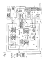
- the customer installation comprises a conventional analyse scanner 1 for scanning original transparencies and generating digital data defining the colour content of pixels of the transparencies and a conventional expose scanner 2 responsive to digital data to control the exposure of a record medium to an exposing laser beam.
- Typical scanners 1, 2 are those manufactured by Crosfield Electronics Ltd under the tradename Magnascan.
- the analyse scanner 1 is connected to a diagnostic analyse printed circuit board 3 while the expose scanner is connected to a diagnostic expose printed circuit board 4.
- the circuit board 3 is connected directly to a modem 5 while the circuit board 4 is connected to the modem 5 via the circuit board 3.
- the scanners are connected directly to one another for the transfer of digital image data and control data by respective buses 11, 12 (shown as one bus in Figure 1)
- the modem 5 is connected to a conventional telephone line 6 which connects with a modem 7 at a central customer support site remote from the customer installation when dialled from the central support site.
- the support site includes a central processing unit 8 connected to the modem 7, a keyboard 9 similar to the keyboards included in the analyse and expose scanners 1, 2 and a monitor 10.
- the anlayse scanner includes a keyboard 13 for controlling operation of the scanner, the keyboard incorporating a central processing unit (CPU) 14.
- the analyse scanner also includes a control system 15 including a system control CPU 16 and a number of additional CPUs 17 in this system being connected via a bus 18 to a Scan Data Terminal (SDT) 19 incorporating a CPU 20.
- SDT 19 allows the operator to control the storage on disc or the like of digital data generated by the analyse scanner.
- the analyse scanner is powered from a power supply 21.
- the analyse scanner 1 also has a visual display unit (VDU) 22.
- VDU visual display unit
- the expose scanner comprises a conventional expose control keyboard 23 coupled by a bus 24 to an exose scanner control system 25.
- the control system 25 includes a bus controller 26 coupled with the bus 24 and controlling communication with the analyse scanner 1 via the buses 11, 12 and an output data CPU 27.
- the expose scanner 2 generates a half-tone dot representation of the original image and thus includes an electronic dot generator system 28 incorporating a CPU 29 and coupled via a bus 30 to a laser beam generator 31.
- the exose scanner is powered from a power supply 32.
- the output bus 34 from the keyboard 13 is connected to an analyse keyboard bypass switch 35 mounted on the diagnostic analyse board 3.
- the switch 35 can either cause signals from the keyboard 13 to be switched directly out along a bus 36 to the analyse scanner control system 15 (in order to simulate a conventional system) or, in an open position, can cause signals from the keyboard 13 to be passed to a communications interface circuit 37 where they are fed to an analyse diagnostic control system 38.
- the control system 38 includes a CPU 39, a non-voltatile RAM store 40, an EEPROM 41, and an analogue logic power supply monitor circuit 42.
- the SDT 19 is coupled via a bus 43 with an SDT bypass switch 44 which has a similar function to the switch 35 so that in its closed or bypass state signals from the SDT 19 are fed directly via bus 43, switch 44 and a bus 45 to the VDU 22, while in an open state these signals are fed to the communications interface 46.
- a real time clock 47 is provided to control the CPU 39.
- the CPU 39 is responsive to a programme stored in the memory 41 and instructions received from the customer support site to carry out a number of diagnostic operations on data supplied via the communications interfaces 37, 46 as will be described below.
- the diagnostic analyse board 3 is powered from a power supply 47 which is coupled with the diagnostic analyse board via a connector 48.
- the power supply monitor 42 monitors via a bus 49 the power supply to the analyse board itself and via a bus 50 the power supplied to the analyse scanner control system 15.
- the CPU 39 is responsive to the output from the monitor 42 to generate signals indicating the state of the power supply.
- a pair of buses 51, 52 are provided between the analyse board 3 and the analyse scanner control system 15 to enable data generated by the control system 15 to be monitored by the CPU 39.
- the analyse diagnostic system 38 is coupled with an expose diagnostic system 54 via a two way communication bus 53.
- the system 54 mounted on the diagnostic expose board 4 includes a dynamic RAM store 55, an analogue logic power supply monitor 56 and an image processor 68.
- the diagnostic expose board 4 is powered from a power supply 57 via a connector 58.
- the diagnostic expose board 4 also includes a communications interface circuit 57 coupled via a bus 59 with the keyboard 23 so as to pass signals from the keyboard 23 to the expose diagnostic control system 54.
- the power supply monitor 56 is coupled via a bus 60 with the connector 58 and the expose scanner control system 25 so as to monitor the power supply to each of these components.
- the monitor 56 provides corresponding output signals which may be stored in the store 55 or passed along the bus 53 to the analyse diagnostic control system 38.
- the diagnostic expose board 4 also includes an output picture bus and interface logic circuit 61 inserted into the bus 62 between the expose scanner control system 25 and the EDG control system 28.
- This switch 61 in a closed state causes data to pass directly along the bus 62 from the control system 25 to the control system 28 but in an open state causes the data from the system 25 to pass to the diagnostic control system 54.
- the insertion of the boards 3, 4 into the conventional analyse and expose scanners 1, 2 enables operator commands and internally generated scanner signals including digital data representing images to be monitored and, if desired, transferred along the telephone link 6 to the central site.
- each of the switches 35, 44, 61 is set to its bypass state so that data passes directly through the switch and bypasses the diagnostic boards 3, 4.
- these switches are arranged such that the data can be monitored and a representation of that data can be stored in the respective stores 40, 55.
- signals from the monitors 42, 56 can be stored in these stores.
- the operator On deciding that a fault condition exists with his scanner, the operator will contact the remote site and the engineer at the remote site will then arrange for a direct connection to be set up between the CPU 8 and the diagnostic analyse printed circuit board 3 of the operator's equipment.
- the engineer can then carry out a number of different operations to locate and deal with any possible fault. Some examples of these modes or operations are described below.
- This mode has two facilities:
- a correction message can be displayed on the scanner display 22 and keyboard 13 or a message for the operator to return his modem to voice, upon which a more comprehensive explanation of the problem may be given by the engineer at the Customer Support Console.
- the engineer at the Customer Support Console can interrogate and monitor via the diagnostic board 4 various hardware and software elements of the scanner specified by the engineer or operator in order to ensure the correct response of the system to commands by the operator. This is achieved by causing the CPU to pass data along buses 51, 52 or bus 62 to the modem 5.
- This mode enables the engineer at the Customer Support Console to take control of the scanner at the Customer Installation.
- the engineer can inspect and modify any scanner or photographic parameters normally available to an operator through the analyse keyboard 13 by effectively substituting the keyboard 9.
- the switch 35 is opened to remove the direct connection with the analyse control system 15 while the CPU 39 passes control signals from the keyboard 9 to the control system 15.
- This mode will operate continuously while the scanner is in normal operating mode (as mentioned above), storing each command and all relevant information on alpha-numeric display and seven segment display block relating to those individual commands.
- the commands and associated data are stored in part of the RAM 40 and RAM 55 such that at any time the commands and data held are the last X number of commands (eg.100) input to the scanner by the operator.
- Trace Mode checks the interface between operator and scanner.
- the cause of intermittent errors can be quickly isolated in this way, particularly if the operator is the source of the problem.
- the engineer at the Customer Support Console takes control of the Customer's scanner as in Remote Operations Mode and can, if required, download from the customers support console, via the communications link 6 to the Customer Installation one or a suite of boardwise diagnostic programmes.
- Results of diagnostics may be sent via the communications link to the Customer Support Console immediately when available if the Communications Link is made or stored until the Communications Link is made again.
- the engineer at the Customer Support Console can take control of the Customer Installation in order to make a periodic check of some of the scanner vital signs such as scanner voltages as monitored by the monitors 42, 56, laser current, electronic calibration checks and the like.
- the operator mounts 63 a standard picture such as a grey scale on the cylinder of the analyse scanner 1 (not shown).
- the scanner is then set up to scan repeatedly 64 a single line of this grey scale.
- the first scan line is stored in the image processor 68 and transmitted to the customer support console for display on the VDU 10.
- Digital data from subsequent scans of the grey scale is fed to the control system 54 via the bus 62 and switch 61 which is open and compared 65,66 by the image processor 68 with a pair of thresholds previously determined and related to the first, stored scan line and which define a band within which it is expected that the digital data generated by the scanner should fall.
- the grey scale or picture test pattern is reconsituted together with the errors and is converted into a form such that the representation is displayed on the VDU 10 at the Central Support Console.
- This method of sending only errors with a programmable threshold allows the reconstitution of the grey scale, given not too many errors, to effectively run in "real time" at the Central site enabling the engineer to decide the best course of action to resolve the problem.
- the engineer downloads from the Customer Support Console new software for the CPU 39 to allow new diagnostic procedures to be incorporated.
- this software will first be loaded into part of the RAM 40 and then transferred to the EEPROM 41.
Landscapes
- Engineering & Computer Science (AREA)
- Multimedia (AREA)
- Signal Processing (AREA)
- Health & Medical Sciences (AREA)
- Biomedical Technology (AREA)
- General Health & Medical Sciences (AREA)
- Human Computer Interaction (AREA)
- Facsimiles In General (AREA)
- Debugging And Monitoring (AREA)
- Processing Or Creating Images (AREA)
Applications Claiming Priority (2)
| Application Number | Priority Date | Filing Date | Title |
|---|---|---|---|
| GB8608431 | 1986-04-07 | ||
| GB868608431A GB8608431D0 (en) | 1986-04-07 | 1986-04-07 | Monitoring digital image processing equipment |
Publications (2)
| Publication Number | Publication Date |
|---|---|
| EP0241255A1 true EP0241255A1 (fr) | 1987-10-14 |
| EP0241255B1 EP0241255B1 (fr) | 1992-12-02 |
Family
ID=10595804
Family Applications (1)
| Application Number | Title | Priority Date | Filing Date |
|---|---|---|---|
| EP87302991A Expired EP0241255B1 (fr) | 1986-04-07 | 1987-04-06 | Système numérique de traitement d'image et procédé |
Country Status (5)
| Country | Link |
|---|---|
| US (1) | US5297256A (fr) |
| EP (1) | EP0241255B1 (fr) |
| JP (1) | JP2531672B2 (fr) |
| DE (1) | DE3782843T2 (fr) |
| GB (1) | GB8608431D0 (fr) |
Cited By (7)
| Publication number | Priority date | Publication date | Assignee | Title |
|---|---|---|---|---|
| FR2635425A1 (fr) * | 1988-07-01 | 1990-02-16 | Murata Machinery Ltd | Systeme de communication par telecopieur comprenant un appareil telecopieur et un ordinateur-hote |
| FR2664403A1 (fr) * | 1990-07-06 | 1992-01-10 | Ricoh Kk | Appareil permettant de commander et de faire communiquer des dispositifs de bureautique. |
| FR2666469A1 (fr) * | 1990-08-29 | 1992-03-06 | Samsung Electronics Co Ltd | Procede de telecommande d'un telecopieur. |
| EP0554826A3 (fr) * | 1992-02-03 | 1994-01-05 | Sharp Kk | |
| US5295182A (en) * | 1989-11-20 | 1994-03-15 | Sharp Kabushiki Kaisha | Facsimile device having self-diagnostic function and maintenance and control method thereof |
| EP0772338A3 (fr) * | 1995-11-01 | 1999-04-28 | Sharp Kabushiki Kaisha | Système d'entretien d'appareils de formation d'images |
| US7417753B2 (en) | 1989-12-13 | 2008-08-26 | Imaging Portals, Inc. | System for automatically monitoring copiers from a remote location |
Families Citing this family (51)
| Publication number | Priority date | Publication date | Assignee | Title |
|---|---|---|---|---|
| US6067379A (en) * | 1988-12-09 | 2000-05-23 | Cognex Corporation | Method and apparatus for locating patterns in an optical image |
| JP3476484B2 (ja) * | 1992-09-01 | 2003-12-10 | ファナック株式会社 | 制御装置における操作履歴表示装置 |
| JPH08235006A (ja) * | 1995-02-24 | 1996-09-13 | Fujitsu Ltd | 状態監視システム |
| US5678002A (en) * | 1995-07-18 | 1997-10-14 | Microsoft Corporation | System and method for providing automated customer support |
| US6026176A (en) | 1995-07-25 | 2000-02-15 | Cognex Corporation | Machine vision methods and articles of manufacture for ball grid array inspection |
| US5872870A (en) * | 1996-02-16 | 1999-02-16 | Cognex Corporation | Machine vision methods for identifying extrema of objects in rotated reference frames |
| US5909504A (en) * | 1996-03-15 | 1999-06-01 | Cognex Corporation | Method of testing a machine vision inspection system |
| US6298149B1 (en) | 1996-03-21 | 2001-10-02 | Cognex Corporation | Semiconductor device image inspection with contrast enhancement |
| US6259827B1 (en) | 1996-03-21 | 2001-07-10 | Cognex Corporation | Machine vision methods for enhancing the contrast between an object and its background using multiple on-axis images |
| US5978502A (en) * | 1996-04-01 | 1999-11-02 | Cognex Corporation | Machine vision methods for determining characteristics of three-dimensional objects |
| US5923834A (en) * | 1996-06-17 | 1999-07-13 | Xerox Corporation | Machine dedicated monitor, predictor, and diagnostic server |
| US6137893A (en) * | 1996-10-07 | 2000-10-24 | Cognex Corporation | Machine vision calibration targets and methods of determining their location and orientation in an image |
| US5960125A (en) | 1996-11-21 | 1999-09-28 | Cognex Corporation | Nonfeedback-based machine vision method for determining a calibration relationship between a camera and a moveable object |
| US5953130A (en) * | 1997-01-06 | 1999-09-14 | Cognex Corporation | Machine vision methods and apparatus for machine vision illumination of an object |
| US6075881A (en) | 1997-03-18 | 2000-06-13 | Cognex Corporation | Machine vision methods for identifying collinear sets of points from an image |
| US5974169A (en) * | 1997-03-20 | 1999-10-26 | Cognex Corporation | Machine vision methods for determining characteristics of an object using boundary points and bounding regions |
| US6141033A (en) * | 1997-05-15 | 2000-10-31 | Cognex Corporation | Bandwidth reduction of multichannel images for machine vision |
| US6608647B1 (en) | 1997-06-24 | 2003-08-19 | Cognex Corporation | Methods and apparatus for charge coupled device image acquisition with independent integration and readout |
| US5978080A (en) * | 1997-09-25 | 1999-11-02 | Cognex Corporation | Machine vision methods using feedback to determine an orientation, pixel width and pixel height of a field of view |
| US6307588B1 (en) | 1997-12-30 | 2001-10-23 | Cognex Corporation | Method and apparatus for address expansion in a parallel image processing memory |
| US6157751A (en) * | 1997-12-30 | 2000-12-05 | Cognex Corporation | Method and apparatus for interleaving a parallel image processing memory |
| US6025854A (en) * | 1997-12-31 | 2000-02-15 | Cognex Corporation | Method and apparatus for high speed image acquisition |
| US5982395A (en) * | 1997-12-31 | 1999-11-09 | Cognex Corporation | Method and apparatus for parallel addressing of an image processing memory |
| US6282328B1 (en) | 1998-01-28 | 2001-08-28 | Cognex Corporation | Machine vision systems and methods for morphological transformation of an image with non-uniform offsets |
| US6236769B1 (en) | 1998-01-28 | 2001-05-22 | Cognex Corporation | Machine vision systems and methods for morphological transformation of an image with zero or other uniform offsets |
| US6381375B1 (en) | 1998-02-20 | 2002-04-30 | Cognex Corporation | Methods and apparatus for generating a projection of an image |
| US6215915B1 (en) | 1998-02-20 | 2001-04-10 | Cognex Corporation | Image processing methods and apparatus for separable, general affine transformation of an image |
| US6381366B1 (en) | 1998-12-18 | 2002-04-30 | Cognex Corporation | Machine vision methods and system for boundary point-based comparison of patterns and images |
| US6687402B1 (en) | 1998-12-18 | 2004-02-03 | Cognex Corporation | Machine vision methods and systems for boundary feature comparison of patterns and images |
| US6684402B1 (en) | 1999-12-01 | 2004-01-27 | Cognex Technology And Investment Corporation | Control methods and apparatus for coupling multiple image acquisition devices to a digital data processor |
| US6748104B1 (en) | 2000-03-24 | 2004-06-08 | Cognex Corporation | Methods and apparatus for machine vision inspection using single and multiple templates or patterns |
| US7148976B1 (en) * | 2000-06-21 | 2006-12-12 | International Business Machine Corporation | Image capture and processing system health check |
| US7117239B1 (en) * | 2000-07-28 | 2006-10-03 | Axeda Corporation | Reporting the state of an apparatus to a remote computer |
| US7185014B1 (en) * | 2000-09-22 | 2007-02-27 | Axeda Corporation | Retrieving data from a server |
| US8108543B2 (en) | 2000-09-22 | 2012-01-31 | Axeda Corporation | Retrieving data from a server |
| US6820023B1 (en) * | 2000-10-10 | 2004-11-16 | General Electric Company | Automated ultrasonic inspection planning |
| US7149792B1 (en) | 2000-11-20 | 2006-12-12 | Axeda Corporation | Device registration mechanism |
| US7006669B1 (en) | 2000-12-31 | 2006-02-28 | Cognex Corporation | Machine vision method and apparatus for thresholding images of non-uniform materials |
| US20020128875A1 (en) * | 2001-03-07 | 2002-09-12 | Travis Parry | System and method for providing customer support |
| US7254601B2 (en) | 2001-12-20 | 2007-08-07 | Questra Corporation | Method and apparatus for managing intelligent assets in a distributed environment |
| US7178149B2 (en) | 2002-04-17 | 2007-02-13 | Axeda Corporation | XML scripting of soap commands |
| US7966418B2 (en) | 2003-02-21 | 2011-06-21 | Axeda Corporation | Establishing a virtual tunnel between two computer programs |
| US20050197860A1 (en) * | 2004-02-23 | 2005-09-08 | Rademr, Inc. | Data management system |
| JP4125274B2 (ja) * | 2004-08-26 | 2008-07-30 | キヤノン株式会社 | 画像入出力装置および情報処理方法およびコンピュータが読み取り可能なプログラムを格納した記憶媒体およびプログラム |
| US7639861B2 (en) | 2005-09-14 | 2009-12-29 | Cognex Technology And Investment Corporation | Method and apparatus for backlighting a wafer during alignment |
| US8111904B2 (en) * | 2005-10-07 | 2012-02-07 | Cognex Technology And Investment Corp. | Methods and apparatus for practical 3D vision system |
| US8296230B2 (en) * | 2006-08-14 | 2012-10-23 | Eft Network, Inc. | System and method for remote deposit system |
| US8162584B2 (en) * | 2006-08-23 | 2012-04-24 | Cognex Corporation | Method and apparatus for semiconductor wafer alignment |
| US8370479B2 (en) | 2006-10-03 | 2013-02-05 | Axeda Acquisition Corporation | System and method for dynamically grouping devices based on present device conditions |
| US8065397B2 (en) * | 2006-12-26 | 2011-11-22 | Axeda Acquisition Corporation | Managing configurations of distributed devices |
| US8478861B2 (en) | 2007-07-06 | 2013-07-02 | Axeda Acquisition Corp. | Managing distributed devices with limited connectivity |
Citations (1)
| Publication number | Priority date | Publication date | Assignee | Title |
|---|---|---|---|---|
| EP0159158A1 (fr) * | 1984-03-30 | 1985-10-23 | International Computers Limited | Système de transmission en fac-similé |
Family Cites Families (24)
| Publication number | Priority date | Publication date | Assignee | Title |
|---|---|---|---|---|
| US3598910A (en) * | 1968-06-17 | 1971-08-10 | Xerox Corp | Self-test apparatus for facsimile graphic communication system |
| US3749829A (en) * | 1971-05-14 | 1973-07-31 | Bell Telephone Labor Inc | Slow scan procedure for high resolution graphics mode video scene compatible with conditional replenishment type of bandwidth reduction |
| US4545013A (en) * | 1979-01-29 | 1985-10-01 | Infinet Inc. | Enhanced communications network testing and control system |
| FR2448190B1 (fr) * | 1979-01-31 | 1985-09-27 | Philips Data Syst | Simulation aux distances par telecommande d'un pupitre d'ordinateur |
| US4308615A (en) * | 1979-09-17 | 1981-12-29 | Honeywell Information Systems Inc. | Microprocessor based maintenance system |
| US4424576A (en) * | 1979-09-17 | 1984-01-03 | Honeywell Information Systems Inc. | Maintenance panel for communicating with an automated maintenance system |
| GB2086061B (en) * | 1980-10-13 | 1985-05-22 | Marconi Instruments Ltd | Automatic test systems |
| JPS583467A (ja) * | 1981-06-30 | 1983-01-10 | Toshiba Corp | フアクシミリ装置の性能検査方法 |
| JPS583466A (ja) * | 1981-06-30 | 1983-01-10 | Toshiba Corp | 試験装置 |
| JPS583460A (ja) * | 1981-06-30 | 1983-01-10 | Ricoh Co Ltd | 画像評価用テストチヤ−ト |
| US4471348A (en) * | 1982-01-15 | 1984-09-11 | The Boeing Company | Method and apparatus for simultaneously displaying data indicative of activity levels at multiple digital test points in pseudo real time and historical digital format, and display produced thereby |
| JPS59144266A (ja) * | 1983-02-07 | 1984-08-18 | Nec Corp | フアクシミリ送受信装置 |
| US4553201A (en) * | 1983-03-28 | 1985-11-12 | Honeywell Information Systems Inc. | Decoupling apparatus for verification of a processor independent from an associated data processing system |
| US4569049A (en) * | 1983-05-09 | 1986-02-04 | Digital Equipment Corp. | Diagnostic system for a digital computer |
| JPS605661A (ja) * | 1983-06-23 | 1985-01-12 | Mitsubishi Electric Corp | フアクシミリ装置 |
| US4665501A (en) * | 1983-09-30 | 1987-05-12 | Esprit Systems, Inc. | Workstation for local and remote data processing |
| US4581738A (en) * | 1983-10-06 | 1986-04-08 | Honeywell Information Systems Inc. | Test and maintenance method and apparatus for a data processing system |
| US4654852A (en) * | 1984-05-15 | 1987-03-31 | International Business Machines Corporation | On-line problem-determination procedure for diagnosis of faults in a data-processing system |
| US4701845A (en) * | 1984-10-25 | 1987-10-20 | Unisys Corporation | User interface processor for computer network with maintenance and programmable interrupt capability |
| US4713758A (en) * | 1985-04-29 | 1987-12-15 | American Telephone And Telegraph Company, At&T Bell Laboratories | Computer testing arrangement |
| JPS6223271A (ja) * | 1985-07-23 | 1987-01-31 | Ricoh Co Ltd | フアクシミリ装置 |
| JPS6245226A (ja) * | 1985-08-23 | 1987-02-27 | Nec Corp | マイクロ波帯伝送線路 |
| US4803039A (en) * | 1986-02-03 | 1989-02-07 | Westinghouse Electric Corp. | On line interactive monitoring of the execution of process operating procedures |
| US4764870A (en) * | 1987-04-09 | 1988-08-16 | R.A.P.I.D., Inc. | System and method for remote presentation of diagnostic image information |
-
1986
- 1986-04-07 GB GB868608431A patent/GB8608431D0/en active Pending
-
1987
- 1987-04-06 DE DE8787302991T patent/DE3782843T2/de not_active Expired - Fee Related
- 1987-04-06 JP JP62083103A patent/JP2531672B2/ja not_active Expired - Fee Related
- 1987-04-06 EP EP87302991A patent/EP0241255B1/fr not_active Expired
-
1991
- 1991-04-04 US US07/681,638 patent/US5297256A/en not_active Expired - Fee Related
Patent Citations (1)
| Publication number | Priority date | Publication date | Assignee | Title |
|---|---|---|---|---|
| EP0159158A1 (fr) * | 1984-03-30 | 1985-10-23 | International Computers Limited | Système de transmission en fac-similé |
Non-Patent Citations (3)
| Title |
|---|
| PATENT ABSTRACTS OF JAPAN, vol. 7, no. 76 (E-167)[1221], 30th March 1983; & JP-A-58 003 460 (RICOH K.K.) 10-01-1983 * |
| PATENT ABSTRACTS OF JAPAN, vol. 7, no. 76 (E-167)[1221], 30th March 1983; & JP-A-58 003 466 (TOKYO SHIBAURA DENKI K.K.) 10-01-1983 * |
| PATENT ABSTRACTS OF JAPAN, vol. 7, no. 76 (E-167)[1221], 30th March 1983; & JP-A-58 003 467 (TOKYO SHIBAURA DENKI K.K.) 10-01-1983 * |
Cited By (9)
| Publication number | Priority date | Publication date | Assignee | Title |
|---|---|---|---|---|
| FR2635425A1 (fr) * | 1988-07-01 | 1990-02-16 | Murata Machinery Ltd | Systeme de communication par telecopieur comprenant un appareil telecopieur et un ordinateur-hote |
| US5295182A (en) * | 1989-11-20 | 1994-03-15 | Sharp Kabushiki Kaisha | Facsimile device having self-diagnostic function and maintenance and control method thereof |
| US7417753B2 (en) | 1989-12-13 | 2008-08-26 | Imaging Portals, Inc. | System for automatically monitoring copiers from a remote location |
| FR2664403A1 (fr) * | 1990-07-06 | 1992-01-10 | Ricoh Kk | Appareil permettant de commander et de faire communiquer des dispositifs de bureautique. |
| US5537554A (en) * | 1990-07-06 | 1996-07-16 | Ricoh Company, Ltd. | Method and apparatus for controlling and communicating with business office devices |
| FR2666469A1 (fr) * | 1990-08-29 | 1992-03-06 | Samsung Electronics Co Ltd | Procede de telecommande d'un telecopieur. |
| EP0554826A3 (fr) * | 1992-02-03 | 1994-01-05 | Sharp Kk | |
| US5381242A (en) * | 1992-02-03 | 1995-01-10 | Sharp Kabushiki Kaisha | Facsimile apparatus and its maintenance charge control apparatus |
| EP0772338A3 (fr) * | 1995-11-01 | 1999-04-28 | Sharp Kabushiki Kaisha | Système d'entretien d'appareils de formation d'images |
Also Published As
| Publication number | Publication date |
|---|---|
| DE3782843D1 (de) | 1993-01-14 |
| DE3782843T2 (de) | 1993-04-01 |
| EP0241255B1 (fr) | 1992-12-02 |
| JP2531672B2 (ja) | 1996-09-04 |
| JPS62295563A (ja) | 1987-12-22 |
| US5297256A (en) | 1994-03-22 |
| GB8608431D0 (en) | 1986-05-14 |
Similar Documents
| Publication | Publication Date | Title |
|---|---|---|
| US5297256A (en) | Digital image processing system and method | |
| JP3576209B2 (ja) | コピー品質欠陥の遠隔診断方法 | |
| JP2698685B2 (ja) | 計算機システム遠隔操作装置 | |
| EP0943972A1 (fr) | Méthode et dispositif pour support technique de production à distance | |
| US5270774A (en) | Testing device for electrophotographic imaging apparatus | |
| EP0624969A1 (fr) | Système de traitement et de formation d'image | |
| EP0635762A2 (fr) | Système de simulation pour un appareil de formation d'images | |
| US5243380A (en) | Board fault isolation technique | |
| CN116058769A (zh) | 内窥镜的镜体状态检测方法及装置、内窥镜及存储介质 | |
| US11495152B2 (en) | Method for diagnosing display connection and operation | |
| JPH05183673A (ja) | 画像処理装置 | |
| US6580433B2 (en) | Automatic reverse method for reversing the black-and-white monochrome image, and printer unit using the same | |
| EP0531012A2 (fr) | Sous-système de commande dans un terminal de sortie d'image | |
| DE4404104C2 (de) | Anzeigeeinheit | |
| JP3099799B2 (ja) | ファクシミリ配信方法 | |
| KR100677544B1 (ko) | 복합기의 원격진단방법 | |
| KR100219934B1 (ko) | 팩시밀리에서 스캐닝에 의한 옵션값 자동설정방법 | |
| JP2997275B2 (ja) | 印刷装置 | |
| KR100243405B1 (ko) | 무선으로 송수신되는 패턴 발생장치 | |
| JP2873188B2 (ja) | 画像処理装置 | |
| JP2000250717A (ja) | 画像形成装置 | |
| JPH03297262A (ja) | 画像処理システムの検査装置 | |
| EP1530168A2 (fr) | Dispositif pour diagnostic à distance d'un véhicule automobile | |
| JPH10240336A (ja) | 遠方監視制御システム試験装置 | |
| JPH09247330A (ja) | ファクシミリ装置のリモートメンテナンス方法 |
Legal Events
| Date | Code | Title | Description |
|---|---|---|---|
| PUAI | Public reference made under article 153(3) epc to a published international application that has entered the european phase |
Free format text: ORIGINAL CODE: 0009012 |
|
| AK | Designated contracting states |
Kind code of ref document: A1 Designated state(s): DE GB |
|
| 17P | Request for examination filed |
Effective date: 19880331 |
|
| 17Q | First examination report despatched |
Effective date: 19900222 |
|
| RAP1 | Party data changed (applicant data changed or rights of an application transferred) |
Owner name: CROSFIELD ELECTRONICS LIMITED |
|
| RAP1 | Party data changed (applicant data changed or rights of an application transferred) |
Owner name: CROSFIELD ELECTRONICS LIMITED |
|
| GRAA | (expected) grant |
Free format text: ORIGINAL CODE: 0009210 |
|
| AK | Designated contracting states |
Kind code of ref document: B1 Designated state(s): DE GB |
|
| REF | Corresponds to: |
Ref document number: 3782843 Country of ref document: DE Date of ref document: 19930114 |
|
| PLBE | No opposition filed within time limit |
Free format text: ORIGINAL CODE: 0009261 |
|
| STAA | Information on the status of an ep patent application or granted ep patent |
Free format text: STATUS: NO OPPOSITION FILED WITHIN TIME LIMIT |
|
| 26N | No opposition filed | ||
| PGFP | Annual fee paid to national office [announced via postgrant information from national office to epo] |
Ref country code: GB Payment date: 19970401 Year of fee payment: 11 |
|
| PG25 | Lapsed in a contracting state [announced via postgrant information from national office to epo] |
Ref country code: GB Free format text: LAPSE BECAUSE OF NON-PAYMENT OF DUE FEES Effective date: 19980406 |
|
| REG | Reference to a national code |
Ref country code: GB Ref legal event code: 732E |
|
| GBPC | Gb: european patent ceased through non-payment of renewal fee |
Effective date: 19980406 |
|
| PGFP | Annual fee paid to national office [announced via postgrant information from national office to epo] |
Ref country code: DE Payment date: 20020410 Year of fee payment: 16 |
|
| PG25 | Lapsed in a contracting state [announced via postgrant information from national office to epo] |
Ref country code: DE Free format text: LAPSE BECAUSE OF NON-PAYMENT OF DUE FEES Effective date: 20031101 |