EP0241375A1 - Verfahren und Vorrichtung zum Entwässern von Schlämmen - Google Patents
Verfahren und Vorrichtung zum Entwässern von Schlämmen Download PDFInfo
- Publication number
- EP0241375A1 EP0241375A1 EP87400776A EP87400776A EP0241375A1 EP 0241375 A1 EP0241375 A1 EP 0241375A1 EP 87400776 A EP87400776 A EP 87400776A EP 87400776 A EP87400776 A EP 87400776A EP 0241375 A1 EP0241375 A1 EP 0241375A1
- Authority
- EP
- European Patent Office
- Prior art keywords
- partition
- enclosure
- sludge
- displacement
- behind
- Prior art date
- Legal status (The legal status is an assumption and is not a legal conclusion. Google has not performed a legal analysis and makes no representation as to the accuracy of the status listed.)
- Withdrawn
Links
Images


Classifications
-
- E—FIXED CONSTRUCTIONS
- E03—WATER SUPPLY; SEWERAGE
- E03F—SEWERS; CESSPOOLS
- E03F7/00—Other installations or implements for operating sewer systems, e.g. for preventing or indicating stoppage; Emptying cesspools
- E03F7/10—Wheeled apparatus for emptying sewers or cesspools
- E03F7/103—Wheeled apparatus for emptying sewers or cesspools with a tank featuring one or more partition walls
-
- B—PERFORMING OPERATIONS; TRANSPORTING
- B30—PRESSES
- B30B—PRESSES IN GENERAL
- B30B9/00—Presses specially adapted for particular purposes
- B30B9/02—Presses specially adapted for particular purposes for squeezing-out liquid from liquid-containing material, e.g. juice from fruits, oil from oil-containing material
- B30B9/04—Presses specially adapted for particular purposes for squeezing-out liquid from liquid-containing material, e.g. juice from fruits, oil from oil-containing material using press rams
-
- E—FIXED CONSTRUCTIONS
- E03—WATER SUPPLY; SEWERAGE
- E03F—SEWERS; CESSPOOLS
- E03F7/00—Other installations or implements for operating sewer systems, e.g. for preventing or indicating stoppage; Emptying cesspools
- E03F7/10—Wheeled apparatus for emptying sewers or cesspools
Definitions
- the present invention relates to a method and a device for dewatering sludge, such as sludge intended to be removed from a site and then to be transported for subsequent treatment.
- the present invention proposes to provide a method and a device avoiding the drawbacks of the previously known methods and making it possible to quickly, simply and economically ensure the drying of sludge taken from a site for transport, the device according to the invention.
- he invention can be made in the form of a mobile unit able to be mounted on a truck chassis, the truck made remaining of dimensions comparable to those of traditional sanitation trucks.
- the process according to the invention is essentially characterized by the fact that the sludge is introduced by suction into a tubular enclosure, preferably cylindrical, closed, in front of a movable partition inside the enclosure, guided on the wall thereof, passages being formed between said partition and the wall of the enclosure, that said partition is moved in said enclosure so as to compact the sludge, which the decantation water is collected from on either side of said partition and that a vacuum is applied in said enclosure, behind said partition, during at least part of the displacement stroke thereof.
- the method according to the invention combines a compression phase by purely mechanical compression with depressurization of the enclosure during at least part of this mechanical compression phase, which surprisingly results in very complete drying of the sludge introduced into the enclosure.
- a relatively high vacuum is applied according to the invention of the order of, for example, 98%, that is to say that the pressure in the enclosure is of the order of 2 kPa.
- one proceeds, before the displacement of the compacting partition, to an overpressure of the enclosure so as to effect a forced decantation in front of said partition.
- a forced decantation is carried out behind the partition, both before the displacement thereof and during this displacement, preferably using a depletion pump.
- the water separated from the sludge, both in front of and behind the partition is filtered before being discharged, recycling of the filtered sludge in the direction of the enclosure can be provided.
- the displacement of the compacting partition is preferably carried out in two successive strokes, one at high speed with a low application pressure, the other with a slow speed and a high application pressure.
- the device for implementing the method which has just been described comprises a tank, preferably circular cylindrical, provided at one end with a closing door equipped with locking and unlocking means, a partition capable of sliding in said enclosure under the action of a jack between a first end position opposite the door and a second end position at said door, said partition being guided by means of pads on the inner wall of the enclosure, passages being provided between said pads, a pump connected to said enclosure capable of producing an overpressure or a depression inside said enclosure at will, means for introducing sludge into said enclosure in front of said partition when the latter is in the vicinity of its first end position, a conduit putting in communication with the enclosure and said pump and opening into said enclosure at an intermediate point in the path of movement of said partition, the device further comprising means for discharging water in front of and behind said partition both before and during its displacement phase.
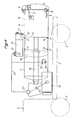
- FIGS. 1 and 2 in which the device according to the invention has been illustrated mounted on the platform 1 of a truck of which the cabin 2 and the wheels 3 have also been shown diagrammatically.
- a cylindrical tubular tank 4 provided at its rear end with a door 5 hinged at 6 at the top, the opening and closing of the door being ensured by jacks 7. It is by elsewhere provided for a rapid locking and unlocking mechanism comprising hooks 8 actuated by jacks 9.
- a fixed wall 10 delimits two compartments, namely a first compartment constituting a tank 11 with clean water for cleaning and the easements and a second compartment constituting an enclosure 12 into which the sludge to be drained must be introduced like this will be explained later.
- a movable partition 13 Inside the enclosure 12 is mounted a movable partition 13, the mounting arrangement of which is illustrated in FIGS. 3 to 5.
- the partition 13 constitutes the bottom wall of a cylindrical shield having two annular belts 14, a central hub 15 and radial reinforcing ribs 16 connecting the two belts 14 and the hub 15.
- the outside diameter of the belts 14 is less to the inside diameter of the wall of the enclosure 12.
- two crowns of brass pads 17 are mounted ensuring the guiding of the shield and therefore of the partition 13 on the inside wall of the enclosure 12.
- Each pads 17 is mounted by a wedge 17 ⁇ automatically adjusting the application of the corresponding pad on the surface of the wall.
- Each wedge 17 ⁇ is made up of a corrugated metal blade. Such adjustment means are useful in view of the deformations of the shield and of the wall of the enclosure which can occur following prolonged operation.
- the pads 17 are arranged so as to extend over 60 to 80% of the inner circumference of the enclosure 12 leaving between them passages for the flow of water separated from the sludge during the displacement of the partition 13.
- the hub 15 is integral, at its end opposite to the partition 13, with the rod of a double-acting cylinder 18, associated with control means, not shown, allowing it to communicate a variable speed and pressure of thrust.
- the speed can vary between 0 and 3 meters / minute and the thrust pressure from 0 to 300 bars.
- the hydraulic pressure can be displayed on a pressure gauge not shown.
- This circuit includes a pump 19 driven from the engine of the truck by a transfer box mounted between the gearbox and the rear axle or by a PTO, or by an auxiliary motor.
- the pump includes an air filter 20 and an exhaust silencer 21.
- the pump is connected through a non-return valve 22 to a four-way valve 23 controlling the reversal of the flow of the pump 19 to set at will in depression and in overpressure the enclosure 12.
- a pipe 24 By a pipe 24 the valve 23 is connected to a safety tank 25 mounted at the upper part of the tank 4, a ball valve 26 of protection being provided.
- the reservoir 25 is further provided with a level probe 27 controlling a vent valve 28 upstream of which is a pressure relief valve 29.
- the reservoir 25 is connected to the enclosure 12 by a pipe 30 leading to the upper part of the enclosure.
- the tubing 30 opens into the enclosure 12 at a location disposed in front of the partition 13 when the latter is in the position of maximum withdrawal corresponding substantially to the position shown in the drawing.
- a level control in the form of a transparent conduit 32 is provided to control the degree of filling and the consistency of the sludge introduced.
- This comprises, first of all, for discharging the water in front of the partition 13 in the withdrawn position, a mouth 33 of a pipe 34 isolable by a valve 35.
- the pump 38 can be driven from the vehicle engine.
- the discharge pipe 39 of the pump 38 on which the pipe 34 also opens comprises a part of transparent pipe 40 intended to control the consistency of the pumped water, and opens into a battery of two filters 41 mounted in parallel, switching between the two filters carried out by isolation valves 42.
- a separate water discharge mouth 43 is provided downstream of the filters 41.
- the filters 41 can be emptied manually by replacing the filtering grids which they contain or, alternatively, a sludge recycling circuit 43 ⁇ can be provided, shown in phantom and opening into the enclosure 12.
- a conduit 44 for evacuation of the residual water being able to be in the enclosure 12 in front of the partition 13, there is provided a conduit 44 making it possible to bring the water back into the zone of the enclosure behind the partition when the latter is in position advanced during its compaction stroke, as will be explained later in relation to operation.
- the device also comprises two pressure gauges 45 and 46 on either side of the partition 13.
- the device also includes a manhole 47 making it possible to visually check the consistency of the dried-up sludge in the vicinity of door 5 as well as a position detector 48 detecting in particular the passage of the partition 13 opposite the tube 30.
- the desired vacuum is created in the enclosure behind the partition 13.
- the jack 18 is actuated so that the displacement of the partition 13 is carried out first at high speed and with a low compaction pressure, then as the sludge in front of the partition 13 dries up at a slower speed and a maximum compaction pressure.
- reciprocating movements of the partition 13 can be carried out associated with flow reversals in the enclosure by maneuvering of valve 23. These operations can be carried out by gradually increasing the actuator pressure.
- pump 38 is used which can operate continuously.
- the non-return valve 37 When the pump 19 is in the suction phase creating a vacuum in the enclosure 12 the non-return valve 37 is closed. When the flow is reversed in the pump 19 or when the latter is disengaged the non-return valve 37 opens and the pump 38 evacuates the settling water towards the filters 41. The residual water in front of the partition 13 is evacuated via line 44 and is reinjected into the enclosure behind the partition 13 when the latter is in the vicinity of its limit switch to the left in FIG. 1. The drying operation will be completed once the pressure read on the pressure gauge 46 will be equal to the pressure displayed by the pressure gauge 45 corresponding to the vacuum produced.
- the door 5 is opened and the jack 18 is actuated, the partition 13 then playing the role of an ejector piston.
Landscapes
- Engineering & Computer Science (AREA)
- Health & Medical Sciences (AREA)
- Life Sciences & Earth Sciences (AREA)
- Hydrology & Water Resources (AREA)
- Public Health (AREA)
- Water Supply & Treatment (AREA)
- Mechanical Engineering (AREA)
- Treatment Of Sludge (AREA)
Applications Claiming Priority (2)
| Application Number | Priority Date | Filing Date | Title |
|---|---|---|---|
| FR8604945A FR2596749B1 (fr) | 1986-04-07 | 1986-04-07 | Procede et dispositif d'assechement de boues |
| FR8604945 | 1986-04-07 |
Publications (1)
| Publication Number | Publication Date |
|---|---|
| EP0241375A1 true EP0241375A1 (de) | 1987-10-14 |
Family
ID=9333972
Family Applications (1)
| Application Number | Title | Priority Date | Filing Date |
|---|---|---|---|
| EP87400776A Withdrawn EP0241375A1 (de) | 1986-04-07 | 1987-04-07 | Verfahren und Vorrichtung zum Entwässern von Schlämmen |
Country Status (2)
| Country | Link |
|---|---|
| EP (1) | EP0241375A1 (de) |
| FR (1) | FR2596749B1 (de) |
Families Citing this family (1)
| Publication number | Priority date | Publication date | Assignee | Title |
|---|---|---|---|---|
| FR2717463B1 (fr) * | 1994-03-18 | 1996-06-07 | Magyar Sa | Dispositif pour la récupération de boues par aspiration. |
Citations (6)
| Publication number | Priority date | Publication date | Assignee | Title |
|---|---|---|---|---|
| NL285265A (de) * | 1900-01-01 | |||
| FR364743A (fr) * | 1906-03-30 | 1906-08-27 | Us Fibre Stopper Company | Machine à former des objets en pulpe de fibre |
| CH167589A (fr) * | 1931-03-31 | 1934-02-28 | Cachin Francois | Presse à fonctionnement continu et automatique. |
| GB695605A (en) * | 1950-08-05 | 1953-08-12 | Johann Hoffmann | Pressure filtering process and apparatus |
| GB1535356A (en) * | 1977-02-04 | 1978-12-13 | Green Son & Waite Ltd W | Presses for compressing liquid containing material into block form |
| FR2411815A1 (fr) * | 1977-12-14 | 1979-07-13 | Hydromer Soc Civ | Procede et dispositif de traitement de dechets tels qu'ordures menageres et amendement organique obtenu suivant ce procede |
-
1986
- 1986-04-07 FR FR8604945A patent/FR2596749B1/fr not_active Expired - Fee Related
-
1987
- 1987-04-07 EP EP87400776A patent/EP0241375A1/de not_active Withdrawn
Patent Citations (6)
| Publication number | Priority date | Publication date | Assignee | Title |
|---|---|---|---|---|
| NL285265A (de) * | 1900-01-01 | |||
| FR364743A (fr) * | 1906-03-30 | 1906-08-27 | Us Fibre Stopper Company | Machine à former des objets en pulpe de fibre |
| CH167589A (fr) * | 1931-03-31 | 1934-02-28 | Cachin Francois | Presse à fonctionnement continu et automatique. |
| GB695605A (en) * | 1950-08-05 | 1953-08-12 | Johann Hoffmann | Pressure filtering process and apparatus |
| GB1535356A (en) * | 1977-02-04 | 1978-12-13 | Green Son & Waite Ltd W | Presses for compressing liquid containing material into block form |
| FR2411815A1 (fr) * | 1977-12-14 | 1979-07-13 | Hydromer Soc Civ | Procede et dispositif de traitement de dechets tels qu'ordures menageres et amendement organique obtenu suivant ce procede |
Also Published As
| Publication number | Publication date |
|---|---|
| FR2596749A1 (fr) | 1987-10-09 |
| FR2596749B1 (fr) | 1991-04-12 |
Similar Documents
| Publication | Publication Date | Title |
|---|---|---|
| FR2706788A1 (de) | ||
| FR2596749A1 (fr) | Procede et dispositif d'assechement de boues | |
| US3707070A (en) | Method of processing weeds | |
| JPH0663599A (ja) | 汚泥・土砂類の脱水乾燥法及びその装置 | |
| FR2685305A1 (fr) | Citerne a cloison interieure mobile. | |
| WO1993006808A1 (fr) | Lit medical fluidise muni d'un dispositif d'evacuation de ses constituants granulaires souilles | |
| FR2928669A1 (fr) | Machine de curage | |
| FR2808496A1 (fr) | Dispositif permettant la recuperation des nappes de fioul flottant a la surface de la mer ou en faible immersion | |
| CA2511876A1 (fr) | Unite mobile de vidange et de pretraitement d'eaux usees issues notamment d'assainissement non collectif, et procede correspondant | |
| JP2021130958A (ja) | 管内清掃方法 | |
| EP1098158B1 (de) | Verwaltungsvorrichtung für in einem Wärmetauscher zirkulierenden Festkörper | |
| FR2632334A1 (fr) | Dispositif de curage, notamment pour le nettoyage d'un egout en service normal | |
| FR2514605A1 (fr) | Installation pour le brassage, l'homogeneisation, et l'epandage de liquides charges | |
| FR2663373A1 (fr) | Procede et dispositif pour etablir une depression dans une zone de terrain permeable isolee de l'atmosphere par une membrane etanche. | |
| FR2693220A1 (fr) | Procédé pour le curage d'ouvrages, notamment d'égouts. | |
| BE1001641A7 (fr) | Vehicule. | |
| FR2749780A1 (fr) | Installation de nettoyage par injection et aspiration avec recyclage separatif | |
| WO1996034678A1 (fr) | Dispositif de mise en pression a actionnement liquide, pour une installation de dessalement d'eau de mer ou d'eaux saumâtres | |
| EP3984816B1 (de) | Tank für saugwagen | |
| CN218283029U (zh) | 一种化工管道安全疏通装置 | |
| BE1013747A3 (fr) | Dispositif pour creer un mouvement dans un liquide. | |
| EP4177479A1 (de) | Unterwasserspeichervorrichtung für druckluft, die von einem hydraulischen rohr erhalten wird | |
| FR2733777A1 (fr) | Dispositif pour le curage des dechets decantes dans les bassins de dessablement d'egouts | |
| EP0433115A1 (de) | Sammelbehälter für Produkte, insbesondere für Haushalts- oder Industriemüll | |
| BE488755A (de) |
Legal Events
| Date | Code | Title | Description |
|---|---|---|---|
| PUAI | Public reference made under article 153(3) epc to a published international application that has entered the european phase |
Free format text: ORIGINAL CODE: 0009012 |
|
| AK | Designated contracting states |
Kind code of ref document: A1 Designated state(s): AT BE CH DE ES GB GR IT LI LU NL SE |
|
| 17P | Request for examination filed |
Effective date: 19880225 |
|
| 17Q | First examination report despatched |
Effective date: 19890713 |
|
| STAA | Information on the status of an ep patent application or granted ep patent |
Free format text: STATUS: THE APPLICATION IS DEEMED TO BE WITHDRAWN |
|
| 18D | Application deemed to be withdrawn |
Effective date: 19900503 |
|
| RIN1 | Information on inventor provided before grant (corrected) |
Inventor name: HUWER, JOSEPH |