EP0241396A1 - Automatischer Treibstangenverschluss mit Doppelaktion - Google Patents
Automatischer Treibstangenverschluss mit Doppelaktion Download PDFInfo
- Publication number
- EP0241396A1 EP0241396A1 EP87440015A EP87440015A EP0241396A1 EP 0241396 A1 EP0241396 A1 EP 0241396A1 EP 87440015 A EP87440015 A EP 87440015A EP 87440015 A EP87440015 A EP 87440015A EP 0241396 A1 EP0241396 A1 EP 0241396A1
- Authority
- EP
- European Patent Office
- Prior art keywords
- cremone bolt
- automatic
- double action
- rods
- bolt according
- Prior art date
- Legal status (The legal status is an assumption and is not a legal conclusion. Google has not performed a legal analysis and makes no representation as to the accuracy of the status listed.)
- Granted
Links
- 230000000694 effects Effects 0.000 claims description 5
- 240000008042 Zea mays Species 0.000 description 3
- 230000006835 compression Effects 0.000 description 1
- 238000007906 compression Methods 0.000 description 1
- 230000006866 deterioration Effects 0.000 description 1
- 230000001737 promoting effect Effects 0.000 description 1
Images

Classifications
-
- E—FIXED CONSTRUCTIONS
- E05—LOCKS; KEYS; WINDOW OR DOOR FITTINGS; SAFES
- E05C—BOLTS OR FASTENING DEVICES FOR WINGS, SPECIALLY FOR DOORS OR WINDOWS
- E05C9/00—Arrangements of simultaneously actuated bolts or other securing devices at well-separated positions on the same wing
- E05C9/04—Arrangements of simultaneously actuated bolts or other securing devices at well-separated positions on the same wing with two sliding bars moved in opposite directions when fastening or unfastening
- E05C9/042—Arrangements of simultaneously actuated bolts or other securing devices at well-separated positions on the same wing with two sliding bars moved in opposite directions when fastening or unfastening with pins engaging slots
-
- Y—GENERAL TAGGING OF NEW TECHNOLOGICAL DEVELOPMENTS; GENERAL TAGGING OF CROSS-SECTIONAL TECHNOLOGIES SPANNING OVER SEVERAL SECTIONS OF THE IPC; TECHNICAL SUBJECTS COVERED BY FORMER USPC CROSS-REFERENCE ART COLLECTIONS [XRACs] AND DIGESTS
- Y10—TECHNICAL SUBJECTS COVERED BY FORMER USPC
- Y10S—TECHNICAL SUBJECTS COVERED BY FORMER USPC CROSS-REFERENCE ART COLLECTIONS [XRACs] AND DIGESTS
- Y10S292/00—Closure fasteners
- Y10S292/62—Lost motion connections
-
- Y—GENERAL TAGGING OF NEW TECHNOLOGICAL DEVELOPMENTS; GENERAL TAGGING OF CROSS-SECTIONAL TECHNOLOGIES SPANNING OVER SEVERAL SECTIONS OF THE IPC; TECHNICAL SUBJECTS COVERED BY FORMER USPC CROSS-REFERENCE ART COLLECTIONS [XRACs] AND DIGESTS
- Y10—TECHNICAL SUBJECTS COVERED BY FORMER USPC
- Y10T—TECHNICAL SUBJECTS COVERED BY FORMER US CLASSIFICATION
- Y10T292/00—Closure fasteners
- Y10T292/08—Bolts
- Y10T292/0801—Multiple
- Y10T292/0834—Sliding
- Y10T292/0836—Operating means
- Y10T292/0837—Cam and lever
-
- Y—GENERAL TAGGING OF NEW TECHNOLOGICAL DEVELOPMENTS; GENERAL TAGGING OF CROSS-SECTIONAL TECHNOLOGIES SPANNING OVER SEVERAL SECTIONS OF THE IPC; TECHNICAL SUBJECTS COVERED BY FORMER USPC CROSS-REFERENCE ART COLLECTIONS [XRACs] AND DIGESTS
- Y10—TECHNICAL SUBJECTS COVERED BY FORMER USPC
- Y10T—TECHNICAL SUBJECTS COVERED BY FORMER US CLASSIFICATION
- Y10T292/00—Closure fasteners
- Y10T292/57—Operators with knobs or handles
Definitions
- the invention relates to a double action automatic cremone bolt comprising two rods held engaged in the locked position in a set of strikes by elastic return elements and being withdrawn in an unlocked position by a set of angular levers articulated at their top.
- these angular levers comprising, at the end of their other branch, a light in which engages a lug at least one control rod exerting its action transverse to the rods and being integral with an operating and control handle returned to the rest position by an elastic effect.
- an automatic double action cremone bolt comprising two rods held engaged in the locking position in a set of strikes by elastic return elements and being withdrawn in an unlocking position by a set of angular levers articulated at their top in the cremone bolt case and each connected, by the end of one of its branches, to one of the rods, these angular levers comprising, at the end of their other branch, a light in which engages a lug of at least one control rod exerting its action transversely to the rods and being secured to an operating and control handle returned to the rest position by an elastic effect.
- this known lever requires a handle in the form of an elongated bar allowing a certain flexion in order to be able to exert a traction on the control rod acting on the angular levers to remove the rods from their keepers.
- the cremone mechanism transmitting to the rods the impulse given to the handle, connects the latter to the rods in a constant manner. Therefore, when closing the opening, the rods are difficult to engage in their. strikes. Indeed, to close the opening, it is necessary to exert a push on the handle. This thrust is transmitted to the rods through the inter the mechanism of the cremone bolt and it opposes any recoil of the rods. However, this retreat is essential to allow the rods to enter their respective strike. Consequently, it is necessary to let go of the handle during the last phase of the closing of the opening and act directly on the latter to cause the retraction of the rods to allow their engagement in the strikes and thus to give the cremone bolt its locking position.
- the object of the present invention is to remedy these drawbacks and to design an automatic cremone bolt capable of equipping either outward opening or inward opening, while allowing easy and secure closing of the opening.
- the invention as characterized in the claims, solves the problem of creating a double action automatic cremone bolt comprising two rods held engaged in the locked position in a set of strikes by elastic return elements and being withdrawn in an unlocking position by a set of angular levers articulated at their apex in the gearbox and each connected, by the end of one of its branches, to one of the rods, these angular levers comprising, at the end their other branch, a light in which engages a lug of at least one control rod exerting its action transversely to the rods and being secured to an operating and control handle returned to the rest position by an elastic effect, this light of the other branch of the angular levers being arranged on the edge of said branch so as to form an open clearance, the bottom of which constitutes a cooperative attack song t, when unlocking
- the action of the lug includes an additional free stroke delimited by the leading edge and one of the side walls of the bortier.
- the invention by this idle stroke, creates the conditions making it possible to provide a design ensuring a certain closure of the opening window compensating for a possible failure of the elastic return means of the rods or that, for a reason any; the force required to introduce the rods into their keepers is greater than that provided by said elastic return means of the rods.
- the automatic lever, object of the present invention is easier to operate and can be used either on the right or on the left after simple reversal, when the operating and control handle is a lever secured to the housing and articulated on a axis parallel to the rods and comprising, opposite the lever arm, the control rod provided with the lug.
- the easier operation of the automatic lever is further accentuated by a measure providing that the operating and control handle comprises two parallel and spaced control rods each acting by its lug on the leading edge of an angular lever disposed on its scope.
- each angular lever comprises a curvature con - cellar promoting sliding of the lug on the driving edge and that each rod comprises at its end connected to the angle lever a slide guided in the hammer and being engaged with the angular lever. by a connecting element engaged in a light.
- each slide comprises, for this purpose, a connecting element with a rod.
- each rod has at its end connected to the angular lever a ramp arranged across the path traveled by the respective lug during the empty stroke of the handle.
- the linkages are always fully pushed into the locking position, even when the opening of the opening leaf or other obstacle prevents the automatic elastic return of the linkages.
- the lugs integral with the operating and control handle, slide along the ramps during the idle stroke of the handle and push the rods into their locked positions.
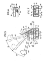
- the double action automatic cremone bolt 1 in accordance with the invention, comprises a boot 2 enclosing a mechanism making it possible to actuate two rods moving in opposite directions and engaging in strikes integral with the frame to ensure the locking of the opening . These 'two rods (not shown) are held engaged in the locked position in said strikes by elastic return elements.
- the mechanism comprises a set of angular levers 3, 4 connected by a link 5, 6 to the rods.
- These angular levers 3, 4 can pivot around an axis 7, 8 secured to the internal face 9 of one of the walls 10 of the shoemaker 2.
- This axis 7, 8 passes through an orifice 11, 12 produced in the apex 13, 14 of said angular levers 3, 4.
- the latter comprise a first branch 15, 16 in which a hole 17, 18 is produced in which a stud 19, 20 can slide.
- this stud 19, 20 is integral with one of the faces 21 of the end of the rods passing through lights made in the edges 22, 23 of the case 2.
- this stud 19, 20 is integral with one of the faces 21 of a slide 24, 25 moving in the box 2 and guided by the side walls 26, 27 of the latter.
- this connecting element 29, 30 passes through a light. oblong 31 made in the other wall 32 of the housing 2.
- This connecting element 29, 30 projects relative to the external face 33 of the wall 32 of the housing 2.
- this connecting element 29, 30 has the form of 'an axis on which is threaded the end of one of the rods. Therefore, it is possible to separate the boot 2 from the rods, which facilitates the storage of the automatic locking rod 1. Furthermore, it is possible to adjust the length of the rods according to the height of the opening.
- the angular levers 3, 4 comprise a second branch 34, 35 also having a light 36, 37.
- this light 36, 37 is arranged on the edge 38, 39 of the second branch 34, 35 so that one obtains an open clearance 40, 41.
- the bottom of this open clearance 40, 41 constitutes a leading edge 42, 43 for means making it possible to actuate said angular levers 3, 4.
- One of these means is a lug 44 disposed at the end 45 of at least one control rod 46 exerting its action transversely to the rods.
- This end 46 provided with the lug 44 moves in a slot 47 produced in the wall 10 of the housing 2.
- this lug 44 exerts a push on the leading edge 42, 43 of the open clearance 40, 41 of the second branch 34, 35 of the angular levers 3, 4.
- the leading edge 42, 43 has a concave curvature 48, 49.
- the control rod 46 is integral with a 5-0 end of an operating and control handle 51.
- This operating and control handle 51 can pivot around an axis 52 held by a yoke 53 secured to the face external 54 of the wall 10 of the boftier 2.
- a yoke 53 secured to the face external 54 of the wall 10 of the boftier 2.
- Said handle maneuvering and control 51 is returned to the rest position by an elastic element 55.
- the latter may be a spring wound on the axis 52 of which one of the branches 56 is fixed and the other branch 57 of which bears against the edge 58 com rod request 46.
- the control rod 46 comprises a positioning pawl 59 sliding in a hub 60 and returned to the action position by an elastic element 61.
- the positioning pawl 59 can occupy three positions 62, 63, 64 , one 62 corresponding to the position 65 of the operating and control handle 51 pushed fully to the opening of the opening, the other 64 corresponding to the rest position 66 of the operating and control handle , 51 and, in the intermediate position 63, the positioning pawl 59 retains the operating and control handle 51 in the intermediate position 67 for closing the opening.
- the operating and control handle 51 comprises two parallel and spaced control rods 46, each acting by its lug 44 on the leading edge 42, 43 of an angular lever 3, 4 disposed in its field of action .
- the automatic lever 1 is in the locked position.
- the lug 44 of the control rod 46 bears against the internal face of the side wall 27 of the housing 2, the operating and control handle 51 is in position 66 while the positioning pawl 59 is in 64 (see Figures 1 and 5).
- the operating and control handle 51 is actuated to put it in the intermediate position 67.
- This operating and control handle 51 travels through an idle stroke 68 corresponding to an idle stroke 69 effected by the pins 44 which are placed against the leading edges 42, 43 of the angular levers 3, 4 (see Figures 2 and 5).
- the lugs 44 actuated by the latter, exert a push on the leading edges 42, 43 by causing the rotation of the angular levers 3, 4 and the compression of the element elastic 55.
- the operating and control handle 51 occupies position 65 and the positioning pawl 59 position 62 (see FIGS. 3 and 5).
- each slider 24, 25 with a ramp 73, 74 projecting relative to the face 21 of these sliders 24, 25.
- This ramp 73 , 74 is arranged across the path traveled by the respective lug 44 during the idle stroke of the operating and control handle 51.
Landscapes
- Engineering & Computer Science (AREA)
- Mechanical Engineering (AREA)
- Closing And Opening Devices For Wings, And Checks For Wings (AREA)
- Mechanical Control Devices (AREA)
- Eye Examination Apparatus (AREA)
- Power-Operated Mechanisms For Wings (AREA)
- Supports Or Holders For Household Use (AREA)
- Blinds (AREA)
Priority Applications (1)
| Application Number | Priority Date | Filing Date | Title |
|---|---|---|---|
| AT87440015T ATE43395T1 (de) | 1986-04-10 | 1987-03-20 | Automatischer treibstangenverschluss mit doppelaktion. |
Applications Claiming Priority (2)
| Application Number | Priority Date | Filing Date | Title |
|---|---|---|---|
| FR8605252 | 1986-04-10 | ||
| FR8605252A FR2597147B1 (fr) | 1986-04-10 | 1986-04-10 | Cremone automatique a double action |
Publications (2)
| Publication Number | Publication Date |
|---|---|
| EP0241396A1 true EP0241396A1 (de) | 1987-10-14 |
| EP0241396B1 EP0241396B1 (de) | 1989-05-24 |
Family
ID=9334177
Family Applications (1)
| Application Number | Title | Priority Date | Filing Date |
|---|---|---|---|
| EP87440015A Expired EP0241396B1 (de) | 1986-04-10 | 1987-03-20 | Automatischer Treibstangenverschluss mit Doppelaktion |
Country Status (9)
| Country | Link |
|---|---|
| US (1) | US4836588A (de) |
| EP (1) | EP0241396B1 (de) |
| JP (1) | JPS62242084A (de) |
| AT (1) | ATE43395T1 (de) |
| CA (1) | CA1298592C (de) |
| DE (1) | DE3760182D1 (de) |
| ES (1) | ES2008874B3 (de) |
| FR (1) | FR2597147B1 (de) |
| GR (1) | GR3000064T3 (de) |
Cited By (1)
| Publication number | Priority date | Publication date | Assignee | Title |
|---|---|---|---|---|
| GB2298449A (en) * | 1995-03-03 | 1996-09-04 | Securistyle Ltd | Multiple bolt locking assembly |
Families Citing this family (3)
| Publication number | Priority date | Publication date | Assignee | Title |
|---|---|---|---|---|
| FR2756863B1 (fr) * | 1996-12-06 | 1999-01-22 | Ferco Int Usine Ferrures | Dispositif de securite de type antifausse manoeuvre pour une ferrure de verrouillage d'un vantail |
| GB0029064D0 (en) * | 2000-11-29 | 2001-01-10 | Meritor Light Vehicle Sys Ltd | Lock arrangement |
| JP2005132272A (ja) * | 2003-10-31 | 2005-05-26 | Hino Motors Ltd | バッテリカバーの押え構造 |
Citations (2)
| Publication number | Priority date | Publication date | Assignee | Title |
|---|---|---|---|---|
| DE2154320A1 (de) * | 1970-11-03 | 1972-05-04 | Grino Gine, Antonio, Barcelona (Spanien) | Schloßvorrichtung für Türen, Fenster und dergleichen |
| DE2730407A1 (de) * | 1977-07-06 | 1979-01-18 | Rasmussen Holding As V Kann | Fenster mit riegeln zum festhalten des fluegelrahmens in der schliesstellung |
Family Cites Families (25)
| Publication number | Priority date | Publication date | Assignee | Title |
|---|---|---|---|---|
| US122061A (en) * | 1871-12-19 | Improvement in latches for gates | ||
| US512022A (en) * | 1894-01-02 | Eben n | ||
| US406903A (en) * | 1889-07-16 | hebert | ||
| DE594187C (de) * | 1934-03-13 | Schloss Und Metallwarenfabrik | Treibriegelverschluss mit entgegengesetzt bewegten Verschlussstangen | |
| US620468A (en) * | 1899-02-28 | Window-fastener | ||
| US543679A (en) * | 1895-07-30 | Joseph dennis | ||
| US844448A (en) * | 1906-09-05 | 1907-02-19 | Leonard B Gaylor | Permutation-lock. |
| US893072A (en) * | 1907-03-22 | 1908-07-14 | George Hayes | Transom-fastener. |
| US908361A (en) * | 1907-12-16 | 1908-12-29 | Reynolds W Vredenburgh | Combined lock and latch. |
| US1174652A (en) * | 1912-10-23 | 1916-03-07 | Edmund H Banks | Automatic twin door-latch. |
| US1354646A (en) * | 1919-11-29 | 1920-10-05 | Earle Hardware Mfg Company | Surface bolt |
| US1493872A (en) * | 1922-07-01 | 1924-05-13 | Briney Charles Eugene | Window-screen latch |
| US1908980A (en) * | 1930-11-26 | 1933-05-16 | Kemp Lock Inc | Lock |
| US2423352A (en) * | 1944-03-27 | 1947-07-01 | Wagner E R Mfg Co | Latch |
| US2502607A (en) * | 1945-12-13 | 1950-04-04 | Manitowoc Shipbuilding Company | Latch |
| CH279219A (de) * | 1949-12-31 | 1951-11-30 | Abel Wilhelm | Schliessvorrichtung an Fenster oder Türe. |
| US2888288A (en) * | 1955-12-21 | 1959-05-26 | Agrafes Francaises & D Article | Locking device |
| US3498657A (en) * | 1966-06-14 | 1970-03-03 | Valextra Spa | Latch means |
| US3904229A (en) * | 1974-05-23 | 1975-09-09 | Ideal Security Hardware Co | Sliding door lock |
| US3953061A (en) * | 1974-09-23 | 1976-04-27 | A. L. Hansen Mfg. Co. | Door fastening means |
| DE2633188A1 (de) * | 1976-07-23 | 1978-01-26 | Goetz Metallbau Gmbh | Betaetigungsgriffbeschlag |
| US4306432A (en) * | 1980-03-25 | 1981-12-22 | Eliezer Ravid | Door lock |
| GB2148377B (en) * | 1983-10-22 | 1987-02-18 | Hardware & Systems Patents Ltd | Improvements in fasteners for doors, windows and the like |
| DE8333991U1 (de) * | 1983-11-26 | 1984-03-22 | Wilh. Engstfeld Gmbh U. Co Kg, 5628 Heiligenhaus | Griffbeschlag fuer treibstangenbeschlaege von fenstern, tueren od. dgl. |
| US4648638A (en) * | 1985-06-24 | 1987-03-10 | Mcknight Roy S | Sliding door lock assembly |
-
1986
- 1986-04-10 FR FR8605252A patent/FR2597147B1/fr not_active Expired
-
1987
- 1987-03-16 US US07/026,388 patent/US4836588A/en not_active Expired - Fee Related
- 1987-03-20 EP EP87440015A patent/EP0241396B1/de not_active Expired
- 1987-03-20 ES ES87440015T patent/ES2008874B3/es not_active Expired
- 1987-03-20 DE DE8787440015T patent/DE3760182D1/de not_active Expired
- 1987-03-20 AT AT87440015T patent/ATE43395T1/de active
- 1987-04-08 CA CA000534160A patent/CA1298592C/fr not_active Expired - Lifetime
- 1987-04-09 JP JP62085882A patent/JPS62242084A/ja active Pending
-
1989
- 1989-05-25 GR GR89400058T patent/GR3000064T3/el unknown
Patent Citations (2)
| Publication number | Priority date | Publication date | Assignee | Title |
|---|---|---|---|---|
| DE2154320A1 (de) * | 1970-11-03 | 1972-05-04 | Grino Gine, Antonio, Barcelona (Spanien) | Schloßvorrichtung für Türen, Fenster und dergleichen |
| DE2730407A1 (de) * | 1977-07-06 | 1979-01-18 | Rasmussen Holding As V Kann | Fenster mit riegeln zum festhalten des fluegelrahmens in der schliesstellung |
Cited By (2)
| Publication number | Priority date | Publication date | Assignee | Title |
|---|---|---|---|---|
| GB2298449A (en) * | 1995-03-03 | 1996-09-04 | Securistyle Ltd | Multiple bolt locking assembly |
| GB2298449B (en) * | 1995-03-03 | 1998-09-16 | Securistyle Ltd | A vent locking assembly |
Also Published As
| Publication number | Publication date |
|---|---|
| FR2597147A1 (fr) | 1987-10-16 |
| JPS62242084A (ja) | 1987-10-22 |
| FR2597147B1 (fr) | 1988-06-10 |
| GR3000064T3 (en) | 1990-10-31 |
| EP0241396B1 (de) | 1989-05-24 |
| CA1298592C (fr) | 1992-04-07 |
| ATE43395T1 (de) | 1989-06-15 |
| ES2008874B3 (es) | 1989-08-16 |
| US4836588A (en) | 1989-06-06 |
| DE3760182D1 (en) | 1989-06-29 |
Similar Documents
| Publication | Publication Date | Title |
|---|---|---|
| EP2179117B1 (de) | Sperrvorrichtung | |
| EP0341173B1 (de) | Treibstangenverschluss für Türen, Fenster o.dgl. | |
| FR2555643A1 (fr) | Dispositif d'ouverture et de fermeture electrique d'un battant de vehicule muni d'une serrure du type a armement | |
| EP0246172B1 (de) | Verriegelungsvorrichtung, insbesondere für Schiebefenster | |
| EP0207869B1 (de) | Einlassespagnolette mit zwei Treibstangen und Zentralriegel | |
| WO1993006324A1 (fr) | Serrure d'une armoire d'appareillage electrique | |
| EP0869239A1 (de) | Verriegelungsbeschlag für Schiebetür, Schiebefenster oder ähnliches | |
| EP0241396B1 (de) | Automatischer Treibstangenverschluss mit Doppelaktion | |
| EP0262067B1 (de) | Verriegelungsvorrichtung, insbesondere für Schiebeflügel | |
| EP1030017B1 (de) | Treibstangenschloss enthaltend einen Hakenriegel mit Mitteln zur Riegelblockierung | |
| EP2078810B1 (de) | Reversible, modulare mehrzweckpanikverschlussvorrichtung | |
| EP0220127B1 (de) | Verriegelungseinrichtung für Schiebeflügel | |
| EP1030015B1 (de) | Verriegelungsbeschlag des Typs mit Treibstangen oder ähnlichem | |
| EP2045420A1 (de) | Griffsystem, insbesondere Treibstange, das zur Befestigung auf der Außenseite einer Tür bestimmt ist, wie etwa der Tür eines Kühllasters | |
| EP0404609A1 (de) | Türschloss und -beschlag für Panikfälle | |
| FR2861789A1 (fr) | Serrure anti-panique multipoint reversible | |
| EP0070576B1 (de) | Treibstangengetriebe für Tür, Fenster o.dgl. | |
| EP0331595B1 (de) | Beschlag für eine zweiteilige Tür | |
| FR2680825A1 (fr) | Ferrure de verrouillage pour porte, fenetre ou analogue. | |
| EP1718827B1 (de) | Antipanikstange und damit ausgerüstete tür | |
| EP0237421B1 (de) | Verschluss, insbesondere für Kühlkammertür | |
| EP0410886A1 (de) | Drehgriff mit Entriegelungsdruckknopf | |
| FR2571086A1 (fr) | Ferrure de verrouillage notamment pour ouvrant coulissant. | |
| FR2610034A3 (fr) | Dispositif de verrouillage d'un ouvrant par tringle coulissante adaptable a un verrou targette monobloc | |
| FR2781003A1 (fr) | Ensemble de fermeture d'urgence pour porte commande par une plaque de poussee formant poussoir |
Legal Events
| Date | Code | Title | Description |
|---|---|---|---|
| PUAI | Public reference made under article 153(3) epc to a published international application that has entered the european phase |
Free format text: ORIGINAL CODE: 0009012 |
|
| AK | Designated contracting states |
Kind code of ref document: A1 Designated state(s): AT BE CH DE ES GB GR IT LI NL SE |
|
| 17P | Request for examination filed |
Effective date: 19871126 |
|
| 17Q | First examination report despatched |
Effective date: 19880630 |
|
| GRAA | (expected) grant |
Free format text: ORIGINAL CODE: 0009210 |
|
| AK | Designated contracting states |
Kind code of ref document: B1 Designated state(s): AT BE CH DE ES GB GR IT LI NL SE |
|
| REF | Corresponds to: |
Ref document number: 43395 Country of ref document: AT Date of ref document: 19890615 Kind code of ref document: T |
|
| ITF | It: translation for a ep patent filed | ||
| GBT | Gb: translation of ep patent filed (gb section 77(6)(a)/1977) | ||
| REF | Corresponds to: |
Ref document number: 3760182 Country of ref document: DE Date of ref document: 19890629 |
|
| PLBE | No opposition filed within time limit |
Free format text: ORIGINAL CODE: 0009261 |
|
| STAA | Information on the status of an ep patent application or granted ep patent |
Free format text: STATUS: NO OPPOSITION FILED WITHIN TIME LIMIT |
|
| REG | Reference to a national code |
Ref country code: GR Ref legal event code: FG4A Free format text: 3000064 |
|
| 26N | No opposition filed | ||
| ITTA | It: last paid annual fee | ||
| PGFP | Annual fee paid to national office [announced via postgrant information from national office to epo] |
Ref country code: AT Payment date: 19920310 Year of fee payment: 6 |
|
| PGFP | Annual fee paid to national office [announced via postgrant information from national office to epo] |
Ref country code: GB Payment date: 19920311 Year of fee payment: 6 |
|
| PGFP | Annual fee paid to national office [announced via postgrant information from national office to epo] |
Ref country code: ES Payment date: 19920317 Year of fee payment: 6 |
|
| PGFP | Annual fee paid to national office [announced via postgrant information from national office to epo] |
Ref country code: SE Payment date: 19920319 Year of fee payment: 6 |
|
| PGFP | Annual fee paid to national office [announced via postgrant information from national office to epo] |
Ref country code: CH Payment date: 19920326 Year of fee payment: 6 |
|
| PGFP | Annual fee paid to national office [announced via postgrant information from national office to epo] |
Ref country code: GR Payment date: 19920327 Year of fee payment: 6 |
|
| PGFP | Annual fee paid to national office [announced via postgrant information from national office to epo] |
Ref country code: NL Payment date: 19920331 Year of fee payment: 6 |
|
| PGFP | Annual fee paid to national office [announced via postgrant information from national office to epo] |
Ref country code: BE Payment date: 19920512 Year of fee payment: 6 |
|
| PG25 | Lapsed in a contracting state [announced via postgrant information from national office to epo] |
Ref country code: GB Effective date: 19930320 Ref country code: AT Effective date: 19930320 |
|
| PG25 | Lapsed in a contracting state [announced via postgrant information from national office to epo] |
Ref country code: SE Effective date: 19930321 |
|
| PG25 | Lapsed in a contracting state [announced via postgrant information from national office to epo] |
Ref country code: ES Free format text: LAPSE BECAUSE OF NON-PAYMENT OF DUE FEES Effective date: 19930322 |
|
| PG25 | Lapsed in a contracting state [announced via postgrant information from national office to epo] |
Ref country code: LI Effective date: 19930331 Ref country code: CH Effective date: 19930331 Ref country code: BE Effective date: 19930331 |
|
| BERE | Be: lapsed |
Owner name: FERCO INTERNATIONAL USINE DE FERRURES DE BATIMENT Effective date: 19930331 |
|
| PG25 | Lapsed in a contracting state [announced via postgrant information from national office to epo] |
Ref country code: GR Free format text: THE PATENT HAS BEEN ANNULLED BY A DECISION OF A NATIONAL AUTHORITY Effective date: 19930930 |
|
| PG25 | Lapsed in a contracting state [announced via postgrant information from national office to epo] |
Ref country code: NL Effective date: 19931001 |
|
| NLV4 | Nl: lapsed or anulled due to non-payment of the annual fee | ||
| GBPC | Gb: european patent ceased through non-payment of renewal fee |
Effective date: 19930320 |
|
| REG | Reference to a national code |
Ref country code: CH Ref legal event code: PL |
|
| REG | Reference to a national code |
Ref country code: GR Ref legal event code: MM2A Free format text: 3000064 |
|
| EUG | Se: european patent has lapsed |
Ref document number: 87440015.3 Effective date: 19931008 |
|
| REG | Reference to a national code |
Ref country code: ES Ref legal event code: FD2A Effective date: 19990405 |
|
| PGFP | Annual fee paid to national office [announced via postgrant information from national office to epo] |
Ref country code: DE Payment date: 20000522 Year of fee payment: 14 |
|
| PG25 | Lapsed in a contracting state [announced via postgrant information from national office to epo] |
Ref country code: DE Free format text: LAPSE BECAUSE OF NON-PAYMENT OF DUE FEES Effective date: 20020101 |
|
| PG25 | Lapsed in a contracting state [announced via postgrant information from national office to epo] |
Ref country code: IT Free format text: LAPSE BECAUSE OF NON-PAYMENT OF DUE FEES;WARNING: LAPSES OF ITALIAN PATENTS WITH EFFECTIVE DATE BEFORE 2007 MAY HAVE OCCURRED AT ANY TIME BEFORE 2007. THE CORRECT EFFECTIVE DATE MAY BE DIFFERENT FROM THE ONE RECORDED. Effective date: 20050320 |