EP0241882A1 - Verfahren und Einrichtungen zur Zudosierung von gelösten Stoffen zu Behandlungsbädern - Google Patents
Verfahren und Einrichtungen zur Zudosierung von gelösten Stoffen zu Behandlungsbädern Download PDFInfo
- Publication number
- EP0241882A1 EP0241882A1 EP87105365A EP87105365A EP0241882A1 EP 0241882 A1 EP0241882 A1 EP 0241882A1 EP 87105365 A EP87105365 A EP 87105365A EP 87105365 A EP87105365 A EP 87105365A EP 0241882 A1 EP0241882 A1 EP 0241882A1
- Authority
- EP
- European Patent Office
- Prior art keywords
- container
- containers
- substance
- dosing
- valve
- Prior art date
- Legal status (The legal status is an assumption and is not a legal conclusion. Google has not performed a legal analysis and makes no representation as to the accuracy of the status listed.)
- Withdrawn
Links
Images






Classifications
-
- D—TEXTILES; PAPER
- D06—TREATMENT OF TEXTILES OR THE LIKE; LAUNDERING; FLEXIBLE MATERIALS NOT OTHERWISE PROVIDED FOR
- D06B—TREATING TEXTILE MATERIALS USING LIQUIDS, GASES OR VAPOURS
- D06B23/00—Component parts, details, or accessories of apparatus or machines, specially adapted for the treating of textile materials, not restricted to a particular kind of apparatus, provided for in groups D06B1/00 - D06B21/00
- D06B23/20—Arrangements of apparatus for treating processing-liquids, -gases or -vapours, e.g. purification, filtration or distillation
- D06B23/205—Arrangements of apparatus for treating processing-liquids, -gases or -vapours, e.g. purification, filtration or distillation for adding or mixing constituents of the treating material
-
- B—PERFORMING OPERATIONS; TRANSPORTING
- B01—PHYSICAL OR CHEMICAL PROCESSES OR APPARATUS IN GENERAL
- B01J—CHEMICAL OR PHYSICAL PROCESSES, e.g. CATALYSIS OR COLLOID CHEMISTRY; THEIR RELEVANT APPARATUS
- B01J4/00—Feed or outlet devices; Feed or outlet control devices
- B01J4/008—Feed or outlet control devices
Definitions
- the invention relates to a method for metering dissolved substances into treatment baths, for example washing and / or finishing baths in the textile industry, and to devices for carrying out this method.
- dissolved substances In process engineering, for example in the textile industry, preferably in textile dyeing with reactive dyes or acid dyes, dissolved substances have to be added to the treatment baths during the course of the process in order to change the condition variables of the treatment bath as a function of time. Depending on the process and treatment bath, the dissolved substances are then added linearly, progressively or degressively per unit of time.
- the dye-fiber reaction In order to obtain good quality goods during this dyeing, for example, the dye-fiber reaction must have reached the final fixation within the specified dyeing time. So that this can actually happen, the same pH value must exist at all points in the dye bath and dyeing unit and experience the same change. The pH must also trigger such a fixing rate that sufficient migration ability remains even during the reaction so that the fixed dye can be replaced evenly from the liquor.
- the dye-fiber reaction rate depends first of all on the concentration of reactive dye on the fiber, on the pH and on the temperature. Because of the salt, the concentration of reactive dye on the fiber is high at the start of the reaction.
- the reaction rate is higher at the beginning than at the end of the reaction.
- the high initial speed at the start of the alkali is shown in the conventional staining method in the steep increase in the fixation curve when soda is added.
- the alkali is dosed now in such a way that the pH in the entire unit or in the treatment bath rises evenly and according to an optimized curve, so that the fixation yield under the given temperature conditions does not exceed a system-related percentage per minute.
- the desired linear pH curve corresponds to a progressive alkali metering.
- process-controlled metering pumps have already been developed in order to supply the dye bath with a solution of a given, constant concentration per unit of time (e.g. sodium hydroxide solution) in different quantities, the control system being designed in such a way that these solution quantities per unit of time depending on the need and application dosed progressively, degressively or linearly.
- the solution quantities have a constant concentration.
- alkali is added to the dye bath to fix the dye to the fibers. If the required alkali were contained in the dyebath from the start, it would very likely only be possible to achieve a very uneven staining with reactive dyes currently in use. It is therefore common today in many processes to add the alkali in portions. It is often recommended to start with the first serving with a weakly alkaline agent (e.g. soda) and only to use a strongly alkaline agent (e.g. NaOH) from one of the subsequent servings. For dyes, which absorb neutral to moderate to the fiber, but pull very strongly under the action of fixative alkali, a careful increase in the alkali concentration is extremely advantageous for uniformity and reproducibility of the dyeing.
- a weakly alkaline agent e.g. soda
- a strongly alkaline agent e.g. NaOH
- a device for a progressive addition of alkali is described in EP 0 126 042 / A2.
- This is connected to a dyeing machine for textile goods and essentially consists of a controlled pump, which feeds the dyeing machine with lye.
- the pump is controlled by a control unit, which contains a microprocessor.
- the invention is therefore based on the object of proposing a method with which the same purpose can be achieved, but relatively simple mechanical means can be used to carry out the method.
- the method according to the invention is now characterized in that approximately equal volumes of solution with different substance concentrations are added to the bath in the same time units during the course of the method.
- This method can be carried out with very simple devices, a first device of this type being characterized by at least two containers of substantially the same height, which are connected to one another via an overflow and lifting tube, and one of the containers by at least one outlet opening that can be shut off by a valve owns and a mixing device is provided in this container.
- the same method can also be carried out with a further device, which is characterized by at least two containers and one container has at least one outlet opening near the bottom that can be shut off by a valve, and in this container a mixing device is provided and the second container is arranged above the first container with a Outflow opening close to the ground, which can be shut off by means of a valve, with an outflow pipe projecting into the first container and the above-lying container being airtight.
- a further device which is characterized by at least two containers and one container has at least one outlet opening near the bottom that can be shut off by a valve, and in this container a mixing device is provided and the second container is arranged above the first container with a Outflow opening close to the ground, which can be shut off by means of a valve, with an outflow pipe projecting into the first container and the above-lying container being airtight.
- FIGS. 1a to 1d various possible arrangements of basic elements of an inventive device are shown in a schematic manner.
- a device according to the invention consists of containers B1 ... B3, which are connected to one another in a chain.
- a reaction vessel for the medium into which the substance to be dosed is to be added is shown in FIGS. 1a to 1d.
- the containers B1 ... B3 can be arranged one above the other (Fig.1a.1b), next to each other (1c), one inside the other (Fig.1d) or in some other way. It also does not matter whether the containers B1 ... B3 are directly through openings contained in partitions (Fig.1a). are connected to each other via pipes (Fig.1b.1c) or in some other way.
- at least two containers are required, as will be explained later.
- FIG. 2a shows an arrangement of the containers B1... B3 corresponding to FIG. 1a in somewhat more detail.
- a container B1 is connected to a container B2 via an opening O1, and this is connected to a container B3 via an opening O2.
- the container B1 has inlet openings V1 at the top and an inlet valve V2 in the vicinity of the container base.
- At or in the bottom of the container B3 there is an inlet valve V3 and an outlet valve V4.
- the latter leads to a reaction vessel, not shown in this figure.
- a stirring element M fastened to a common axis a, which ensures thorough mixing of the container contents.
- the axis of these stirring elements M is not only rotatable but also longitudinally displaceable.
- a closure cover D fastened to it can be slipped liquid-tight over the opening O1 provided between the containers B1 and B2.
- Such a cover is not necessary in every case, but useful if the dosing substance remains in the device for a longer period of time before use.
- valves V2 and V3 are opened.
- the valve V4 is closed.
- Evaporating liquid for example water
- the valve V3 is closed - for example by hand or electromagnetically.
- aqueous alkali - is filled through the opening V1 into the container B1. If necessary, the dosing substance can be diluted with a dilution liquid.
- valve V1 or another opening must remain open as an air inlet.
- a circulation pump is often provided for better mixing of the medium to which the dosing substance is to be added hen.
- the dosing substance flowing out of the valve V4 is preferably fed directly into the circulating pump, so that it is distributed well and quickly in the medium.
- the closure cover D is provided, by means of which the opening O1 can be closed.
- FIG. 2b An alternative solution is shown in Fig. 2b.
- the axis of rotation A for the stirring elements M is mounted in the container intermediate walls on liquid-tight bearings.
- the liquid conveyance between the containers B1 ... B3 takes place via transfer lines U1 and U2, the transfer line U1 between the containers B1 and B2 being controllable via a valve V5.
- a valve thus flows through the valve V4, which over time has an increasingly higher concentration C (t) of substance to be metered.
- the container B1 contains the substance to be dosed and the containers B2 and B3 are used as mixing containers. They are filled with the diluent.
- the minimum configuration would be a device with only two containers serving for dosing into question by using only one mixing container instead of two mixing containers B2 and B3.
- such a minimal configuration should serve as a starting point for the calculation of the concentration curve C2 (t), ie the concentration of the dosing substance in the last mixing container and thus at the same time the concentration of the dosing substance that leaves the last container at time t. This can be calculated as follows:
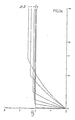
- the concentration curve c2 (t) shows the alkali concentration supplied per unit of time and depends on the amount of alkali used (not varied in Fig. 3) and on the volume ratio of the containers B1 and B2. Please note that - as soon as container B1 is empty - the concentration in container B2 As a result, the alkali is metered linearly from this point in time. If the container volume V 1 is chosen to be very small, a linear dosing process will consequently occur very quickly. If the addition of alkali in the first phase is to be as slow as possible, but then progressively increasing, the container volumes V20 / V10 should be selected between 1: 2 and 1: 1.
- V20: V10 are between 1: 2 and 1: 1.
- the concentration can be varied within an extremely wide range. This has a very advantageous effect, particularly in the case of Faeberbaeders.
- the concentration of the metered substance never changed. If the metering substance is to be added in particularly small amounts, it is only added dropwise, ie batchwise. But with highly effective agents (e.g. fixing alkali) even a drop can be too much if it enters the dye bath in a highly concentrated form. For this reason, the substances to be dosed in dye baths are usually provided in diluted form and added until the end in this dilution.
- the device according to the invention can be used not only for a progressive dosage but also for a degressive one Dosage can be used.
- the container or containers with the dilution medium are simply connected upstream of the container or containers with the dosing substance.
- the device can of course also be used for linear metering.
- all dosing and mixing containers contain a liquid with the same chemical composition.
- Containers, stirrers, valves can be made of stainless steel or, depending on the specific requirements, of other materials. The choice of materials is no problem for the expert.
- the stirrer or stirrers ensure thorough mixing in the containers. Variations are in the arrangement of valves and taps, which allow different loading of the container.
- the device according to the invention is suitable for dosing, inter alia - Alkaline compounds, in particular alkali metal or alkaline earth metal hydroxides or alkali metal salts, for example sodium or potassium hydroxide or calcium hydroxide, sodium or potassium carbonate or sodium or potassium hydrogen carbonate or sodium or potassium phosphate, furthermore ammonium hydroxide or organic C1-C4 alkyl or alkanolamines (e.g.
- Diaethyl or diaethanolamine or mixtures of such compounds;
- - Acids especially inorganic mineral acids such as hydrochloric, sulfuric or phosphoric acid, also organic acids, such as low molecular weight mono-, di- or tricarboxylic acids (formic acid, acetic acid, oxalic acid, citric acid etc.); or acid mixtures;
- - Salts for example neutral acidic or alkaline salts, such as sodium chloride, sodium sulfate, alkali metal hydrogen phosphates, sodium acetate, ammonium sulfate and also mixtures of such salts;
- - Dyes or dye mixtures which are suitable for a wide variety of substrates, for example textile dyes which are characterized as direct, acidic, reactive, disperse or basic dyes (For details, see Color Index, published by the Society of Dyers and Colorists);
- - Aids such as those required in dyeing or finishing or other treatment baths for textiles, paper, leather, plastic
- the chemical compounds to be dosed are generally dosed as aqueous or water-containing liquid preparations. It is also possible to dose various of the compounds mentioned in succession or together (e.g. salts and alkaline compounds).
- Another possible application concerns e.g. the control of crystallization processes in the production of (pure) (crystallized) chemical compounds.
- the dosing substance is not used here during a dosing process released in constant concentration, but mixed with a varying proportion of diluent. If in the medium - as is especially the case with dye baths - there are already large amounts of the liquid used as a diluent, this does not matter in most cases. This is the case, for example, when dyeing natural or synthetic nitrogen-containing fiber materials (wool, polyamide) and cellulosic fiber materials or fiber mixtures containing them with reactive dyes.
- the aqueous alkali metal hydroxide solution is dosed into the aqueous dye bath. The additional diluent added during the dosing process is negligible.
- a great advantage of the invention is that the metering liquid can flow out linearly, so that there is no need for complex pump control.
- Another great advantage of the invention is that, owing to the concentration variation in the metered liquid added, less diluent is required overall than with conventional metering.
- Dyeing unit reel runner Dyestuff: 200kg pure cotton yarn Color bath: 3,000 lt Salt: 50g / lt solid sodium chloride Dye: 8kg (4% of the fiber weight) (CI Reactiv Black 5) Alkali: 2.5 ml / lt sodium hydroxide 36 ° Bé Color temperature: 40 ° C
- Container 1 7.5 lt sodium hydroxide 36 ° Bé; Container filled with water (to 30 lt) Containers 2 and 3: 30 lt of water each Expiry time: 60 minutes (or pump output: 1.5 lt / min).
- the textile material is retracted at room temperature.
- the dye bath is then set to 40 ° C.
- the pre-dissolved dye and then the salt are added in solid form.
- the containers B2 and B3 are filled with water.
- the container B1 with sodium hydroxide 36 ° Bé and water provided.
- the pump of the dosing device is started and the entire contents of the dosing container are evenly let into the dye bath.
- dyeing is carried out at 40 ° C. without further additions.
- the usual measures for the removal of hydroxylated / unfixed dye are taken.
- Dyeing equipment circulation apparatus Color: 700g polyamide 6 flake Fleet ratio: 1:15 Salt: 1g / lt sodium acetate Leveling agent: 1% of the fiber weight of non-ionic auxiliary Dye: 1.5% of the fiber weight of a commercial dye (CI Acid Orange 162) and 1.3% of the fiber weight of a commercial dye (CI Acid Brown 298)
- Container 1 21g acetic acid 80%, container filled with water (to 50 ml)
- Containers 2 and 3 50 ml of water each Expiry time: 50 minutes (or pump output: 3ml / min)
- FIGS. 7, 8 and 9 illustrate a further diagram and further devices for carrying out the method.
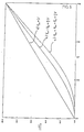
- the diagram according to FIG. 7 illustrates the course of a linear, ideal pH curve when dyeing cellulose fibers with reactive dyes.
- this is a first section of the fixing time, in order to obtain quality goods, u. a. the pH value of the dye liquor increases linearly. Since the pH value corresponds to the negative decadal loar rhythm of the hydrogen ion concentration, it can be seen that the alkali dosage per unit of time must be progressive in order to achieve the linear course of the pH curve.
- This illustrates the upper curve line 1 drawn in during the time T 1 - T 2, which indicates the volume-related amount of the sodium barrel added per unit of time. With increasing fixation time, the added volume-related amount (Grmm per liter g / l) increases.
- curve line 1 is linear or also degressive.
- curve lines illustrate the dashed lines 1 and 3 in the diagram of FIG. 7.
- Two containers 4 and 5 which correspond essentially to one another with regard to the dimensional relationships (ratio between cross-sectional area and height) and the frame volume, have a common partition 6 and inclined floors 7 and 8, the latter lying in common seed level.
- the first container 4 has a discharge opening 9 near the bottom with a downward-directed discharge pipe 10 and a shut-off valve 11.
- the two containers 4 and 5 are also communicatively connected to one another via an overflow or lifting pipe, the orifices 13 and 14 of this lifting pipe 12 also being in Lie close to the ground.
- This siphon or overflow pipe 12 extends approximately to half the fill level of the containers 4, 5.
- a vertically standing pipe 15 is arranged, which is fastened to the bottom 7 of the container and which has a plurality of openings or openings 16 in the region near the bottom.
- the height of this pipe 15 corresponds approximately to the height of the overflow pipe 12.
- An air supply line 17 protrudes into this tube 15, through which air is let in when the device is in operational use (arrow 18).
- the mouth of this tube 15 is close to the bottom 7 of the container.
- this air supply pipe is cut off at an angle.
- the opening 13 in the container 4 of the overflow or lifting tube 12 is directed against the adjacent opening 16 of the vertical tube 15.
- the cross section of this tube 15 is a fraction of the cross section of the container 4.
- the air supply line 17 and the tube 15 form a mixing device, which will be discussed in the following.
- the container 4 is filled with water, the container 5 with a concentrated solution.
- the valve 11 is initially closed, water and solution are poured into the containers 4 and 5 at the same time in order to initially overflow the liquids from one container into the to avoid others via the jack tube 12. If, as mentioned, the liquids are introduced at the same time, the boundary layer of these liquids lies within the siphon tube 12 in the region of the partition 6.
- the valve or the valve 11 is opened and air is blown into the line 17.
- the amount of liquid flowing out via the drain pipe 10 is essentially constant; according to the rules of mechanics of inelastic liquid, the amount of outflow, provided the liquid only flows out under the action of gravity, is a function of the root from the height of the liquid column. If the device is arranged correspondingly high in relation to the treatment bath, the fluctuation in the outflow rate or the outflow amount can be disregarded in practice.
- the valve 11 is thus opened and it is assumed that in the first time unit to be considered here, a liter of liquid has flowed through the drain pipe 10, the level in the two containers has the same amount due to their communicating connection in the same time unit reduced, the same amount of liquid has flowed out of both containers during this period, namely a liter of pure water from the container 4 and a half a liter of concentrated solution from the container 5, namely via the lifting tube 12 into the container 4, so that the Half of the amount drained from the container 4 was replaced via the lifting tube 12 from the container 5, in other words: the liquid volume in the container 4 has 95 parts of water and 5 parts of concentrated solution.
- the air supply pipe 17 and the central pipe 15 only serve to mix the two liquids.
- the rising air bubbles carry 15 liquid parts within the tube and thus ensure an even mixing of the two liquids.
- a mechanical mixer can also be used.
- Solute substances should now be added to the treatment bath in a degressive manner. So the concentrated solution is put into the container 4 and the water into the container 5. With linear dosing there are 4 and 5 solutions of the same concentration in both containers.
- the valve 11 can be designed as a regulating valve.
- the second exemplary embodiment is illustrated in FIG. 9, the same parts being provided with the same reference numbers as in FIG. 7.
- the construction of the first container 4 with its mixing device 15, 17 corresponds to the exemplary embodiment of the container 4 according to FIG. 8.
- the second container 20 is here arranged above the first container 4, with a discharge tube 21 on the bottom and with a valve 22. By means of a closure 23 this container 20 is hermetically sealed bar.
- the mouth of the drain pipe 21 extends to the liquid level 24 of the first container. In operational use, the solution flows from the container 20 into the container 4 when the mouth of the outflow pipe 21 is exposed by the sinking liquid level 24. Otherwise, the mode of operation corresponds to the exemplary embodiment discussed first.
- the drain pipe 21 of the container 20 or the container 20 with its drain pipe 21 can be arranged in a height-adjustable manner with respect to the container 4, so that the amounts of liquid which the two containers have to exclude can thereby be adjusted in relation to one another.
Landscapes
- Chemical & Material Sciences (AREA)
- Engineering & Computer Science (AREA)
- Textile Engineering (AREA)
- Organic Chemistry (AREA)
- Chemical Kinetics & Catalysis (AREA)
- Treatment Of Fiber Materials (AREA)
Applications Claiming Priority (4)
| Application Number | Priority Date | Filing Date | Title |
|---|---|---|---|
| CH152086 | 1986-04-16 | ||
| CH1520/86 | 1986-04-16 | ||
| AT167786A ATA167786A (de) | 1986-06-19 | 1986-06-19 | Verfahren zur zudosierung von geloesten stoffen zu behandlungsbaedern und einrichtungen zur durchfuehrung des verfahrens |
| AT1677/86 | 1986-06-19 |
Publications (1)
| Publication Number | Publication Date |
|---|---|
| EP0241882A1 true EP0241882A1 (de) | 1987-10-21 |
Family
ID=25596508
Family Applications (1)
| Application Number | Title | Priority Date | Filing Date |
|---|---|---|---|
| EP87105365A Withdrawn EP0241882A1 (de) | 1986-04-16 | 1987-04-11 | Verfahren und Einrichtungen zur Zudosierung von gelösten Stoffen zu Behandlungsbädern |
Country Status (3)
| Country | Link |
|---|---|
| EP (1) | EP0241882A1 (da) |
| DK (1) | DK199287A (da) |
| IL (1) | IL82198A0 (da) |
Cited By (2)
| Publication number | Priority date | Publication date | Assignee | Title |
|---|---|---|---|---|
| WO1988003970A1 (fr) * | 1986-11-22 | 1988-06-02 | Hoechst Aktiengesellschaft | Procede pour teindre uniformement des matieres fibreuses cellulosiques avec des leuco-colorants a cuve d'ester |
| CN110987584A (zh) * | 2019-11-25 | 2020-04-10 | 湖南省计量检测研究院 | 溶液的稀释方法和系统 |
Citations (3)
| Publication number | Priority date | Publication date | Assignee | Title |
|---|---|---|---|---|
| FR928029A (fr) * | 1946-05-02 | 1947-11-17 | Traitement Des Liquides Et Des | Compteur de liquide à écoulement continu |
| GB2058596A (en) * | 1979-09-17 | 1981-04-15 | Hope H F | Mixing materials in desired proportions |
| EP0126042A2 (en) * | 1983-03-18 | 1984-11-21 | Adcon AB | Method and apparatus for dyeing cellulose fiber material |
-
1987
- 1987-04-11 EP EP87105365A patent/EP0241882A1/de not_active Withdrawn
- 1987-04-12 IL IL82198A patent/IL82198A0/xx unknown
- 1987-04-15 DK DK199287A patent/DK199287A/da not_active Application Discontinuation
Patent Citations (3)
| Publication number | Priority date | Publication date | Assignee | Title |
|---|---|---|---|---|
| FR928029A (fr) * | 1946-05-02 | 1947-11-17 | Traitement Des Liquides Et Des | Compteur de liquide à écoulement continu |
| GB2058596A (en) * | 1979-09-17 | 1981-04-15 | Hope H F | Mixing materials in desired proportions |
| EP0126042A2 (en) * | 1983-03-18 | 1984-11-21 | Adcon AB | Method and apparatus for dyeing cellulose fiber material |
Cited By (3)
| Publication number | Priority date | Publication date | Assignee | Title |
|---|---|---|---|---|
| WO1988003970A1 (fr) * | 1986-11-22 | 1988-06-02 | Hoechst Aktiengesellschaft | Procede pour teindre uniformement des matieres fibreuses cellulosiques avec des leuco-colorants a cuve d'ester |
| CN110987584A (zh) * | 2019-11-25 | 2020-04-10 | 湖南省计量检测研究院 | 溶液的稀释方法和系统 |
| CN110987584B (zh) * | 2019-11-25 | 2022-07-01 | 湖南省计量检测研究院 | 溶液的稀释方法和系统 |
Also Published As
| Publication number | Publication date |
|---|---|
| DK199287A (da) | 1987-10-17 |
| IL82198A0 (en) | 1987-10-30 |
| DK199287D0 (da) | 1987-04-15 |
Similar Documents
| Publication | Publication Date | Title |
|---|---|---|
| EP0300359B1 (de) | Verfahren und Vorrichtung zum Behandeln von Textilgut in Jet-Färbemaschinen | |
| DE2700153C2 (de) | Verfahren zum Färben von Textilmaterial und Vorrichtung zur Durchführung des Verfahrens | |
| EP0799924A2 (de) | Verfahren zum kontinuierlichen Färben von Kettgarn und Vorrichtung zur Durchführung des Verfahrens | |
| DE69624675T2 (de) | Verfahren zum vorbereiten einer behandlungsflüssigkeit im flüssigkeitskreislauf einer textilbehandlungsmaschine sowie verfahren und maschine zur nassbehandlung von textilgut | |
| EP1731653B1 (de) | Verfahren und Vorrichtung zum gleichmässigen Aufbringen von Behandlungsmitteln auf einen Warenstrang | |
| DE2534562B2 (de) | Verfahren zum isothermischen hochtemperaturfaerben von textilgut aus hydrophoben synthetischen fasern | |
| DE3120732A1 (de) | "verfahren und vorrichtung zur kontinuierlichen verdampfungskristallisation" | |
| EP0311796B1 (de) | Verfahren zur kontinuierlichen Nassbehandlung einer Warenbahn | |
| DE10349377B4 (de) | Verfahren und Vorrichtung zum gleichmäßigen Aufbringen von Behandlungsmitteln auf einen Warenstrang | |
| DE19813477C2 (de) | Verfahren und Vorrichtung zur Behandlung von strangförmigem Textilgut | |
| EP0241882A1 (de) | Verfahren und Einrichtungen zur Zudosierung von gelösten Stoffen zu Behandlungsbädern | |
| CH668446A5 (de) | Vorrichtung zum behandeln einer laufenden textilbahn in einem fluessigkeitsbad. | |
| DE2456250A1 (de) | Faerbeverfahren und -vorrichtung fuer in einem faerbekessel im pack- oder aufstecksystem angeordnetes garn- oder faserfoermiges textilgut | |
| EP0075073A1 (de) | Verfahren und Vorrichtung zum Spülen von Textilgut | |
| DE2323600A1 (de) | Verfahren und vorrichtung zur aufbereitung von faerbereiabwaessern | |
| EP4031584A1 (de) | Verfahren zur vorbehandlung und zum färben von zellulose | |
| DE3422396C2 (da) | ||
| DE22836C (de) | Apparat zur Darstellung von Zuckerkalk aus zuckerhaltigen Substanzen | |
| DE900687C (de) | Verfahren und Vorrichtung zum Nassbehandeln von Textilgut in laufender Bahn | |
| EP1164214B1 (de) | Verfahren und Vorrichtung zum Färben von textilen Materialen | |
| DE2239563A1 (de) | Verfahren und vorrichtung zum faerben von textilmaterialien aus synthetischen fasern oder in mischung mit natuerlichen fasern | |
| DE3839181A1 (de) | Verfahren und anlage zum faerben von textilgut in chargen mit im kreislauf gefuehrter prozessfluessigkeit | |
| DE2733271A1 (de) | Verfahren und vorrichtung zum impraegnieren wenigstens eines sich bewegenden textilen fadens | |
| DE14666C (de) | Apparat zum Färben von Geweben, deren Kette aus Baumwolle und deren Einschufs aus Wolle besteht | |
| DE638116C (de) | Vorrichtung zur Herstellung von konzentrierten Chlorwasserloesungen |
Legal Events
| Date | Code | Title | Description |
|---|---|---|---|
| PUAI | Public reference made under article 153(3) epc to a published international application that has entered the european phase |
Free format text: ORIGINAL CODE: 0009012 |
|
| AK | Designated contracting states |
Kind code of ref document: A1 Designated state(s): AT BE CH DE ES FR GB GR IT LI LU NL |
|
| 17P | Request for examination filed |
Effective date: 19880220 |
|
| RAP1 | Party data changed (applicant data changed or rights of an application transferred) |
Owner name: JOSEF JASPER GMBH & CO. |
|
| 17Q | First examination report despatched |
Effective date: 19890222 |
|
| STAA | Information on the status of an ep patent application or granted ep patent |
Free format text: STATUS: THE APPLICATION HAS BEEN WITHDRAWN |
|
| 18W | Application withdrawn |
Withdrawal date: 19890504 |
|
| R18W | Application withdrawn (corrected) |
Effective date: 19890504 |
|
| RIN1 | Information on inventor provided before grant (corrected) |
Inventor name: FRANKHAUSER, BEDA Inventor name: HAERTL, WOLFDIETRICH Inventor name: STRAHM, ULRICH, DR. |