EP0241892A2 - Ponceuse à bande - Google Patents
Ponceuse à bande Download PDFInfo
- Publication number
- EP0241892A2 EP0241892A2 EP87105430A EP87105430A EP0241892A2 EP 0241892 A2 EP0241892 A2 EP 0241892A2 EP 87105430 A EP87105430 A EP 87105430A EP 87105430 A EP87105430 A EP 87105430A EP 0241892 A2 EP0241892 A2 EP 0241892A2
- Authority
- EP
- European Patent Office
- Prior art keywords
- belt
- roller
- electric motor
- slide
- grinding
- Prior art date
- Legal status (The legal status is an assumption and is not a legal conclusion. Google has not performed a legal analysis and makes no representation as to the accuracy of the status listed.)
- Withdrawn
Links
Images

Classifications
-
- B—PERFORMING OPERATIONS; TRANSPORTING
- B24—GRINDING; POLISHING
- B24B—MACHINES, DEVICES, OR PROCESSES FOR GRINDING OR POLISHING; DRESSING OR CONDITIONING OF ABRADING SURFACES; FEEDING OF GRINDING, POLISHING, OR LAPPING AGENTS
- B24B23/00—Portable grinding machines, e.g. hand-guided; Accessories therefor
- B24B23/06—Portable grinding machines, e.g. hand-guided; Accessories therefor with abrasive belts, e.g. with endless travelling belts; Accessories therefor
Definitions
- the invention relates to a power tool designed as a belt grinding machine, to be handled by means of grips, with a drive roller driven by an electric motor and an endless grinding belt guided over the drive and a spring-loaded tension roller.
- power tools intended for various jobs are used by both hobbyists and craftsmen.
- Angle grinders or straight grinders are widely used for grinding, in which grinding stones, grinding cups, cutting discs or sanding sheets can be used.
- Abrasive belts are known in particular for larger table or free-standing devices which are guided in an endless loop over rollers.
- the effort here is very large, and the possible uses are limited by the fixed structure.
- a relatively complicated structure is required, which the Production costs continue to increase unpleasantly.
- the sanding belts are guided over solid plates in the work area; Even if special, low-friction materials are used, there is still an undesirably high power requirement of the belt grinding machine and an disadvantageously high wear both of the grinding belt and of the underlaying underlays, which accommodate the work pressure.
- the invention is based on the task of creating an easy-to-use, effective and powerful, compact power tool using an endless sanding belt, which requires only low wear of the sanding belt at high outputs, which allows sensitive work with little space and manufacturing effort, and which is characterized by precise, clean work with short set-up times.
- the larger diameter of the drive roller ensures, on the one hand, higher circulating speeds of the sanding belt using conventional parts, and on the other hand, in conjunction with its elastic covering, results on the one hand in a safe drive and on the other hand allows it to be supported by the drive roller Use sections of the sanding belt directly, so that an additional load on the drive with frictional forces is eliminated, as is support for the sanding belt by support surfaces overrun by it.
- the swiveling ability allows a quick and easy change of worn sanding belts or the exchange for sanding belts of other grain sizes, and the adjustability allows the circulation path of the sanding belt to be adjusted.
- a simpler structure having a favorable center of gravity results if the electric motor is provided with its longitudinal axis parallel to the curve traversed by the grinding belt, and the electric motor does not protrude on both sides, or at least does not protrude significantly beyond the curve traversed by the grinding belt.
- the electric motor is expediently provided perpendicularly under the longitudinal axis of the curve traversed by the grinding belt.
- a compact structure can also be achieved if the electric motor reaches through at least with areas of its housing the plane determined by the edge of the sliding track facing it.
- a simple, stable and clear structure is obtained if the electric motor and the bevel gear have an output that is normal to them Directed board are connected, and by the board has a guide piece in which a slide is normally guided to the output of the angular gear, which is biased by a spring, and which is connected to a U-like frame in which the tensioning roller is mounted.
- the prestressing spring as a compression spring which engages around the slide and which is supported against opposing end faces of the guide piece and the frame.
- a simple, easy-to-manufacture design results if the guide bore of the guide piece and the slide are cylindrical; the slide is expediently equipped with a screw which slides in a longitudinal guide slot of the guide piece; the friction occurring here can be greatly reduced if the screw is equipped with a roller that surrounds it.
- the adjustment of the running of the sanding belt can be carried out reliably with little effort if the frame is provided with a control lever reaching over the slide, in the free end of which a recess is provided which is penetrated by an adjusting screw provided in the slide: a simple adjustment is made reached here by the adjusting screw, and an unauthorized or unintentional adjustment can be avoided by providing the screw or the adjusting nut with surfaces that can only be adjusted with a tool.
- Preloading of the control lever caused by a spring initially precludes unpleasant play; at the same time, it also prevents unintentional adjustments through increased friction.
- the slide advantageously has a lateral projection or a groove flank in which a lever provided with a handle, preloaded into a basic position, engages.
- the lever is provided below the circuit board so that it can be rotated about a pivot pin fastened to it, and the projection can be formed by a tab which is connected, for example screwed, to the rear end face of the slide and which, for example, with a narrower tongue, is provided by a Guide slot of the board engages, and against the, below the board, the lever provided with a handle is pivotable.
- the electric motor can be limited on its side facing away from the bevel gear by a preferably axially normal base plate, to which a tension lever pretensioned by a spring is directly or indirectly articulated, which has the axle bolt for the tension roller and is equipped with a handle. It has proven useful here to pivotally connect the base plate by means of a central pivot bolt to a positioning plate which can be rotated from a basic position by means of an adjusting screw which can be adjusted laterally against it.
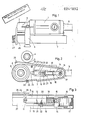
- an electric motor 1 is shown, on the output end of a reducing bevel gear 2 is flanged, which carries a handle 4 with a molded approach 3.
- Another handle 5 is flanged to the opposite end of the electric motor 1.
- a circuit board 6 is connected to the bevel gear 2 and the electric motor or the handle pieces 5 flanged to it, which is equipped with a cover plate 7 along most of its circumference, which leaves only parts of the grinding belt exposed.
- a drive roller 9 is provided along its circumference with a strong elastic layer 8.
- a guide piece 10 is connected, in the cylindrical bore of which a slide 11 is held axially displaceably, which prevents rotation by a screw 12 encompassing a roller is protected, which can roll in a guide slot 13 of the guide piece 10.
- the front end of the slide 11, flattened on both sides according to FIG. 2 engages in an extension of a U-shaped fork frame 14 and is held in this in a hinge-like manner by means of an articulated bolt 15.
- the fork ends are penetrated by an axle pin 16 on which a tensioning roller 17 'is mounted.
- the front end of the slider 11 is enclosed by a compression spring 18, one end of which is supported against an end face of the guide piece 10 and the other of which is supported against a face of the fork frame 14 and thus prestressed to the right in accordance with FIG. 2.
- the fork frame 14 is, as can also be seen in FIG. 3, provided with a control lever 19 which leads over the guide piece 10 and the slider 11, and the slotted end of which is penetrated by a stud screw 20 on which the control lever 19 prestressing compression spring 21 is provided.
- the control lever is held adjustable by a nut 22 of the stud 20, which engages in the slide 11 and passes through a slot in the guide piece 10. By adjusting the nut, the free end of the actuating lever 19 can be brought closer to the slider 11 or can be spread away by releasing it under the action of the compression spring 21, the fork frame 14 with its axle bolt 16 taking part in this movement, which acts as pivoting about the hinge pin 15 takes place, participates.
- the rear end of the slider 11 is screwed to a tab 23 which extends through an elongated hole 24 in the circuit board 6 and thus extends below it.
- a two-armed lever 25 which is not shown in FIG. 2, and one end of which engages behind the tab 23 at a short distance, that is, stands to the right of it, while its other end with one Handle 26 is equipped.
- the grinding belt 27 is stretched out between the drive roller 9 and the tensioning roller 17. As mentioned above, it is essentially overlapped laterally by the cover plate 7, so that it is only available for processing in a region of the circumference of the drive roller 9 and a subsequent region in which the circuit board 6 also withdraws.
- a bridge can be firmly attached, which points towards and away from the drawing plane, 'ends in axle bolts 28, on which rollers 29 are mounted.
- rollers it is possible, for example when guiding weld seams, cast seams or the like, to guide the belt grinding machine safely and parallel to the actual workpiece surface, so that the essential action is directed solely at the weld or cast seam.
- other devices can also be used, which on the one hand make it easier to maintain the distance to the surface to be machined, or on the other hand favor guidance on lateral lines or contours.
- a respective sanding belt 27 can be easily put on by the hand holding the handle 4 at the same time also spanning the handle 26 and pulling towards the handle 4.
- the two-armed angle lever 25 is pivoted, and its free lever arm shown in FIG. 3 lies against the tab 23 from the right as shown in FIG. 2 and pulls the slider 11 back against the force of the compression spring 18 thereon.
- the tensioning roller 17 is also retracted via the fork frame 14 and approached the drive roller 9, so that a grinding belt 27 to be inserted can be easily inserted.
- an inserted grinding belt 27 can also be easily loosened and removed by tightening the handle 26 and, if necessary, exchanged for another different grit.
- the sanding belt can show a tendency to migrate downwards or upwards according to FIG. 3.
- a tendency can be countered by adjusting the nut 2.2:
- the fork frame 14 and with it the axle bolt 16 of the tensioning roller 17 are pivoted against the vertical central plane which shows the axis of the drive roller 9, so that the tendency the lateral drainage can be countered by pivoting the axle pin 16.
- the measures necessary and appropriate for operation can therefore be carried out quickly and easily.
- the elastic layer 8 first of all offers an excellent, purely cylindrical base; However, it not only offers the sanding belt a particularly firm contact, which is sure to take it away, it is also capable of yielding in the event of local overloads, so that the service life of the sanding belt is achieved both by excluding local overloads and by dispensing with fixed, only friction and wear-related support surfaces is increased pleasingly and sudden free, disruptive particles due to wear are largely eliminated.
- FIGS. 4 to 6 A modified belt grinding machine is explained with reference to FIGS. 4 to 6, the reference numbers of parts already known from FIGS. 1 to 3 being adopted.
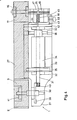
- FIG. 1 shows an electric motor 1 which, in a housing, shows a shaft 31 running in bearings 32, on which an armature 34, which is enclosed by a stationary field winding 33, is arranged.
- the required cooling is effected by a fan 35 also arranged on the shaft 31.
- the armature is supplied by brushes 36 resting on a collector.
- the housing is closed on the left-hand side by an angle piece 37, in which a spindle J'8 is mounted, which is driven by means of a ring gear 39, the teeth of which engage in the Gleason teeth 40 of the shaft 31.
- a drive roller 9 equipped with a strong elastic layer 8 is clamped onto the spindle 38 by means of a nut 41 and is encompassed by the grinding belt 27.
- the opposite end of the housing of the electric motor 1 is closed off by a base plate 42 which also carries a bearing 32 and which is connected by means of an adjusting bolt 44 to an adjusting plate 43 which rests over a large area on the base plate 42 and can be rotated slightly relative to the latter.
- the adjusting bolt 44 is designed as a double screw. 5 and 6 also show, the setting plate 43 is provided with lugs 45, the fork ends of which are penetrated by a clamping axis 46 which pivotally holds a clamping lever 47, which is equipped with a handle 26 and is connected to an axle pin 16 which is also a tensioning roller 17 mounted through the grinding belt 27.
- the tensioning lever 47 which can be pivoted in the directions of the double arrow 52, is pressed by means of a compression spring 18 against a stop, not shown, which can also be provided by the construction of the swivel joint determined by the tensioning axis 46.
- the compression spring is either in accordance with FIG. 4 at an attachment of the adjusting bolt 44 and / or according to FIG. 6 determined by a separate centering bolt 51 in its position.
- the base plate 42 is equipped with a threaded pin 49, in the thread of which an adjusting screw 48 can be set against a pressure plate 50 of the adjusting plate 43.
- the electric motor 1 is, according to FIG. 4, so close to the plane determined by the lower edge of the grinding belt 27 that parts of its housing pass through this plane. This achieves a particularly favorable position of the overall center of gravity, and on the other hand, separate support structures between the electric motor 1 and the sanding belt 27 can be dispensed with: the sanding belt runs over the drive roller 9 supported by the spindle 38 on one side, and on the opposite side it becomes the tensioning roller 17 is tensioned by means of the compression spring 18, and the support is ultimately carried out on the base plate 42 of the electric motor.
- the handle 26, the compression spring 18 can be compressed, and the axle pin 16 approaches the base plate, so that the grinding belt 27 can be easily removed, for example for replacement after advanced wear or for inserting another grit is.
- the adjusting plate 43 can be restricted against the base plate 42 in such a way that the desired running of the grinding belt 27 is adjusted and secured by correspondingly inclining the axle pin 16 of the tensioning roller.
- the adjusting screw 48 is expediently equipped with lock nuts (not shown in the drawings for the sake of simplicity) or loaded with them or their heads Constant grinding or locking devices equipped so that an adjustment can only be done deliberately and an unintentional adjustment is prevented.
- a separate circuit board between the grinding belt and the electric motor corresponding to the circuit board 6 of FIGS. 1 to 3 can also be expediently provided here, and it is recommended for safety and protection reasons that the areas of the circulation curve of the grinding belt that are not usually used for grinding are conveyed to cover a cover plate 7.
Landscapes
- Engineering & Computer Science (AREA)
- Mechanical Engineering (AREA)
- Finish Polishing, Edge Sharpening, And Grinding By Specific Grinding Devices (AREA)
Applications Claiming Priority (4)
| Application Number | Priority Date | Filing Date | Title |
|---|---|---|---|
| DE8610076U | 1986-04-14 | ||
| DE19868610076 DE8610076U1 (de) | 1986-04-14 | 1986-04-14 | Bandschleifmaschine |
| DE8624012U | 1986-09-08 | ||
| DE19868624012 DE8624012U1 (de) | 1986-09-08 | 1986-09-08 | Bandschleifmaschine |
Publications (2)
| Publication Number | Publication Date |
|---|---|
| EP0241892A2 true EP0241892A2 (fr) | 1987-10-21 |
| EP0241892A3 EP0241892A3 (fr) | 1989-08-09 |
Family
ID=25950821
Family Applications (1)
| Application Number | Title | Priority Date | Filing Date |
|---|---|---|---|
| EP87105430A Withdrawn EP0241892A3 (fr) | 1986-04-14 | 1987-04-13 | Ponceuse à bande |
Country Status (1)
| Country | Link |
|---|---|
| EP (1) | EP0241892A3 (fr) |
Cited By (16)
| Publication number | Priority date | Publication date | Assignee | Title |
|---|---|---|---|---|
| CN103273406A (zh) * | 2013-04-27 | 2013-09-04 | 苏州宏基工具有限公司 | 手持式电挫机 |
| CN107309792A (zh) * | 2017-06-02 | 2017-11-03 | 浙江森拉特暖通设备有限公司 | 金属圆管磨光设备的自动夹紧装置 |
| CN107336113A (zh) * | 2017-08-11 | 2017-11-10 | 安徽池州伟舜机电有限公司 | 一种砂带磨床的砂带驱动轴 |
| CN107344314A (zh) * | 2017-08-11 | 2017-11-14 | 安徽池州伟舜机电有限公司 | 一种砂带磨床的工件夹紧机构 |
| CN108326694A (zh) * | 2016-07-13 | 2018-07-27 | 安溪县中磊设备制造有限公司 | 一种钢板修磨机 |
| CN109531369A (zh) * | 2019-01-07 | 2019-03-29 | 浙江机电职业技术学院 | 一种手持式自动打磨装置 |
| CN110561238A (zh) * | 2019-10-11 | 2019-12-13 | 宜兴市九洲封头锻造有限公司 | 一种轻便型砂带式封头打磨机 |
| CN110774132A (zh) * | 2019-12-07 | 2020-02-11 | 安徽芜湖海螺建筑安装工程有限责任公司 | 一种应用于回转窑托轮在线动态修复的设备 |
| CN111172829A (zh) * | 2020-03-04 | 2020-05-19 | 中国铁道科学研究院集团有限公司铁道建筑研究所 | 一种铁路钢轨焊缝砂带打磨装置 |
| CN111469023A (zh) * | 2020-05-21 | 2020-07-31 | 南京湛泸科技有限公司 | 一种机床用砂带机 |
| CN112123123A (zh) * | 2020-10-19 | 2020-12-25 | 上海交通大学 | 一种机器人末端砂带机 |
| CN112658914A (zh) * | 2020-12-24 | 2021-04-16 | 上海易新冶金设备制造有限公司 | 一种普通车床的打磨机构 |
| CN113059449A (zh) * | 2021-04-14 | 2021-07-02 | 南京林业大学 | 一种家具连接榫头木结构成型精加工处理设备 |
| CN114393484A (zh) * | 2022-01-10 | 2022-04-26 | 中国铁道科学研究院集团有限公司铁道建筑研究所 | 一种小型钢轨焊缝打磨机 |
| CN119369248A (zh) * | 2024-12-30 | 2025-01-28 | 济南恒运昌锻造有限公司 | 一种摩托车曲轴曲柄打磨装置 |
| CN120985490A (zh) * | 2025-10-24 | 2025-11-21 | 大连誉洋工业智能有限公司 | 便于更换磨具的磨床及其磨具更换方法 |
Family Cites Families (8)
| Publication number | Priority date | Publication date | Assignee | Title |
|---|---|---|---|---|
| DE7109286U (de) * | 1971-06-24 | Stoll K Kg | Als Handgerat ausgebildete Bandschleif maschine, ins besondere Einhandbandschleif maschine | |
| DE1628783U (de) * | 1951-06-23 | 1951-10-04 | Daimler Benz Ag | Anbaugeraet fuer handschleifmaschinen. |
| BE564827A (fr) * | 1957-03-01 | |||
| US3334447A (en) * | 1965-09-28 | 1967-08-08 | Treffle J Leveque | Sanding machine |
| DE1652197A1 (de) * | 1967-07-08 | 1971-11-25 | Schmid & Wezel | Bandschleifgeraet |
| US4178723A (en) * | 1978-09-05 | 1979-12-18 | Dynabrade, Inc. | Guide wheels for belt grinder |
| US4368597A (en) * | 1980-08-28 | 1983-01-18 | Dynabrade, Inc. | Miniature belt grinder |
| DE8610076U1 (de) * | 1986-04-14 | 1986-07-10 | Jörg, Hermann-Josef, 5241 Molzheim | Bandschleifmaschine |
-
1987
- 1987-04-13 EP EP87105430A patent/EP0241892A3/fr not_active Withdrawn
Cited By (19)
| Publication number | Priority date | Publication date | Assignee | Title |
|---|---|---|---|---|
| CN103273406B (zh) * | 2013-04-27 | 2016-02-03 | 苏州宏基工具有限公司 | 手持式电挫机 |
| CN103273406A (zh) * | 2013-04-27 | 2013-09-04 | 苏州宏基工具有限公司 | 手持式电挫机 |
| CN108326694B (zh) * | 2016-07-13 | 2020-12-18 | 浙江雷诺尔电气有限公司 | 一种钢板修磨机 |
| CN108326694A (zh) * | 2016-07-13 | 2018-07-27 | 安溪县中磊设备制造有限公司 | 一种钢板修磨机 |
| CN107309792A (zh) * | 2017-06-02 | 2017-11-03 | 浙江森拉特暖通设备有限公司 | 金属圆管磨光设备的自动夹紧装置 |
| CN107309792B (zh) * | 2017-06-02 | 2023-09-01 | 浙江森拉特暖通设备有限公司 | 金属圆管磨光设备的自动夹紧装置 |
| CN107336113A (zh) * | 2017-08-11 | 2017-11-10 | 安徽池州伟舜机电有限公司 | 一种砂带磨床的砂带驱动轴 |
| CN107344314A (zh) * | 2017-08-11 | 2017-11-14 | 安徽池州伟舜机电有限公司 | 一种砂带磨床的工件夹紧机构 |
| CN109531369A (zh) * | 2019-01-07 | 2019-03-29 | 浙江机电职业技术学院 | 一种手持式自动打磨装置 |
| CN110561238A (zh) * | 2019-10-11 | 2019-12-13 | 宜兴市九洲封头锻造有限公司 | 一种轻便型砂带式封头打磨机 |
| CN110774132A (zh) * | 2019-12-07 | 2020-02-11 | 安徽芜湖海螺建筑安装工程有限责任公司 | 一种应用于回转窑托轮在线动态修复的设备 |
| CN111172829A (zh) * | 2020-03-04 | 2020-05-19 | 中国铁道科学研究院集团有限公司铁道建筑研究所 | 一种铁路钢轨焊缝砂带打磨装置 |
| CN111469023A (zh) * | 2020-05-21 | 2020-07-31 | 南京湛泸科技有限公司 | 一种机床用砂带机 |
| CN112123123A (zh) * | 2020-10-19 | 2020-12-25 | 上海交通大学 | 一种机器人末端砂带机 |
| CN112658914A (zh) * | 2020-12-24 | 2021-04-16 | 上海易新冶金设备制造有限公司 | 一种普通车床的打磨机构 |
| CN113059449A (zh) * | 2021-04-14 | 2021-07-02 | 南京林业大学 | 一种家具连接榫头木结构成型精加工处理设备 |
| CN114393484A (zh) * | 2022-01-10 | 2022-04-26 | 中国铁道科学研究院集团有限公司铁道建筑研究所 | 一种小型钢轨焊缝打磨机 |
| CN119369248A (zh) * | 2024-12-30 | 2025-01-28 | 济南恒运昌锻造有限公司 | 一种摩托车曲轴曲柄打磨装置 |
| CN120985490A (zh) * | 2025-10-24 | 2025-11-21 | 大连誉洋工业智能有限公司 | 便于更换磨具的磨床及其磨具更换方法 |
Also Published As
| Publication number | Publication date |
|---|---|
| EP0241892A3 (fr) | 1989-08-09 |
Similar Documents
| Publication | Publication Date | Title |
|---|---|---|
| EP0241892A2 (fr) | Ponceuse à bande | |
| EP0455142A2 (fr) | Machine à meuler des profilés | |
| DE69008351T2 (de) | Vorrichtung zum schleifen ebener flächen an werkzeugen. | |
| EP0467383A1 (fr) | Dispositif d'affûtage | |
| DE1777187B2 (de) | Spitzenlose schleifmaschine zum schleifen von langgestreckten stangen unterschiedlicher durchmesser im durchlaufverfahren | |
| DE2538209A1 (de) | Doppelspindel-flachschleifmaschine | |
| EP0121609A2 (fr) | Machine universelle pour le travail du bois et de la matière plastique | |
| DE2908392C2 (de) | Handtrennschleifmaschine zum Zerteilen von Schienen | |
| DE3216929A1 (de) | Vorrichtung zum entgraten von werkstuecken | |
| DE623090C (de) | Vorschubvorrichtung fuer Holzbearbeitungsmaschinen | |
| DE19627541A1 (de) | Zubehörset für eine Werkzeugmaschine | |
| DE4432974B4 (de) | Handgeführter, elektrischer Bandschleifer | |
| DE3447379A1 (de) | Vorrichtung zum fuehren einer handschleifmaschine | |
| DE8610076U1 (de) | Bandschleifmaschine | |
| DE4344997A1 (de) | Rahmenhalterung für Kantenbearbeitungswerkzeuge | |
| EP0027219B1 (fr) | Ponçeuse à bande portative avec cadre de guidage | |
| EP0358059B1 (fr) | Dispositif d'affilage | |
| DE956984C (de) | Hand-Motorsaege fuer die Bearbeitung wellenfoermiger Stoffe | |
| DE19704088A1 (de) | Handbandschleifer | |
| DE1955787U (de) | Schleifvorrichtung fuer elektroden. | |
| EP0201810A2 (fr) | Dispositif de meulage d'un produit semi-fini | |
| DE8332614U1 (de) | Gerät zum Be- bzw. Nacharbeiten der Stahlkanten von Schiern | |
| DE1527095C (de) | Profilhobelstahl oder Profilschneidstahl für eine Verzahnungsmaschine | |
| DE3305605A1 (de) | Vorrichtung zum rundschleifen von werkstuecken | |
| AT224333B (de) | Verfahren und Vorrichtung zum Schärfen von Räumzahnsägeketten |
Legal Events
| Date | Code | Title | Description |
|---|---|---|---|
| PUAI | Public reference made under article 153(3) epc to a published international application that has entered the european phase |
Free format text: ORIGINAL CODE: 0009012 |
|
| 17P | Request for examination filed |
Effective date: 19870512 |
|
| AK | Designated contracting states |
Kind code of ref document: A2 Designated state(s): AT BE CH DE ES FR GB IT LI LU NL SE |
|
| RBV | Designated contracting states (corrected) |
Designated state(s): AT CH DE LI |
|
| PUAL | Search report despatched |
Free format text: ORIGINAL CODE: 0009013 |
|
| AK | Designated contracting states |
Kind code of ref document: A3 Designated state(s): AT CH DE LI |
|
| STAA | Information on the status of an ep patent application or granted ep patent |
Free format text: STATUS: THE APPLICATION IS DEEMED TO BE WITHDRAWN |
|
| 18D | Application deemed to be withdrawn |
Effective date: 19891103 |