EP0242005B1 - Assemblage pour le montage de modules électroniques - Google Patents
Assemblage pour le montage de modules électroniques Download PDFInfo
- Publication number
- EP0242005B1 EP0242005B1 EP19870200708 EP87200708A EP0242005B1 EP 0242005 B1 EP0242005 B1 EP 0242005B1 EP 19870200708 EP19870200708 EP 19870200708 EP 87200708 A EP87200708 A EP 87200708A EP 0242005 B1 EP0242005 B1 EP 0242005B1
- Authority
- EP
- European Patent Office
- Prior art keywords
- electronics module
- mounting assembly
- heat sink
- module mounting
- sink plate
- Prior art date
- Legal status (The legal status is an assumption and is not a legal conclusion. Google has not performed a legal analysis and makes no representation as to the accuracy of the status listed.)
- Expired
Links
- 239000000919 ceramic Substances 0.000 claims description 4
- 238000001125 extrusion Methods 0.000 claims description 4
- 229910000838 Al alloy Inorganic materials 0.000 claims description 3
- XAGFODPZIPBFFR-UHFFFAOYSA-N aluminium Chemical compound [Al] XAGFODPZIPBFFR-UHFFFAOYSA-N 0.000 claims description 3
- 229910052782 aluminium Inorganic materials 0.000 claims description 3
- 239000004411 aluminium Substances 0.000 claims description 3
- 239000010935 stainless steel Substances 0.000 claims description 3
- 229910001220 stainless steel Inorganic materials 0.000 claims description 3
- 238000000034 method Methods 0.000 claims description 2
- 239000000463 material Substances 0.000 description 3
- 101100334009 Caenorhabditis elegans rib-2 gene Proteins 0.000 description 2
- 238000009434 installation Methods 0.000 description 2
- 238000010276 construction Methods 0.000 description 1
- 230000017525 heat dissipation Effects 0.000 description 1
- 238000010438 heat treatment Methods 0.000 description 1
- 238000003754 machining Methods 0.000 description 1
- 238000004519 manufacturing process Methods 0.000 description 1
- 238000012986 modification Methods 0.000 description 1
- 230000004048 modification Effects 0.000 description 1
- 238000012856 packing Methods 0.000 description 1
- 230000000717 retained effect Effects 0.000 description 1
Images
Classifications
-
- H—ELECTRICITY
- H05—ELECTRIC TECHNIQUES NOT OTHERWISE PROVIDED FOR
- H05K—PRINTED CIRCUITS; CASINGS OR CONSTRUCTIONAL DETAILS OF ELECTRIC APPARATUS; MANUFACTURE OF ASSEMBLAGES OF ELECTRICAL COMPONENTS
- H05K7/00—Constructional details common to different types of electric apparatus
- H05K7/20—Modifications to facilitate cooling, ventilating, or heating
- H05K7/20536—Modifications to facilitate cooling, ventilating, or heating for racks or cabinets of standardised dimensions, e.g. electronic racks for aircraft or telecommunication equipment
- H05K7/20545—Natural convection of gaseous coolant; Heat transfer by conduction from electronic boards
Definitions
- This invention relates to a mounting assembly for electronics modules and more especially it relates to an assembly which facilitates the mounting of modules such as ceramic tiles carrying electronics components in stacked fashion one above the other within a rack.
- each rib is formed integrally with the heat sink plate, each rib comprising an elongate channel section adapted at each end to define a ramp, the open sides of each channel section being narrowed thereby to form a neck portion which serves to retain within the channel section an elongate member, which at one end is secured to a first clamp member and which at the other end is screw threaded to receive a nut which is arranged to bear against a second clamp member, such that when the nut is tightenend the clamp members at opposite ends of each channel section are constrained to move toward each other up the ramps, whereby in use the assembly is clamped within opposite slots of a mounting rack by means of the clamp members which serve to maintain the ribs in intimate contact with the walls of the slot and thereby facilitate heat transfer from the ribs to the rack by conduction.
- the first clamp member may comprise a short bar of circular cross-section secured to the elongate member transversely so that its circular periphery makes contact with the ramp along a line parallel to that axis of the bar which is coaxial with the circular periphery.
- the second clamp member may comprise a bar of part circular cross-section the circular portion of which is arranged in contact with an adjacent ramp and a flat portion of which is arranged to co-operate with the nut.
- the heat sink plate and ribs may be constructed of aluminium or an aluminium alloy and formed integrally by means of an extrusion process for example.
- the nut, the clamp members or the elongate member may be constructed of stainless steel.
- the mounting assembly may comprise a ceramic tile module secured to and supported by the heat sink plate.
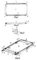
- a mounting assembly for an electronics module comprises a heat sink plate 1 which is formed integrally between a pair of ribs 2 and 3.
- an enlarged sectional view of the rib 2 is shown in Figure 3 and it comprises a channel 4 having a narrow neck portion 5, the heat sink plate 1 being arranged to extend orthogonally of the rib intermediate between the narrow neck portion 5 and a clamping surface 6.
- each rib is machined to form ramps 7 and 8 at each end of the rib 2 and ramps 9 and 10 at each end of the rib 3.
- an elongate member or stud 11 which is threaded at each end is located within the channel section of the ribs 2 and 3 and retained therein by means of the narrow neck portion 5 as shown in Figure 3.
- first clamp members 12 and 13 are secured at one end of studs 14 and 15 respectively and nuts 16 and 17 are fitted to the other ends of the studs 14 and 15 so as to urge further clamping members 18 and 19 against ramps 20 and 21.
- the clamping members 18 and 19 tend to advance up the ramps 20 and 21.
- the clamping members 12 and 13 are constrained to advance up ramps 22 and 23 at ends of ribs 24 and 25 remote from the nuts 16 and 17.
- a heat sink plate 26 formed integrally with the ribs 24 and 25 is used to support a ceramic tile module on which electronics components are mounted.
- connector sockets 27 and 28 are provided in order to make electrical contact with the electronics components.
- the heat sink plate and the ribs are conveniently fabricated from aluminium or an aluminium alloy.
- the nuts, clamps and studs on the other hand are fabricated from stainless steel. Since the heating plate and the ribs are fabricated as one extrusion they are particularly rigid and little finishing cost is incurred.
- the clamps 12 and 13 are fabricated from rod material which is inexpensive to provide and the clamps 18 and 19 are fabricated from similar material with minimal machining. It will be appreciated that installation is facilitated since the clamps have no projecting sharp edges. Since the clamps are disposed approximately centrally they have no chance of rotating out of alignment whereby installation would be prevented. By using dissimilar materials for the construction of the clamps and the ramps the occurrence of pressure welded joins is obviated.
Landscapes
- Engineering & Computer Science (AREA)
- Aviation & Aerospace Engineering (AREA)
- Physics & Mathematics (AREA)
- Thermal Sciences (AREA)
- Microelectronics & Electronic Packaging (AREA)
- Cooling Or The Like Of Electrical Apparatus (AREA)
- Cooling Or The Like Of Semiconductors Or Solid State Devices (AREA)
Claims (6)
- Ensemble de montage de modules électroniques, comprenant une plaque rigide (26) de radiateur destinée à supporter un module électronique, la plaque de radiateur (26) étant placée entre deux nervures parallèles (24, 25) qui, pendant l'utilisation se logent dans des fentes juxtaposées formées dans un râtelier de montage, caractérisé en ce que chaque nervure (24, 25) est formée en une seule pièce avec la plaque de radiateur (26), chaque nervure (24, 25) comprenant un tronçon allongé (4) en forme de canal destiné à délimiter une rampe (20, 22, 21, 23) à chaque extrémité, les côtés ouverts de chaque tronçon de canal étant rétrécis et formant une partie (5) de col qui est destinée à retenir, dans le tronçon de canal (24, 25), un organe allongé (14, 15) qui est fixé, à une première extrémité, à un premier organe de serrage (12, 13) et qui, à l'autre extrémité, est fileté pour coopérer avec un écrou (16, 17) qui est destiné à être en appui contre un second organe de serrage (18, 19), si bien que, lorsque l'écrou (16, 17) est serré, les organes de serrage (12, 18, 13, 19) des extrémités opposées de chaque tronçon de canal (24, 25) sont obligés de se rapprocher en remontant le long des rampes (22, 20, 23, 21), si bien que, pendant l'utilisation, l'ensemble est serré dans les lentes opposées du râtelier de montage par les organes de serrage dont le rôle est de maintenir les nervures en contact intime avec les parois de la lente et de faciliter ainsi le transfert de chaleur des nervures au râtelier par conduction.
- Ensemble de montage de modules électroniques selon la revendication 1, dans lequel le premier organe de serrage comporte une courte barre de section circulaire, fixée à l'organe allongé transversalement afin que sa périphérie circulaire soit au contact de la rampe le long d'un axe parallèle à l'axe de la barre qui est coaxial à la périphérie circulaire.
- Ensemble de montage de modules électroniques selon la revendication 1 ou 2, dans lequel le second organe de serrage comporte une barre de section partiellement circulaire, dont la partie circulaire est destinée à être au contact d'une rampe adjacente et dont une partie plate est destinée à coopérer avec l'écrou.
- Ensemble de montage de modules électroniques selon l'une quelconque des revendications 1 à 3, dans lequel la plaque de radiateur et les nervures sont formées d'aluminium ou d'un alliage d'aluminium et sont formées en une seule pièce par une opération d'extrusion.
- Ensemble de montage de modules électroniques selon l'une quelconque des revendications 1 à 4, dans lequel l'écrou, les organes de serrage ou l'organe allongé sont formés d'acier inoxydable.
- Ensemble de montage de modules électroniques selon l'une quelconque des revendications 1 à 5, l'ensemble comprenant un module à support céramique fixé à la plaque de radiateur et supporté par celle-ci.
Applications Claiming Priority (1)
| Application Number | Priority Date | Filing Date | Title |
|---|---|---|---|
| GB8608723A GB2189085B (en) | 1986-04-10 | 1986-04-10 | Electronics module mounting assembly |
Publications (3)
| Publication Number | Publication Date |
|---|---|
| EP0242005A2 EP0242005A2 (fr) | 1987-10-21 |
| EP0242005A3 EP0242005A3 (en) | 1988-05-11 |
| EP0242005B1 true EP0242005B1 (fr) | 1991-10-23 |
Family
ID=10595972
Family Applications (1)
| Application Number | Title | Priority Date | Filing Date |
|---|---|---|---|
| EP19870200708 Expired EP0242005B1 (fr) | 1986-04-10 | 1987-04-15 | Assemblage pour le montage de modules électroniques |
Country Status (4)
| Country | Link |
|---|---|
| EP (1) | EP0242005B1 (fr) |
| DE (1) | DE3773975D1 (fr) |
| ES (1) | ES2026520T3 (fr) |
| GB (1) | GB2189085B (fr) |
Families Citing this family (4)
| Publication number | Priority date | Publication date | Assignee | Title |
|---|---|---|---|---|
| US4819713A (en) * | 1987-04-23 | 1989-04-11 | Calmark Corporation | Retainer for electronic modules |
| US6545375B2 (en) * | 2001-02-20 | 2003-04-08 | Ralph L. Hollis, Jr. | Field-joinable platen tiles for planar motors |
| NL1022633C2 (nl) | 2003-02-10 | 2004-08-12 | Keltub B V | Verbeterde schuimvormingseenheid. |
| US20080037231A1 (en) * | 2006-08-14 | 2008-02-14 | Honeywell International Inc. | Heat Transferring Guide for Electronic Cards |
Family Cites Families (7)
| Publication number | Priority date | Publication date | Assignee | Title |
|---|---|---|---|---|
| GB2052164B (en) * | 1979-06-30 | 1983-12-07 | Burroughs Corp | Assemblies of electrical components |
| US4298904A (en) * | 1979-12-17 | 1981-11-03 | The Boeing Company | Electronic conduction cooling clamp |
| US4354770A (en) * | 1980-05-19 | 1982-10-19 | The United States Of America As Represented By The Secretary Of The Navy | Wedge assembly |
| US4318157A (en) * | 1980-06-06 | 1982-03-02 | Control Data Corporation | Apparatus for mounting circuit cards |
| GB2102209A (en) * | 1981-07-17 | 1983-01-26 | Marconi Avionics | Clamp arrangements for cooling electrical circuits |
| DE3147790A1 (de) * | 1981-12-03 | 1983-06-09 | Brown, Boveri & Cie Ag, 6800 Mannheim | Leistungsmodul und verfahren zu seiner herstellung |
| GB2111758B (en) * | 1981-12-17 | 1985-07-31 | Standard Telephones Cables Ltd | Plug in module connector mount |
-
1986
- 1986-04-10 GB GB8608723A patent/GB2189085B/en not_active Expired
-
1987
- 1987-04-15 EP EP19870200708 patent/EP0242005B1/fr not_active Expired
- 1987-04-15 DE DE8787200708T patent/DE3773975D1/de not_active Expired - Fee Related
- 1987-04-15 ES ES87200708T patent/ES2026520T3/es not_active Expired - Lifetime
Also Published As
| Publication number | Publication date |
|---|---|
| DE3773975D1 (de) | 1991-11-28 |
| GB2189085B (en) | 1989-11-22 |
| GB8608723D0 (en) | 1986-05-14 |
| EP0242005A3 (en) | 1988-05-11 |
| ES2026520T3 (es) | 1992-05-01 |
| GB2189085A (en) | 1987-10-14 |
| EP0242005A2 (fr) | 1987-10-21 |
Similar Documents
| Publication | Publication Date | Title |
|---|---|---|
| US4298904A (en) | Electronic conduction cooling clamp | |
| US4994937A (en) | Hydraulic thermal clamp for electronic modules | |
| US5883784A (en) | Mounting structure for heat conductively supporting a planar electric device | |
| EP0258312B1 (fr) | Agencement de montage pour dispositifs a semi-conducteurs | |
| US6435888B1 (en) | Captive splice assembly for electrical bus and method for using same | |
| US5184281A (en) | Heat dissipation apparatus | |
| EP0625871B1 (fr) | Attachement pour dissipateur de chaleur pour un composant électronique utilisant un ressort hélicoidal du type incliné | |
| US4273465A (en) | Pipe clamp | |
| US4971570A (en) | Wedge clamp thermal connector | |
| US4640571A (en) | Electrical connector blocks | |
| JPH04250697A (ja) | ラックにモジュールを保持するウェッジ・クランプ | |
| US4638404A (en) | Clamping device for plate-shaped semiconductor components | |
| EP0242005B1 (fr) | Assemblage pour le montage de modules électroniques | |
| US3767058A (en) | Mounting arrangements | |
| US3699393A (en) | Printed wiring card file | |
| EP0123910B1 (fr) | Bloc de connexion pour appareil électrique | |
| US4205892A (en) | Panelboard having connector means for making plug-in and bolted connections with circuit breaker line terminals | |
| US4693303A (en) | Liquid cooling module with springy contact elements and an aperture plate slidable thereover | |
| EP0594544B1 (fr) | Adaptateur pour raccorder un commutateur polyphasé en forme de boîte sur des barres omnibus parallèles | |
| US4832627A (en) | Input adapter for a bus bar system | |
| JP2546030Y2 (ja) | 集積回路冷却用ヒートパイプの受熱ブロック | |
| JPS6324699A (ja) | プリント回路基板取付け装置 | |
| US4616896A (en) | Connecting terminal for printed circuit board | |
| EP0251557B1 (fr) | Assemblage de connexions pour barres omnibus | |
| US2477523A (en) | Electrical bus structure |
Legal Events
| Date | Code | Title | Description |
|---|---|---|---|
| PUAI | Public reference made under article 153(3) epc to a published international application that has entered the european phase |
Free format text: ORIGINAL CODE: 0009012 |
|
| AK | Designated contracting states |
Kind code of ref document: A2 Designated state(s): DE ES FR IT NL SE |
|
| PUAL | Search report despatched |
Free format text: ORIGINAL CODE: 0009013 |
|
| AK | Designated contracting states |
Kind code of ref document: A3 Designated state(s): DE ES FR IT NL SE |
|
| 17P | Request for examination filed |
Effective date: 19881007 |
|
| 17Q | First examination report despatched |
Effective date: 19900628 |
|
| RAP1 | Party data changed (applicant data changed or rights of an application transferred) |
Owner name: GEC-MARCONI LIMITED |
|
| GRAA | (expected) grant |
Free format text: ORIGINAL CODE: 0009210 |
|
| AK | Designated contracting states |
Kind code of ref document: B1 Designated state(s): DE ES FR IT NL SE |
|
| ITF | It: translation for a ep patent filed | ||
| REF | Corresponds to: |
Ref document number: 3773975 Country of ref document: DE Date of ref document: 19911128 |
|
| ET | Fr: translation filed | ||
| REG | Reference to a national code |
Ref country code: ES Ref legal event code: FG2A Ref document number: 2026520 Country of ref document: ES Kind code of ref document: T3 |
|
| PLBE | No opposition filed within time limit |
Free format text: ORIGINAL CODE: 0009261 |
|
| STAA | Information on the status of an ep patent application or granted ep patent |
Free format text: STATUS: NO OPPOSITION FILED WITHIN TIME LIMIT |
|
| 26N | No opposition filed | ||
| PGFP | Annual fee paid to national office [announced via postgrant information from national office to epo] |
Ref country code: ES Payment date: 19930406 Year of fee payment: 7 |
|
| PGFP | Annual fee paid to national office [announced via postgrant information from national office to epo] |
Ref country code: FR Payment date: 19930408 Year of fee payment: 7 |
|
| PGFP | Annual fee paid to national office [announced via postgrant information from national office to epo] |
Ref country code: SE Payment date: 19930419 Year of fee payment: 7 |
|
| PGFP | Annual fee paid to national office [announced via postgrant information from national office to epo] |
Ref country code: DE Payment date: 19930421 Year of fee payment: 7 |
|
| PGFP | Annual fee paid to national office [announced via postgrant information from national office to epo] |
Ref country code: NL Payment date: 19930430 Year of fee payment: 7 |
|
| PG25 | Lapsed in a contracting state [announced via postgrant information from national office to epo] |
Ref country code: SE Effective date: 19940416 Ref country code: ES Free format text: LAPSE BECAUSE OF NON-PAYMENT OF DUE FEES Effective date: 19940416 |
|
| PG25 | Lapsed in a contracting state [announced via postgrant information from national office to epo] |
Ref country code: NL Effective date: 19941101 |
|
| NLV4 | Nl: lapsed or anulled due to non-payment of the annual fee | ||
| PG25 | Lapsed in a contracting state [announced via postgrant information from national office to epo] |
Ref country code: FR Effective date: 19941229 |
|
| PG25 | Lapsed in a contracting state [announced via postgrant information from national office to epo] |
Ref country code: DE Effective date: 19950103 |
|
| EUG | Se: european patent has lapsed |
Ref document number: 87200708.3 Effective date: 19941110 |
|
| REG | Reference to a national code |
Ref country code: FR Ref legal event code: ST |
|
| REG | Reference to a national code |
Ref country code: ES Ref legal event code: FD2A Effective date: 19990201 |
|
| PG25 | Lapsed in a contracting state [announced via postgrant information from national office to epo] |
Ref country code: IT Free format text: LAPSE BECAUSE OF NON-PAYMENT OF DUE FEES;WARNING: LAPSES OF ITALIAN PATENTS WITH EFFECTIVE DATE BEFORE 2007 MAY HAVE OCCURRED AT ANY TIME BEFORE 2007. THE CORRECT EFFECTIVE DATE MAY BE DIFFERENT FROM THE ONE RECORDED. Effective date: 20050415 |