EP0242433A2 - Chaise avec siège et dossier inclinables à effet de ressort - Google Patents
Chaise avec siège et dossier inclinables à effet de ressort Download PDFInfo
- Publication number
- EP0242433A2 EP0242433A2 EP86113762A EP86113762A EP0242433A2 EP 0242433 A2 EP0242433 A2 EP 0242433A2 EP 86113762 A EP86113762 A EP 86113762A EP 86113762 A EP86113762 A EP 86113762A EP 0242433 A2 EP0242433 A2 EP 0242433A2
- Authority
- EP
- European Patent Office
- Prior art keywords
- seat
- chair
- chair according
- piece
- shell
- Prior art date
- Legal status (The legal status is an assumption and is not a legal conclusion. Google has not performed a legal analysis and makes no representation as to the accuracy of the status listed.)
- Granted
Links
Images


Classifications
-
- A—HUMAN NECESSITIES
- A47—FURNITURE; DOMESTIC ARTICLES OR APPLIANCES; COFFEE MILLS; SPICE MILLS; SUCTION CLEANERS IN GENERAL
- A47C—CHAIRS; SOFAS; BEDS
- A47C7/00—Parts, details, or accessories of chairs or stools
- A47C7/36—Supports for the head or the back
- A47C7/40—Supports for the head or the back for the back
- A47C7/44—Supports for the head or the back for the back with elastically-mounted frame
- A47C7/441—Supports for the head or the back for the back with elastically-mounted frame with adjustable elasticity
-
- A—HUMAN NECESSITIES
- A47—FURNITURE; DOMESTIC ARTICLES OR APPLIANCES; COFFEE MILLS; SPICE MILLS; SUCTION CLEANERS IN GENERAL
- A47C—CHAIRS; SOFAS; BEDS
- A47C3/00—Chairs characterised by structural features; Chairs or stools with rotatable or vertically-adjustable seats
- A47C3/02—Rocking chairs
- A47C3/021—Rocking chairs having elastic frames
-
- A—HUMAN NECESSITIES
- A47—FURNITURE; DOMESTIC ARTICLES OR APPLIANCES; COFFEE MILLS; SPICE MILLS; SUCTION CLEANERS IN GENERAL
- A47C—CHAIRS; SOFAS; BEDS
- A47C3/00—Chairs characterised by structural features; Chairs or stools with rotatable or vertically-adjustable seats
- A47C3/02—Rocking chairs
- A47C3/025—Rocking chairs with seat, or seat and back-rest unit, elastically mounted in a rigid frame
-
- A—HUMAN NECESSITIES
- A47—FURNITURE; DOMESTIC ARTICLES OR APPLIANCES; COFFEE MILLS; SPICE MILLS; SUCTION CLEANERS IN GENERAL
- A47C—CHAIRS; SOFAS; BEDS
- A47C3/00—Chairs characterised by structural features; Chairs or stools with rotatable or vertically-adjustable seats
- A47C3/12—Chairs characterised by structural features; Chairs or stools with rotatable or vertically-adjustable seats with shell-shaped seat and back-rest unit, e.g. having arm-rests
-
- A—HUMAN NECESSITIES
- A47—FURNITURE; DOMESTIC ARTICLES OR APPLIANCES; COFFEE MILLS; SPICE MILLS; SUCTION CLEANERS IN GENERAL
- A47C—CHAIRS; SOFAS; BEDS
- A47C7/00—Parts, details, or accessories of chairs or stools
- A47C7/36—Supports for the head or the back
- A47C7/40—Supports for the head or the back for the back
- A47C7/44—Supports for the head or the back for the back with elastically-mounted frame
- A47C7/445—Supports for the head or the back for the back with elastically-mounted frame with bar or leaf springs
Definitions
- the invention relates to a chair, the chair frame is provided with fastening elements in the region of the front edge of the seat for pivotably fastening the seat and back, the seat and back being resiliently movable relative to one another.
- the seat can be pivoted both in the area of its front and its rear end about axes directed parallel to the front and rear seat edges, and the back of the chair is designed separately from the seat and can be pivoted in this way that the so-called seat angle opening, ie the angle between the seat and back, can be changed within relatively wide limits if the person sitting on the chair changes his position, for example, wants to change from a straight sitting position to a position leaning far back. Ergonomic studies have shown that this is particularly advantageous in order to counteract signs of fatigue by the fact that the spine is well supported by the back of the chair in all seated positions.
- such a chair has a relatively complicated structure.
- So-called cantilever chairs are also known, i.e. those in which the chair frame, seat and back are formed from continuous resilient tubular profiles, which, although simple in construction, also allow a relatively good adaptation to different sitting postures, but are still disadvantageous insofar as they lean far behind Person possessing the chair, the area of the front edge of the seat is shifted downwards and thus also the position of the person concerned in relation to surrounding furniture, in particular table tops.
- the change in the seat angle opening is limited and a bowl-shaped design of the seat and back is not possible.
- the object of the invention is to provide a solution which, regardless of the design of the chair frame, ie regardless of whether it is designed as a possibly rolling bogie or with rigid chair legs, an adaptation of the seat and back to the respective sitting posture of the person using the chair makes possible with much less effort and at the same time creates the conditions for the change in continuing education Seat angle opening, ie the angle between the seat and back, can be made particularly effectively and easily.
- this object is basically first achieved in that a one-piece supporting structure for the seat and back, which is designed as a separate component, is clamped so firmly only at the front end of the seat part that the seat and back as a whole are due to their own resilience Support structure around the front edge of the seat are resiliently pivotable.
- the seat and back can be easily adapted to the seated position in each case, similar to the case with a cantilever chair, as already mentioned above, first by lowering the rear end of the seat in the case of a backrest of the seated person, and a simultaneous enlargement of the seat angle opening due to the resilient mobility between seat and back.
- the cross is reduced to reinforce the resilient adjustability between seat and back section or a corresponding shape of the one-piece support structure for the seat and back in the transition area between them, whereby there is a particularly good reinforcing effect if the location of the resilient adjustability is provided on the support structure in the region of the rear end before it is bent towards the back.
- a horizontal one-sided indentation of the shell can be provided or a double-sided waist-like retraction of the shell, as is often the case with chairs with a one-piece seat and back shell, the seat of which is fastened to the chair frame so that it cannot be pivoted.
- a chair is known with a seat shell consisting of a seat part and backrest part (DE-GM 75 00 152), in which a recess is provided in the seat shell, which is arranged approximately parallel to the front edge of the seatback in the area of the transition to the seat part in the backrest part Slit and two further slits opening into this, which are approximately perpendicular to the first-mentioned slot and extend approximately to the region of the front edge of the seat shell, such that the recess has approximately the shape of a U.
- the slot in question must be covered by an elastic pad if it is intended to prevent bruising of the buttocks of the person sitting on the chair.
- Such a slot configuration cannot therefore be used for a shell construction without additional padding or the like, which also means that the above-described incision configuration according to the invention is not limited to an overall pivotable seat and back shell, but with the same advantage even with one can find such application, the seat of which is firmly attached to the chair frame, as in the chair according to DE-GM 75 00 152.
- a structurally particularly simple configuration is obtained if the resilient clamping of the one-piece shell on the chair frame is formed by resting and fastening the front end of the seat on a crossbar attached to the chair frame.
- the traverse can be formed by a substantially horizontally arranged plate, such that there is a correspondingly wide contact surface of the shell on the crossbar.
- the upper rear edge of the plate be rounded, so that there is no notch in the area of the shell opposite the upper rear edge during the pivoting movement of the shell.
- rear chair legs which are only slightly downwardly inclined from the crossbeam, branched beneath the seat part of the one-piece shell and oriented essentially vertically from the end of the seat part.
- the relevant rear chair legs can be connected to the crossmember in a structurally particularly simple manner and nevertheless do not prevent the one-piece shell from pivoting downward in the region of the seat.
- the chair frame can also be designed to be height-adjustable and / or rotatable, in which case a fork-shaped fastening element with at least two prongs is expediently arranged at the upper end of a rotatable telescopic part, the free ends of which extend to the front end of the seat for the purpose of resilient fastening of the one-piece supporting structure.
- the latter chair with a height-adjustable and rotating chair frame can do even more Be advantageous if, in addition to attaching the free ends of the prongs of the fork-shaped fastening element to the one-piece supporting structure, a support which is adjustable in the direction of the seat is provided between the seat and the prongs, a particularly simple design being obtained if the adjustable support can be rolled out on the prongs Support rollers is formed, which are connected to one another by means of a common axis, to which an actuating and blocking device is connected.
- This training allows in fact a simple adjustment of the suspension properties of the chair in question depending on the body weight of the person using the chair.
- a support element can also be provided which can be extended out of the rotatable telescopic part of the chair against the underside of the rear area of the seat.
- the front chair legs 1 has two front chair legs 1 formed from tubular profiles, which are connected to one another by a plate-shaped cross member 2.
- two lower chair legs 3 are connected to the crossmember 2 via a connecting web 4, preferably by welding.
- the rear chair legs initially slope slightly downward from the cross member 2 and are directed essentially downwards at the rear end of the chair.
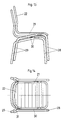
- a one-piece, seat 5 and back 6 forming shell 7 made of suitable resilient material such as plywood, plastic or metal is firmly clamped by means of fastening screws or rivets 8, such that the shell 7 as a whole is resiliently pivotable, the part of the seat 5 lying in front of the traverse essentially retains its position.
- the rear upper edge of the crossmember 2 is expediently rounded in order not to have any notch in the pivoting of the region of the shell lying behind the crossmember 2 opposite area to the rear upper edge of the traverse.
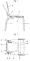
- a waist-like recess 9 is formed and from the inner end of this recess 9 to incisions 10 in the seat 5 of the shell 7 running forward in the seat direction such that when the back 6 is loaded by a person leaning against it Back 6 can pivot about a horizontal axis relative to the seat 5, which extends through the front ends of the incisions 10.
- the design corresponds to the chair according to FIGS. 1 and 2, with the exception that instead of the waist-like recess 9 provided there and the incisions 10 running in the direction of the seat, the one-piece there at the rear end of the seat 5a Shell 7a is formed a lower notch 11 such that the resulting reduction in cross-section of the shell 7a results in a greater enlargement of the seat angle opening when the back is loaded than would occur without this notch.
- the resilient adjustability between the seat 5b and the back 6b of a one-piece shell 7b is increased by a waist-like retraction 12 of the shell 7b in the rear region of the seat.
- the design of the chair corresponds to the chairs previously described.
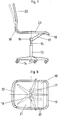
- a fork-shaped fastening element 16 is arranged, which is provided with two forwardly extending prongs 17, which have a plate-shaped traver se 18 connected, preferably welded.
- a tubular frame 19 forming a one-piece supporting structure is fixedly clamped by screws or rivets 20, a seat 21 and a back 22 between the tubular frame 19 and the like being represented in a manner not shown by corresponding filler elements, such as cross struts, cushion cushions or the like. is trained.
- the tubular frame 19 forming a one-piece support structure for the seat and back can in the same way essentially pivot as a whole about the cross member 18, like the one-piece shell in the previously described chairs, with the exception that the resilient adjustability between seat 21 and back 22 is limited to the own resilience of the tubular frame 19.
- an increase in the resilient adjustability between the seat and back could be brought about in that the tubular frame in the rear region of the seat receives a deformation, for example a flattening, which reduces its section modulus , so that there would be a corresponding enlargement of the seat angle opening when the back 22 is loaded by a seated person.
- the profile of the tubular frame 19 could be drawn in in a waist-like manner in the rear region of the seat, so that the transverse tube sections are subjected to torsional loads and thereby enlarge the seat angle opening when the seat is loaded Back 22 would result.
- a one-piece shell similar to the chairs according to FIGS. 1 to 6 could also be attached to the cross member 18.
- the design corresponds essentially to the chair according to the previously described FIGS. 7 and 8.
- the chair according to FIGS. 17 and 18 has a fork-shaped fastening element 16a an essentially horizontal U-shaped tube is formed, the legs or prongs 17a of which are attached directly to the seat 21 and additionally by means of a cross member 18a.
- a pair of rollers 35 is arranged, which have a concave outer contour to match the profile of the tubular prongs 17a (see FIG.
- a locking device not shown, which can be actuated, for example, by axial movement of the handle 37, is provided such that the rollers 35 can be locked with the axis 36 in any set position.
- the resilience of the seat 21 and back 22 forming one-piece support structure (frame 19) can be relatively large zen optimally adapted to the weight of a person using the chair.
- other suitable elements that can be adjusted in the seat direction can also be used instead of the rollers 35.
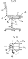
- the design of the fork-shaped fastening element 16a is the same as in the previously described chair according to FIGS. 17 and 18, with the exception of the rollers which are not provided here and are adjustable in the longitudinal direction. 19 and 20, however, a support element 38 is provided at the upper end of the rotatable telescopic part 15a, which can be extended by means of an adjusting lever 39 such that this support element 38 engages in the extended position against the underside of the rear region of the seat 21 as indicated by dashed lines in FIG. 19.
- the adjusting lever 39 is used in a known manner when it is pivoted in the vertical direction for height adjustment of the seat and back by corresponding actuation within the telescopic part 15a and by horizontal pivoting, as shown in dashed lines in FIGS. 19 and 20, for actuating the support element 38 via intermediate, Gear elements not shown in detail.
- the described support element 38 is intended to switch off the elasticity of the seat 21 as a whole if the chair is to be used for certain jobs in which springing the seat would be disadvantageous.
- the support described could element 38 can also be provided in addition to the adjustable castors 35 in the chair according to FIGS. 17 and 18.
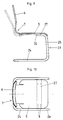
- the chair is designed with a so-called cantilever chair frame 23, i.e. a resilient tubular frame, which rests on the floor with a U-shaped base 24, the legs of the U-shaped base 24 continuing into essentially vertically directed front chair legs 25.
- the upward-pointing tubes 25 are then bent twice essentially at a right angle in order to form the supporting structure for a seat and back.
- the upward tube parts 25 are, however, only extended by a short piece 26 at the upper end after bending into the horizontal and a cross member 27 is fastened between the tube pieces 26, preferably by welding. 1 and 2, the one-piece seat and back forming shell 7 is fastened to the cross member 27 in the same way as in the embodiment according to FIGS. 1 and 2, to which reference is made in full to avoid repetition.
- a cantilever chair frame can be provided in this way with a shell-shaped seat and back construction, as is often desired and also the particularly advantageous reinforcement of the Resilient adjustability between seat and back can be achieved, as described in detail in the embodiment according to FIGS. 1 and 2. It is only to be accepted that due to the cantilever chair frame, the front end of the seat can shift on a circular path depending on the changing load due to a different seating position of the person using the chair, the center point of which lies approximately at the lower end of the chair legs 23. In cases where the chair in question is not directly associated with other furniture, such as desks or the like, this generally does not matter.
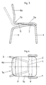
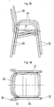
- 11 and 12 has the same chair frame as the chairs according to FIGS. 1 to 6 and has a one-piece tubular frame 19, as in the chair according to FIGS. 7 and 8. To avoid repetition, reference is therefore made to the chair according to FIGS. 7 and 8 with regard to the support structure formed by the tubular frame 19 for the seat and back.
- front chair legs 28 and rear chair legs 29 are arranged next to the seat, seen in a top view, and open downward in a V-shape, wherein each front and rear chair leg is formed by a connecting web 30 from a piece of pipe .
- an offset 31 is formed such that when chairs of the type in question are stacked one on top of the other, the front and rear chair legs of the respective upper chair come to lie in front of the front and rear chair legs of the chair underneath, as shown in FIG. 13 and 14 show.
- the seat and back construction correspond to those according to FIGS. 11 and 12 or FIGS. 7 and 8.
- front chair legs 32 and rear chair legs 33 are connected to one another by connecting webs 34, which simultaneously form armrests for the chairs in question. Otherwise, the design in terms of stackability and design of the seat and back construction corresponds to the chairs according to FIGS. 13 and 14.
- the traverse for resilient clamping of the support structure for seat and back instead of the above-described plate also consist of two spaced tubes or rods u.
- Essential and common to all embodiments is the design of the seat and back as a separate component with a one-piece support structure that is only clamped firmly at the front end of the seat, so that a Ver pivoting of the relevant one-piece seat and support structure around the front edge of the seat is possible in accordance with the load caused by the seat position of the person owning the chair.
Landscapes
- Chairs Characterized By Structure (AREA)
- Chair Legs, Seat Parts, And Backrests (AREA)
- Chairs For Special Purposes, Such As Reclining Chairs (AREA)
Priority Applications (1)
| Application Number | Priority Date | Filing Date | Title |
|---|---|---|---|
| AT86113762T ATE60201T1 (de) | 1986-04-21 | 1986-10-04 | Stuhl mit federnd verschwenkbarem sitz und ruecken. |
Applications Claiming Priority (2)
| Application Number | Priority Date | Filing Date | Title |
|---|---|---|---|
| DE19863613381 DE3613381A1 (de) | 1986-04-21 | 1986-04-21 | Stuhl mit federnd verschwenkbarem sitz und ruecken |
| DE3613381 | 1986-04-21 |
Publications (3)
| Publication Number | Publication Date |
|---|---|
| EP0242433A2 true EP0242433A2 (fr) | 1987-10-28 |
| EP0242433A3 EP0242433A3 (en) | 1988-05-04 |
| EP0242433B1 EP0242433B1 (fr) | 1991-01-23 |
Family
ID=6299137
Family Applications (1)
| Application Number | Title | Priority Date | Filing Date |
|---|---|---|---|
| EP86113762A Expired - Lifetime EP0242433B1 (fr) | 1986-04-21 | 1986-10-04 | Chaise avec siège et dossier inclinables à effet de ressort |
Country Status (6)
| Country | Link |
|---|---|
| US (1) | US4790595A (fr) |
| EP (1) | EP0242433B1 (fr) |
| AT (1) | ATE60201T1 (fr) |
| DE (3) | DE3613381A1 (fr) |
| ES (1) | ES2020914B3 (fr) |
| GR (1) | GR3001682T3 (fr) |
Cited By (8)
| Publication number | Priority date | Publication date | Assignee | Title |
|---|---|---|---|---|
| EP0382665A1 (fr) * | 1989-02-10 | 1990-08-16 | Steelcase Strafor | Mécanisme de basculement pour siège de bureau |
| EP0543206A1 (fr) * | 1991-11-02 | 1993-05-26 | Gotthard Bresch | Chaise |
| DE10009264A1 (de) * | 2000-02-26 | 2001-09-13 | Martin Woltermann | Stuhl mit Sitz, Rücken und Sitzträger bildender federnder Schale |
| RU2189771C1 (ru) * | 2001-01-29 | 2002-09-27 | Фролов Константин Владимирович | Кресло |
| FR2850013A1 (fr) * | 2003-01-17 | 2004-07-23 | Philippe Rinaldi | Chassis de fauteuil roulant amortissant les chocs |
| WO2010086187A1 (fr) * | 2009-02-02 | 2010-08-05 | Dozsa-Farkas Andras | Chaise |
| WO2016001714A1 (fr) * | 2014-06-30 | 2016-01-07 | Donati S.P.A. | Mécanisme permettant de modifier l'inclinaison du dossier par rapport à l'assise d'une chaise |
| EP3103370A1 (fr) * | 2015-06-11 | 2016-12-14 | Pro-Cord S.p.A. | Fauteuil souple |
Families Citing this family (36)
| Publication number | Priority date | Publication date | Assignee | Title |
|---|---|---|---|---|
| US4982997A (en) * | 1988-08-04 | 1991-01-08 | Snugli, Inc. | Bouncer infant carrier |
| USD344649S (en) | 1992-03-17 | 1994-03-01 | American Seating Company | Chair spine |
| USD346282S (en) | 1992-03-17 | 1994-04-26 | American Seating Company | Side chair |
| WO1993018686A1 (fr) * | 1992-03-17 | 1993-09-30 | American Seating Company | Siege d'un seul tenant dote d'une assise et d'un dossier souples |
| DE4210282C1 (fr) * | 1992-03-28 | 1993-04-01 | Martin Stoll Gmbh, 7890 Waldshut-Tiengen, De | |
| US5630648A (en) * | 1992-08-27 | 1997-05-20 | Harry C. Sweere | Dynamic posture chair |
| KR200154297Y1 (ko) * | 1997-04-03 | 1999-08-02 | 한무길 | 등받이용 탄성가동수단을 구비한 고정의자 |
| US6471293B2 (en) | 2000-11-09 | 2002-10-29 | Michigan Tube Swagers & Fabricators, Inc. | Stackable chair with flexible back support |
| US6820934B2 (en) * | 2000-11-09 | 2004-11-23 | Michigan Tube Swagers & Fabricators, Inc. | Chair having flexible back support |
| US6805412B2 (en) * | 2001-08-30 | 2004-10-19 | Burgess Furniture Ltd. | Stackable chair with flexible back |
| US6779846B2 (en) * | 2002-08-06 | 2004-08-24 | Mity-Lite, Inc. | Chair with flexible, resilient back support |
| ES2282833T3 (es) * | 2004-01-26 | 2007-10-16 | Pro-Cord S.P.A. | Silla con respaldo inclinable. |
| NO323205B1 (no) * | 2005-04-08 | 2007-01-22 | Opsvik Peter As | Stol |
| TWI458455B (zh) * | 2006-10-13 | 2014-11-01 | L & P Property Management Co | 輕便控制傾斜鎖定裝置 |
| US7753447B2 (en) * | 2006-10-13 | 2010-07-13 | L&P Property Management Company | Casual control tilt lockout |
| US7654617B2 (en) | 2008-06-06 | 2010-02-02 | Mity-Lite, Inc. | Flexible chair seat |
| US8033612B2 (en) | 2008-12-24 | 2011-10-11 | Mity-Lite, Inc. | Comfortable mesh folding chair |
| US8322787B2 (en) | 2008-12-24 | 2012-12-04 | Mity-Lite, Inc. | Clamping joint for a chair |
| US8317269B2 (en) | 2008-12-24 | 2012-11-27 | Mity-Lite, Inc. | Mesh stacking chair |
| US8454093B2 (en) | 2008-12-24 | 2013-06-04 | Mity-Lite, Inc. | Mesh chair with open-end hoop |
| USD599127S1 (en) | 2009-04-13 | 2009-09-01 | Mity-Lite, Inc. | Mesh folding chair |
| USD648554S1 (en) | 2009-11-04 | 2011-11-15 | Mity-Lite, Inc. | Mesh stacking chair |
| USD660612S1 (en) | 2010-11-16 | 2012-05-29 | Mity-Lite, Inc. | Mesh banquet chair |
| US20130187422A1 (en) * | 2012-01-24 | 2013-07-25 | Ditto Sales, Inc./Versteel | Chair having flexibility between seat and back |
| US9527413B1 (en) | 2013-11-12 | 2016-12-27 | The United States Of America As Represented By The Secretary Of The Army | Reclining seat to mitigate the effects of mine blast load on spine and lower leg injuries |
| US9173492B1 (en) * | 2014-06-06 | 2015-11-03 | Jacques Fortin | Self-reclining chair |
| US9560917B2 (en) | 2014-11-26 | 2017-02-07 | Steelcase Inc. | Recline adjustment system for chair |
| US10194750B2 (en) | 2015-04-13 | 2019-02-05 | Steelcase Inc. | Seating arrangement |
| US11259637B2 (en) | 2015-04-13 | 2022-03-01 | Steelcase Inc. | Seating arrangement |
| US10021984B2 (en) | 2015-04-13 | 2018-07-17 | Steelcase Inc. | Seating arrangement |
| US10966527B2 (en) | 2017-06-09 | 2021-04-06 | Steelcase Inc. | Seating arrangement and method of construction |
| EP3085276B1 (fr) | 2015-04-20 | 2017-08-02 | Festo AG & Co. KG | Chaise |
| USD784038S1 (en) | 2015-11-03 | 2017-04-18 | Mity-Lite, Inc. | Stacking chair |
| USD779221S1 (en) | 2015-11-03 | 2017-02-21 | Mity-Lite, Inc. | Stacking chair |
| USD779222S1 (en) | 2015-11-03 | 2017-02-21 | Mity-Lite, Inc. | Stacking chair |
| US10010178B2 (en) | 2015-11-05 | 2018-07-03 | Mity-Lite, Inc. | Stacking chair |
Family Cites Families (20)
| Publication number | Priority date | Publication date | Assignee | Title |
|---|---|---|---|---|
| DE7500152U (de) * | 1975-04-30 | Wilkhahn Wilkening + Hahne | Stuhl | |
| GB612747A (fr) * | 1900-01-01 | |||
| US1912576A (en) * | 1931-03-06 | 1933-06-06 | Levon H Gazarian | Seat construction |
| GB476315A (en) * | 1935-08-28 | 1937-12-06 | Karl Michaelis | Improvements in chairs and like furniture |
| DE683899C (de) * | 1935-11-01 | 1939-11-18 | Andreas Gaal | Sitzmoebelgestell aus federndem Werkstoff mit frei tragenden, auf Biegung beanspruchten Seitenteilen |
| FR1032914A (fr) * | 1951-02-20 | 1953-07-07 | Famva | Siège arrière, pour enfants, adaptable sur les bicyclettes vélomoteurs et motocyclettes |
| DE1099706B (de) * | 1953-09-21 | 1961-02-16 | Werner Kuester | Sitzmoebel mit auf dem Beingestell schwingbar angeordnetem, aus Sitz und Rueckenlehne bestehendem Oberteil |
| DE1118414B (de) * | 1954-08-02 | 1961-11-30 | Theo Mayer | Sitzmoebel mit einer auf einem Traggestell befestigten Sitzschale |
| DE1691799U (de) * | 1954-11-02 | 1955-01-20 | Fritz Dr Ing Drabert | Sitz mit schwingender rueckenlehne. |
| CH327658A (de) * | 1955-03-04 | 1958-02-15 | Frey Walter | Stuhl |
| AT249308B (de) * | 1964-06-23 | 1966-09-12 | Reinhold Adolf | Schwingsessel |
| DE1913042U (de) * | 1965-01-14 | 1965-04-01 | Walter Knoll & Co | Klappstuhl. |
| NL7405302A (nl) * | 1972-12-16 | 1975-10-21 | Heinz Paulisch | Zitmeubel. |
| US4047757A (en) * | 1976-05-03 | 1977-09-13 | Eames Loren W | Seating structures with flexible backs |
| EP0032839B1 (fr) * | 1980-01-21 | 1984-05-16 | Bernard Curtis Watkin | Coques pour sièges |
| DE3116459A1 (de) * | 1981-04-25 | 1982-11-11 | Sitag Sitzmöbel AG, 9430 St. Margrethen | Stuhl |
| US4529247A (en) * | 1982-04-15 | 1985-07-16 | Herman Miller, Inc. | One-piece shell chair |
| US4522444A (en) * | 1982-09-15 | 1985-06-11 | Charles Pollock | Stacking chair |
| USD289120S (en) | 1984-02-17 | 1987-04-07 | Herman Miller, Inc. | Chair shell |
| CA1184108A (fr) * | 1984-04-09 | 1985-03-19 | David W. Smith | Suspension de fauteuil basculant |
-
1986
- 1986-04-21 DE DE19863613381 patent/DE3613381A1/de active Granted
- 1986-04-21 DE DE8610855U patent/DE8610855U1/de not_active Expired
- 1986-10-04 AT AT86113762T patent/ATE60201T1/de not_active IP Right Cessation
- 1986-10-04 EP EP86113762A patent/EP0242433B1/fr not_active Expired - Lifetime
- 1986-10-04 ES ES86113762T patent/ES2020914B3/es not_active Expired - Lifetime
- 1986-10-04 DE DE8686113762T patent/DE3677205D1/de not_active Expired - Fee Related
-
1987
- 1987-04-21 US US07/040,678 patent/US4790595A/en not_active Expired - Lifetime
-
1991
- 1991-03-29 GR GR91400115T patent/GR3001682T3/el unknown
Cited By (12)
| Publication number | Priority date | Publication date | Assignee | Title |
|---|---|---|---|---|
| EP0382665A1 (fr) * | 1989-02-10 | 1990-08-16 | Steelcase Strafor | Mécanisme de basculement pour siège de bureau |
| FR2642945A1 (fr) * | 1989-02-10 | 1990-08-17 | Strafor Sa | Mecanisme de basculement pour siege de bureau |
| EP0543206A1 (fr) * | 1991-11-02 | 1993-05-26 | Gotthard Bresch | Chaise |
| DE4236834C2 (de) * | 1991-11-02 | 2002-09-05 | Gotthard Bresch | Sitzmöbel |
| DE10009264A1 (de) * | 2000-02-26 | 2001-09-13 | Martin Woltermann | Stuhl mit Sitz, Rücken und Sitzträger bildender federnder Schale |
| RU2189771C1 (ru) * | 2001-01-29 | 2002-09-27 | Фролов Константин Владимирович | Кресло |
| FR2850013A1 (fr) * | 2003-01-17 | 2004-07-23 | Philippe Rinaldi | Chassis de fauteuil roulant amortissant les chocs |
| WO2010086187A1 (fr) * | 2009-02-02 | 2010-08-05 | Dozsa-Farkas Andras | Chaise |
| WO2016001714A1 (fr) * | 2014-06-30 | 2016-01-07 | Donati S.P.A. | Mécanisme permettant de modifier l'inclinaison du dossier par rapport à l'assise d'une chaise |
| US10736424B2 (en) | 2014-06-30 | 2020-08-11 | Donati S.P.A. | Mechanism for changing the tilt of the backrest having regard to the seat of a chair |
| EP3103370A1 (fr) * | 2015-06-11 | 2016-12-14 | Pro-Cord S.p.A. | Fauteuil souple |
| US10070728B2 (en) | 2015-06-11 | 2018-09-11 | Pro-Cord S.P.A. | Flexible chair |
Also Published As
| Publication number | Publication date |
|---|---|
| EP0242433A3 (en) | 1988-05-04 |
| ES2020914B3 (es) | 1991-10-16 |
| DE3613381A1 (de) | 1987-10-22 |
| GR3001682T3 (en) | 1992-11-23 |
| ATE60201T1 (de) | 1991-02-15 |
| DE3677205D1 (de) | 1991-02-28 |
| DE8610855U1 (de) | 1988-11-24 |
| US4790595A (en) | 1988-12-13 |
| EP0242433B1 (fr) | 1991-01-23 |
| DE3613381C2 (fr) | 1988-02-25 |
Similar Documents
| Publication | Publication Date | Title |
|---|---|---|
| EP0242433A2 (fr) | Chaise avec siège et dossier inclinables à effet de ressort | |
| DE19639741C2 (de) | Sitzmöbelelement, insbesondere Polstermöbelelement, mit einer gekoppelten Rückenlehnen- und Sitzverstellung | |
| DE102012107778B4 (de) | Stuhl, insbesondere Bürostuhl | |
| DE2353341C3 (de) | Stapelbarer Kufenstuhl mit einem aus Metallrohr oder -profil gebildeten Gestell | |
| EP1252038A1 (fr) | Siege de vehicule pour avions et automobiles | |
| DE2736550C2 (fr) | ||
| DE8806924U1 (de) | Sitzmöbel | |
| DE10026531C2 (de) | Stuhl | |
| DE7630781U1 (de) | Stuhl, sessel oder dergleichen sitzmoebel | |
| EP0062724B1 (fr) | Meuble d'assise | |
| DE19622577C2 (de) | Stuhl mit einem federnden Stahlrohrgestell | |
| DE3130885A1 (de) | Aus stahlrohr aufgebautes sitzmoebel | |
| DE19526437A1 (de) | Stuhl, insbesondere Reihenstuhl | |
| DE3301209C1 (de) | Ausziehbare Couch | |
| DE1429306A1 (de) | Sitzmoebel | |
| DE10219539A1 (de) | Sitzmöbel | |
| AT404787B (de) | Sitzmöbel | |
| DE9100690U1 (de) | Sitzmöbel | |
| DE202023106950U1 (de) | Sessel mit Sitz- und Liegestellung | |
| DE1554090A1 (de) | Metall- bzw. Stahl-Sitzmoebel | |
| DE1554027C (de) | Liegestuhl | |
| AT393949B (de) | Liegensessel | |
| DE20304549U1 (de) | Umwandelbares Sitzmöbel | |
| DE202008008662U1 (de) | Sitz- oder Liegemöbel | |
| EP3586678A1 (fr) | Meuble |
Legal Events
| Date | Code | Title | Description |
|---|---|---|---|
| PUAI | Public reference made under article 153(3) epc to a published international application that has entered the european phase |
Free format text: ORIGINAL CODE: 0009012 |
|
| AK | Designated contracting states |
Kind code of ref document: A2 Designated state(s): AT BE CH DE ES FR GB GR IT LI LU NL SE |
|
| 17P | Request for examination filed |
Effective date: 19880112 |
|
| PUAL | Search report despatched |
Free format text: ORIGINAL CODE: 0009013 |
|
| AK | Designated contracting states |
Kind code of ref document: A3 Designated state(s): AT BE CH DE ES FR GB GR IT LI LU NL SE |
|
| 17Q | First examination report despatched |
Effective date: 19890927 |
|
| GRAA | (expected) grant |
Free format text: ORIGINAL CODE: 0009210 |
|
| AK | Designated contracting states |
Kind code of ref document: B1 Designated state(s): AT BE CH DE ES FR GB GR IT LI LU NL SE |
|
| REF | Corresponds to: |
Ref document number: 60201 Country of ref document: AT Date of ref document: 19910215 Kind code of ref document: T |
|
| REF | Corresponds to: |
Ref document number: 3677205 Country of ref document: DE Date of ref document: 19910228 |
|
| ITF | It: translation for a ep patent filed | ||
| ET | Fr: translation filed | ||
| GBT | Gb: translation of ep patent filed (gb section 77(6)(a)/1977) | ||
| PGFP | Annual fee paid to national office [announced via postgrant information from national office to epo] |
Ref country code: SE Payment date: 19911001 Year of fee payment: 6 |
|
| PGFP | Annual fee paid to national office [announced via postgrant information from national office to epo] |
Ref country code: GB Payment date: 19911002 Year of fee payment: 6 |
|
| PGFP | Annual fee paid to national office [announced via postgrant information from national office to epo] |
Ref country code: CH Payment date: 19911007 Year of fee payment: 6 |
|
| PGFP | Annual fee paid to national office [announced via postgrant information from national office to epo] |
Ref country code: GR Payment date: 19911011 Year of fee payment: 6 |
|
| PGFP | Annual fee paid to national office [announced via postgrant information from national office to epo] |
Ref country code: ES Payment date: 19911014 Year of fee payment: 6 |
|
| PGFP | Annual fee paid to national office [announced via postgrant information from national office to epo] |
Ref country code: FR Payment date: 19911018 Year of fee payment: 6 |
|
| PGFP | Annual fee paid to national office [announced via postgrant information from national office to epo] |
Ref country code: LU Payment date: 19911024 Year of fee payment: 6 |
|
| PGFP | Annual fee paid to national office [announced via postgrant information from national office to epo] |
Ref country code: AT Payment date: 19911028 Year of fee payment: 6 |
|
| PGFP | Annual fee paid to national office [announced via postgrant information from national office to epo] |
Ref country code: NL Payment date: 19911031 Year of fee payment: 6 |
|
| PGFP | Annual fee paid to national office [announced via postgrant information from national office to epo] |
Ref country code: BE Payment date: 19911104 Year of fee payment: 6 |
|
| PLBE | No opposition filed within time limit |
Free format text: ORIGINAL CODE: 0009261 |
|
| STAA | Information on the status of an ep patent application or granted ep patent |
Free format text: STATUS: NO OPPOSITION FILED WITHIN TIME LIMIT |
|
| 26N | No opposition filed | ||
| EPTA | Lu: last paid annual fee | ||
| REG | Reference to a national code |
Ref country code: GR Ref legal event code: FG4A Free format text: 3001682 |
|
| PG25 | Lapsed in a contracting state [announced via postgrant information from national office to epo] |
Ref country code: LU Free format text: LAPSE BECAUSE OF NON-PAYMENT OF DUE FEES Effective date: 19921004 Ref country code: GB Effective date: 19921004 Ref country code: AT Effective date: 19921004 |
|
| PG25 | Lapsed in a contracting state [announced via postgrant information from national office to epo] |
Ref country code: SE Effective date: 19921005 Ref country code: ES Free format text: LAPSE BECAUSE OF EXPIRATION OF PROTECTION Effective date: 19921005 |
|
| PG25 | Lapsed in a contracting state [announced via postgrant information from national office to epo] |
Ref country code: LI Effective date: 19921031 Ref country code: CH Effective date: 19921031 Ref country code: BE Effective date: 19921031 |
|
| BERE | Be: lapsed |
Owner name: MAUSER WALDECK A.G. Effective date: 19921031 |
|
| PG25 | Lapsed in a contracting state [announced via postgrant information from national office to epo] |
Ref country code: GR Free format text: THE PATENT HAS BEEN ANNULLED BY A DECISION OF A NATIONAL AUTHORITY Effective date: 19930430 |
|
| PG25 | Lapsed in a contracting state [announced via postgrant information from national office to epo] |
Ref country code: NL Effective date: 19930501 |
|
| GBPC | Gb: european patent ceased through non-payment of renewal fee |
Effective date: 19921004 |
|
| NLV4 | Nl: lapsed or anulled due to non-payment of the annual fee | ||
| PG25 | Lapsed in a contracting state [announced via postgrant information from national office to epo] |
Ref country code: FR Effective date: 19930630 |
|
| REG | Reference to a national code |
Ref country code: CH Ref legal event code: PL |
|
| REG | Reference to a national code |
Ref country code: FR Ref legal event code: ST |
|
| REG | Reference to a national code |
Ref country code: GR Ref legal event code: MM2A Free format text: 3001682 |
|
| EUG | Se: european patent has lapsed |
Ref document number: 86113762.8 Effective date: 19930510 |
|
| PGFP | Annual fee paid to national office [announced via postgrant information from national office to epo] |
Ref country code: DE Payment date: 19950801 Year of fee payment: 10 |
|
| PG25 | Lapsed in a contracting state [announced via postgrant information from national office to epo] |
Ref country code: DE Effective date: 19970701 |
|
| REG | Reference to a national code |
Ref country code: ES Ref legal event code: FD2A Effective date: 19990601 |
|
| PG25 | Lapsed in a contracting state [announced via postgrant information from national office to epo] |
Ref country code: IT Free format text: LAPSE BECAUSE OF NON-PAYMENT OF DUE FEES;WARNING: LAPSES OF ITALIAN PATENTS WITH EFFECTIVE DATE BEFORE 2007 MAY HAVE OCCURRED AT ANY TIME BEFORE 2007. THE CORRECT EFFECTIVE DATE MAY BE DIFFERENT FROM THE ONE RECORDED. Effective date: 20051004 |