EP0242924A1 - Dispositif de reliure pour une pile de feuilles - Google Patents
Dispositif de reliure pour une pile de feuilles Download PDFInfo
- Publication number
- EP0242924A1 EP0242924A1 EP87200735A EP87200735A EP0242924A1 EP 0242924 A1 EP0242924 A1 EP 0242924A1 EP 87200735 A EP87200735 A EP 87200735A EP 87200735 A EP87200735 A EP 87200735A EP 0242924 A1 EP0242924 A1 EP 0242924A1
- Authority
- EP
- European Patent Office
- Prior art keywords
- cassette
- adhesive tape
- pile
- paper
- support
- Prior art date
- Legal status (The legal status is an assumption and is not a legal conclusion. Google has not performed a legal analysis and makes no representation as to the accuracy of the status listed.)
- Withdrawn
Links
- 239000002390 adhesive tape Substances 0.000 claims abstract description 47
- 239000003292 glue Substances 0.000 claims description 4
- 229920001296 polysiloxane Polymers 0.000 claims description 4
- 239000000853 adhesive Substances 0.000 claims description 3
- 230000001070 adhesive effect Effects 0.000 claims description 3
- 238000000151 deposition Methods 0.000 description 3
- 239000000969 carrier Substances 0.000 description 2
- 230000001154 acute effect Effects 0.000 description 1
- 238000010276 construction Methods 0.000 description 1
- 238000010586 diagram Methods 0.000 description 1
- 239000004816 latex Substances 0.000 description 1
- 229920000126 latex Polymers 0.000 description 1
- 238000004519 manufacturing process Methods 0.000 description 1
- 239000000463 material Substances 0.000 description 1
- 239000012858 resilient material Substances 0.000 description 1
- 229920002994 synthetic fiber Polymers 0.000 description 1
Images


Classifications
-
- B—PERFORMING OPERATIONS; TRANSPORTING
- B42—BOOKBINDING; ALBUMS; FILES; SPECIAL PRINTED MATTER
- B42C—BOOKBINDING
- B42C9/00—Applying glue or adhesive peculiar to bookbinding
- B42C9/0056—Applying glue or adhesive peculiar to bookbinding applying tape or covers precoated with adhesive to a stack of sheets
- B42C9/0062—Applying glue or adhesive peculiar to bookbinding applying tape or covers precoated with adhesive to a stack of sheets the tape being fed from a roller
- B42C9/0068—Applying glue or adhesive peculiar to bookbinding applying tape or covers precoated with adhesive to a stack of sheets the tape being fed from a roller on a single stack of sheets
-
- Y—GENERAL TAGGING OF NEW TECHNOLOGICAL DEVELOPMENTS; GENERAL TAGGING OF CROSS-SECTIONAL TECHNOLOGIES SPANNING OVER SEVERAL SECTIONS OF THE IPC; TECHNICAL SUBJECTS COVERED BY FORMER USPC CROSS-REFERENCE ART COLLECTIONS [XRACs] AND DIGESTS
- Y10—TECHNICAL SUBJECTS COVERED BY FORMER USPC
- Y10S—TECHNICAL SUBJECTS COVERED BY FORMER USPC CROSS-REFERENCE ART COLLECTIONS [XRACs] AND DIGESTS
- Y10S412/00—Bookbinding: process and apparatus
- Y10S412/902—Heating and pressing
Definitions
- the invention has reference to an apparatus for binding a pile of paper by folding an adhesive tape around the back of the pile and pressing the tape around it, comprising a table supporting the pile of paper and an adhesive tape emitting device which are movable with respect to one another.
- Such a binding apparatus is known from the German Offenlegungsschrift 25 28 111.
- the adhesive tape emitting device is mounted stationarily and the pile of paper is moved on a table, constructed in the form of a slide, with respect to the adhesive tape emitting device.
- the adhesive tape emitting device comprises a support for rotatably supporting a roll of adhesive tape, said support being provided with an arm to enable it to rotate about a substantially vertical axis with respect to a pressure rail and to move parallely to said pressure rail which is able to fix the pile of paper with respect to the table.
- a carriage that supports the adhesive tape emitting device can be guided through the pressure rail itself or through a guiding groove provided beneath the pressure rail at the table.
- the support may prefereably rotate about an axis that is horizontal with respect to the pressure rail or the guiding groove. This makes it easier to provide a new adhesive tape.
- the adhesive tape consists of a covering strip with a silicone layer and a support covered with glue at the side facing the covering strip
- the adhesive tape is located in a cassette that can be non-rotatably connected to the support constructed as cassette support, said cassette, at the side that is to be pressed against the back of the pile of paper, preferably being provided with an emitting rod, a first pressure roller and with a discharge roller having a counter-roller which are juxtaposed substantially perpendicularly to the direction of travel and between which only the covering strip passes,while a pressing mechanism is provided to fold the carrier around the back and to press against it.
- the pressure rail may be rotatable about a horizontal axis that lies beyond the table to such an extent that the first pressure roller may reach the beginning of the back that is to be glued, and, furthermore, the table may be provided with a projection in the extension of the back that is to be glued, so that the first pressure roller may reach the end of the back that is to be glued, while the discharge roller may then still be rotated.
- the discharge roller has a rough surface so that the back may also be roughened, said discharge roller being drivable by a wheel running over the guiding groove. As a result the binding results are improved.
- the pressing mechanism may comprise a pair of resilient lips that are attached to the cassette.
- a cassette that is apparently meant to be used for a binding apparatus comprises, as its most essential characteristic, a trough-shaped housing in which a filling cassette fits that is provided with a core with a roll of adhesive tape, which filling cassette can be fixed into said housing by means of a clicking connection and a back adapted to the outward appearance of the cassette support, the bottom of the housing being provided with at least one hole to be able to remove the filling cassette from said housing.
- the housing In its upper surface the housing may be provided with a groove to allow the adhesive tape from another filling cassette to pass.
- the glue-covered carrier of the adhesive tape may be pre-cut to match the length of the back that is to be glued.
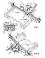
- the apparatus depicted in the drawing substantially comprises a table 1 with a front and a rear edge 2 and 3, respectively, a recess 4 in one of the longitudinal edges and a long leg 5 as well as a short leg 6 at the other longitudinal edge.
- the posts 7 and 8 are meant to cooperate with a pressure rail 9 over which an adhesive tape emitting device 10 can move.
- edges 2 and 3 extend along the cross edges and one of the longitudinal edges of the table 1 till the recess 4 in such a way that a suitable depositing surface is provided for the pile of papers that is to bound, and said pile can also easily be removed from it after binding.
- a suitable depositing surface is provided for the pile of papers that is to bound, and said pile can also easily be removed from it after binding.
- the inner walls of the edges 2, 3 may be provided with indications as to the height of the pile that has to be bound and these indications should correspond with the height adjustment of the pressure rail 9 with respect to the adjusting post 7 in order to attain good binding results.
- no edges are present, but a swing-aside pressure baffle that is supported in such a way that extra pressure is exerted on the pressure rail when the baffle is swung aside, is present however.
- a fork 11 is provided which has a width that is adapted to the cross section of the adjusting post 7 in such a way that it can slide over the post when it is turned up around a horizontal axis 12 that extends through one of the outer ends of the pressure rail 9.
- a plug 13 provided at one of the ends of the pressure rail 9, presses against the adjusting post 7 so that the pressure rail 9 can then not slide over the adjusting post.
- the plug 13 may be made of synthetic material.
- the other outer end of the pressure rail 9 has a provision for rotatably accommodating an eccentric roll 14 with a handle 15 with the aid of which the pressure rail 9 can be anchored to the clamping post 8 after the pile of paper that has to be bound has been pressed against the table 1 by the pressure rail 9.
- the posts 7 and 8 are illustrated with a square cross section here, but they may also have another polygonal cross section.
- the base of the table 1 and the position of the pressure rail 9 have now been selected in such a way that the areas adjacent to the back of the pile of paper that has to be bound are free to receive the edges of adhesive tape that is yet to be discussed, said edges being folded around said areas.
- the adhesive tape emitting device 10 comprises a plate-shaped cassette support 16 to which, at the bottom side, a cassette 17 can be attached, and which is movably mounted on the pressure rail 9.
- the cassette support 16 comprises a substantially triangular portion 18 that lies above the cassette 17, and an oblong portion 19 that lies above the pressure rail 9.
- the oblong portion is connected to a sheet 21 (fig. 3) via a horizontal pivot 20, which sheet is, itself, connected around a vertical pin 22 to a cylindrical carriage 23 that contains a plurality of, preferably three wheels 24 that can travel over the pressure rail 9 with a substantially I-shaped cross section.
- This I-profile is constructed more heavily at the bottom side than at the upper side.
- the whole of the parts 21 - 24 is indicated as the set of rollers 25 in figures 2 and 3.
- the cassette support 16 Adjacent to the triangular portion 18 the cassette support 16 has a bent-over edge 26 which can serve as a guide when the cassette 17 is put in position and is also connected to an arm 27 to enable the cassette support to be operated.
- the parts 16, 18 - 20, 26 and 27 may be in a single piece.
- a pin 29 (figure 6) provided with a knob 28, which pin extends through a hole in the cassette support 16 in a manner that is yet to be elucidated.
- the knob 28 By removing the knob 28 the cassette 17 may be released from the cassette support 16. With the aid of the arm 27 that is attached to the cassette support 16 the cassette 17 may be pressed against the back of the pile of paper and moved along it.
- a roll 30 with adhesive tape 31 is visible in the cassette 17 around the (non-visible) pin with knob 28.
- the adhesive tape consists of a covering strip 32 with a silicone layer and a carrier 33 that is covered with glue at the side facing the covering strip 32 or is made adhesive in some other way.
- the carrier 33 is usually called "tape”.
- the covering strip 32 extends around an emitting rod 34 to the nip of a discharge roller 35 and a reaction-roller 36.
- the carrier 33 projects between the emitting rod 34 and a first pressure roller 37 outwards, out of the cassette 17 and, with its adhesive side, it reaches the back of the pile of paper that is to be bound when the adhesive tape emitting device 10 is pressed against it with the aid of the arm 27 (figure 1). With the same arm the adhesive tape emitting device is then moved from left to right in figure 2.
- the discharge roller is rotated on account of the fact that the adhesive tape emitting device is moved along the back of the pile of paper and when this takes place the covering strip 32 is discharged.
- the discharge roller 35 also serves to roughen the back, which will result in a better adhesion of the carrier 33 to the back.
- FIG 5 a detail is illustrated of the corner of table 1 at the location of the rear edge 3 and the short leg 6 with clamping post 8 and with the eccentric roll 14 cooperating with it. From this figure it appears that a projection 35 is provided next to the short leg 5, said projection lying in the extension of the back that is to be bound, for the discharge roller 35 must keep on rotating until the discharge rod 34 has reached the end of the back.
- a dotted line indicates the position in which the carrier 33 is finally folded around the back of the pile of paper that is to be bound.
- Figure 6 shows the principle of folding the carrier 33 around the back and pressing against it. Parts that have already been discussed are the cassette support 16, the cassette 17, the knob 28 with pin 29, as well as the emitting rod 34, the discharge roller 35 and the first pressure roller 37. On a shaft 30 a second pressure roller 39 and a pair of washers 40 are mounted that are pressed together by means of springs 41.
- the washers 40 are preferably made of a resilient material, and the spring constant of the springs 41 is attuned to the material characteristics of the washers 40 and the thickness of the piles of paper that are to be bound,in such a way that the carrier 33 is always folded neatly around the back and pressed against it, irrespective of the number of sheets of paper of the pile that is to be bound, at least within the limits indicated below for various widths of adhesive tape.
- the upper washer 40 has a bore that is adapted to the diameter of the second pressure roller 39.
- the second pressure roller 39 is biassed by a pressure spring 51 that is stronger than the springs 41 and ensures that the upper washer 40 always stands below the pressure rail in more or less the same position, for the height position of the cassette support of the adhesive tape emitting device is constant for all widths of adhesive tape.
- the bottom washer 40 has a bore that is adapted to the diameter of the shaft 50.
- the adhesive tapes preferably consist of a covering strip on which successively precut carriers of a length of 29.7 mm, for instance, are placed, so that sheets of paper of the standard format A4 may be handled by the invented apparatus.
- Other dimensions are possible too, however.
- the invented apparatus and the corresponding cassettes are especially meant for use on a relatively small scale, including the binding of reports by co-called copying-shops, for instance.
- copying-shops for instance.
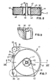
- FIG. 7 - 9 further details are given of the cassette 17 for smale-scale use.
- This cassette appears to be built-up of a trough-shaped housing 42 with a housing bottom 43 from which the pin 29 protrudes that, at its upper end, is provided with helical thread to cooperate with the knob 28 (figures 1, 2, 4 and 6).
- a circular filling cassette 44 fits into the trough-shaped housing 42, said filling cassette being provided with a hollow core 45 that can be slid around the pin 29 and around which the roll 30 of adhesive tape is wound.
- the housing has horizontal upper surface portions containing the upper pivots for the rolls 35 - 37 and 39.
- the bore of the core 45 is conically widened and there it can cooperate with lips 46, protruding obliquely from the bottom 43 of the housing, said lips ensuring that the roll 30 does not slide away when it is half-empty and the filling cassette 44 is separated from the cassette 17, for then the pin no longer projects into the bore of the core 45.
- the cassette 17 and the filling cassette 44 have a ridge 47, the course of which matches the outward appearance of the cassette support 16 and therefore serves to prevent rotation of the cassette with respect to the cassette support.
- the filling cassette 44 has a clicking groove which can cooperate with a clicking edge - directed inwards - of the housing 42, in the manner depicted in figure 9.
- the filling cassette consists of an upper- and a lower half which can be attached to one another after the cassette has been filled with the roll 30 as illustrated in figure 9.
- the bottom 43 of the housing is provided with a plurality of holes 48 with dimensions that are large enough to allow fingers to pass, so that an empty filling cassette 44 may be pressed out of the housing 42.
- the knob 28 must first have been removed.
- the adhesive tape 31 projecting from it is divided into a covering strip 32, which is placed around the emitting rod 34 and between the rollers 35 and 36 of the cassette 17, and a carrier 33 that, via a groove 39 in the upper surface of the housing 42, is led around the first guiding roller 37 of the cassette, ready to bind a pile of paper.
- the adhesive tape emitting device is moved so far in the direction of the adjusting post 7 that the carrier 33 is located at the beginning of the back of the pile of paper that is to be bound.
- the discharge roller 35 and the first pressure roller 37 of the adhesive tape emitting device are pressed against the back and said device is then moved in the direction of the clamping post 8 along the back.
- the second pressure roller takes over the task of the first pressure roller 37 and tilts the adhesive tape emitting device over through angle ⁇ , as illustrated in figure 4.
- the carrier 33 may be cut (if it is not precut) and the last piece of the provided carrier may be folded by the washer 40, after which the adhesive tape emitting device may be turned away from the back.
- a cassette 17 ⁇ is illustrated for an adhesive tape that consists of a carrier of paper impregnated with latex, said carrier being covered with glue at its bottom side and being provided with a silicone layer at the upper side.
- the pressing mechanism here consists of two resilient lips 52 and 53, the upper lip 52 of which can deflect over a larger distance.
- the discharge roller 35 is driven by a wheel 54 that runs over a guiding groove (not illustrated).
- a sliding blade 55 is present in this embodiment, to be able to cut the adhesive tape.
Landscapes
- Folding Of Thin Sheet-Like Materials, Special Discharging Devices, And Others (AREA)
Applications Claiming Priority (2)
| Application Number | Priority Date | Filing Date | Title |
|---|---|---|---|
| NL8600986A NL8600986A (nl) | 1986-04-18 | 1986-04-18 | Apparaat voor het inbinden van een stapel papier. |
| NL8600986 | 1986-04-18 |
Publications (1)
| Publication Number | Publication Date |
|---|---|
| EP0242924A1 true EP0242924A1 (fr) | 1987-10-28 |
Family
ID=19847896
Family Applications (1)
| Application Number | Title | Priority Date | Filing Date |
|---|---|---|---|
| EP87200735A Withdrawn EP0242924A1 (fr) | 1986-04-18 | 1987-04-16 | Dispositif de reliure pour une pile de feuilles |
Country Status (3)
| Country | Link |
|---|---|
| US (1) | US4861212A (fr) |
| EP (1) | EP0242924A1 (fr) |
| NL (1) | NL8600986A (fr) |
Cited By (2)
| Publication number | Priority date | Publication date | Assignee | Title |
|---|---|---|---|---|
| US9319942B2 (en) | 2009-05-18 | 2016-04-19 | Nokia Technologies Oy | Systems, methods, and apparatuses for facilitating a circuit switched connection |
| DE102018109068A1 (de) * | 2018-04-17 | 2019-10-17 | Bundesdruckerei Gmbh | Verfahren und Vorrichtung zum Aufbringen eines von einem streifenförmigen Klebefilm separierten Klebefilmabschnitts auf eine Buchdecke |
Families Citing this family (6)
| Publication number | Priority date | Publication date | Assignee | Title |
|---|---|---|---|---|
| US5039268A (en) * | 1989-05-12 | 1991-08-13 | Dennison Manufacturing Company | Sheet binding apparatus and binders for use therewith |
| US5180153A (en) * | 1991-03-07 | 1993-01-19 | Harold W. Gegenheimer | Method and apparatus for maintaining confidential printed-sheet output |
| US5632853A (en) * | 1995-04-26 | 1997-05-27 | International Binding Corporation | Adhesive cartridge for a desktop book binder |
| ATE235380T1 (de) | 1997-12-01 | 2003-04-15 | Economic Strategies Inc | Zum binden vorbereitetes blatt, und klebeband zum binden einzelner blätter |
| US6030166A (en) * | 1999-05-24 | 2000-02-29 | Tekpak Corporation | Mechanism for loading a lashing tape of a binding machine |
| JP6665684B2 (ja) * | 2016-05-25 | 2020-03-13 | ノーリツプレシジョン株式会社 | 製本機 |
Citations (4)
| Publication number | Priority date | Publication date | Assignee | Title |
|---|---|---|---|---|
| DE2456341A1 (de) * | 1974-11-28 | 1976-08-12 | Xerox Corp | Buchbindevorrichtung |
| DE2528111A1 (de) * | 1975-06-24 | 1977-04-21 | Koenig Kg Claus | Vorrichtung zum faelzeln eines blocks aus papierblaettern |
| EP0095599A2 (fr) * | 1982-06-02 | 1983-12-07 | Claus Koenig KG | Dispositif pour transférer un morceau de bande adhésive à un appareil d'encollage du dos d'un bloc de livre ou analogue |
| GB2125735A (en) * | 1982-08-03 | 1984-03-14 | Stanley Charles Rudd | Book finishing |
Family Cites Families (5)
| Publication number | Priority date | Publication date | Assignee | Title |
|---|---|---|---|---|
| US3223436A (en) * | 1963-04-22 | 1965-12-14 | Hollis V Becker | Method of binding books and product thereof |
| DE1280213B (de) * | 1964-10-24 | 1968-10-17 | Alpina Werke Bovensiepen K G | Vorrichtung zum Binden von Schriftgut unter Verwendung einer thermoplastischen Folie |
| US3804694A (en) * | 1972-03-20 | 1974-04-16 | Brackett Stripping Machine Co | Binding apparatus |
| CH540816A (de) * | 1972-05-08 | 1973-08-31 | Grapha Holding Ag | Verfahren zum Verpacken einer Broschüre oder Zeitschrift |
| US4662770A (en) * | 1984-11-30 | 1987-05-05 | Carstens Health Industries, Inc. | Pressure sensitive reinforcement tape for loose leaf sheet |
-
1986
- 1986-04-18 NL NL8600986A patent/NL8600986A/nl not_active Application Discontinuation
-
1987
- 1987-04-16 EP EP87200735A patent/EP0242924A1/fr not_active Withdrawn
-
1988
- 1988-05-16 US US07/195,477 patent/US4861212A/en not_active Expired - Lifetime
Patent Citations (4)
| Publication number | Priority date | Publication date | Assignee | Title |
|---|---|---|---|---|
| DE2456341A1 (de) * | 1974-11-28 | 1976-08-12 | Xerox Corp | Buchbindevorrichtung |
| DE2528111A1 (de) * | 1975-06-24 | 1977-04-21 | Koenig Kg Claus | Vorrichtung zum faelzeln eines blocks aus papierblaettern |
| EP0095599A2 (fr) * | 1982-06-02 | 1983-12-07 | Claus Koenig KG | Dispositif pour transférer un morceau de bande adhésive à un appareil d'encollage du dos d'un bloc de livre ou analogue |
| GB2125735A (en) * | 1982-08-03 | 1984-03-14 | Stanley Charles Rudd | Book finishing |
Cited By (3)
| Publication number | Priority date | Publication date | Assignee | Title |
|---|---|---|---|---|
| US9319942B2 (en) | 2009-05-18 | 2016-04-19 | Nokia Technologies Oy | Systems, methods, and apparatuses for facilitating a circuit switched connection |
| DE102018109068A1 (de) * | 2018-04-17 | 2019-10-17 | Bundesdruckerei Gmbh | Verfahren und Vorrichtung zum Aufbringen eines von einem streifenförmigen Klebefilm separierten Klebefilmabschnitts auf eine Buchdecke |
| DE102018109068B4 (de) * | 2018-04-17 | 2025-08-14 | Bundesdruckerei Gmbh | Verfahren und Vorrichtung zum Aufbringen eines von einem streifenförmigen Klebefilm separierten Klebefilmabschnitts auf eine Buchdecke |
Also Published As
| Publication number | Publication date |
|---|---|
| NL8600986A (nl) | 1987-11-16 |
| US4861212A (en) | 1989-08-29 |
Similar Documents
| Publication | Publication Date | Title |
|---|---|---|
| EP0242924A1 (fr) | Dispositif de reliure pour une pile de feuilles | |
| JP3043401B2 (ja) | 乱雑化防止装置を有する文書出力装置 | |
| CA2712134A1 (fr) | Procede de formation d'agenda et appareil pour celui-ci | |
| US6547881B1 (en) | Paper dispenser | |
| KR100753373B1 (ko) | 시트 재료를 기재에 인가하기 위한 어플리케이터 및 방법 | |
| US2107603A (en) | Roll tape container | |
| CA2737844A1 (fr) | Systeme de distribution de billets | |
| US5044857A (en) | Casing-in machine | |
| US3804694A (en) | Binding apparatus | |
| US4364553A (en) | Sheet stacking apparatus | |
| NL8603234A (nl) | Afgifte-inrichting voor servetten. | |
| US4094498A (en) | Separator | |
| CA1138838A (fr) | Distributeur de feuillets et de papier collant | |
| CA2102696C (fr) | Appareil pour separer une trame en pieces, empiler ces pieces et, selon le cas, apres les avoir pliees | |
| JPH07506077A (ja) | フィルム及びラップディスペンサ | |
| EP0929492B1 (fr) | Structure de rouleau de bande utilisee dans la confection d'onglet de bords de marge pour feuilles | |
| CN217256619U (zh) | 一种印刷品裁切回收装置 | |
| US2321055A (en) | Window shade machine | |
| US3323791A (en) | Collator with friction collector | |
| US4307829A (en) | Paper cutting apparatus | |
| CN223820613U (zh) | 一种广告设计用广告纸裁切装置 | |
| US4286488A (en) | Dispensing apparatus for rolled sheet material | |
| GB2149762A (en) | Tissue dispenser | |
| US4753396A (en) | Viewer for auditing cash register tapes | |
| JPH0636023Y2 (ja) | メモペーパー送出器 |
Legal Events
| Date | Code | Title | Description |
|---|---|---|---|
| PUAI | Public reference made under article 153(3) epc to a published international application that has entered the european phase |
Free format text: ORIGINAL CODE: 0009012 |
|
| 17P | Request for examination filed |
Effective date: 19870729 |
|
| AK | Designated contracting states |
Kind code of ref document: A1 Designated state(s): BE DE FR GB IT |
|
| 17Q | First examination report despatched |
Effective date: 19890313 |
|
| STAA | Information on the status of an ep patent application or granted ep patent |
Free format text: STATUS: THE APPLICATION IS DEEMED TO BE WITHDRAWN |
|
| 18D | Application deemed to be withdrawn |
Effective date: 19901015 |
|
| RIN1 | Information on inventor provided before grant (corrected) |
Inventor name: CORDIA, ANNE-LOUISE |