EP0242996A2 - Förderarm für Plättchen - Google Patents
Förderarm für Plättchen Download PDFInfo
- Publication number
- EP0242996A2 EP0242996A2 EP87302482A EP87302482A EP0242996A2 EP 0242996 A2 EP0242996 A2 EP 0242996A2 EP 87302482 A EP87302482 A EP 87302482A EP 87302482 A EP87302482 A EP 87302482A EP 0242996 A2 EP0242996 A2 EP 0242996A2
- Authority
- EP
- European Patent Office
- Prior art keywords
- wafer
- arm
- piece
- proximal
- extensor
- Prior art date
- Legal status (The legal status is an assumption and is not a legal conclusion. Google has not performed a legal analysis and makes no representation as to the accuracy of the status listed.)
- Withdrawn
Links
Images


Classifications
-
- H—ELECTRICITY
- H10—SEMICONDUCTOR DEVICES; ELECTRIC SOLID-STATE DEVICES NOT OTHERWISE PROVIDED FOR
- H10P—GENERIC PROCESSES OR APPARATUS FOR THE MANUFACTURE OR TREATMENT OF DEVICES COVERED BY CLASS H10
- H10P72/00—Handling or holding of wafers, substrates or devices during manufacture or treatment thereof
- H10P72/04—Apparatus for manufacture or treatment
- H10P72/0441—Apparatus for sealing, encapsulating, glassing, decapsulating or the like
-
- H—ELECTRICITY
- H10—SEMICONDUCTOR DEVICES; ELECTRIC SOLID-STATE DEVICES NOT OTHERWISE PROVIDED FOR
- H10P—GENERIC PROCESSES OR APPARATUS FOR THE MANUFACTURE OR TREATMENT OF DEVICES COVERED BY CLASS H10
- H10P72/00—Handling or holding of wafers, substrates or devices during manufacture or treatment thereof
- H10P72/30—Handling or holding of wafers, substrates or devices during manufacture or treatment thereof for conveying, e.g. between different workstations
- H10P72/33—Handling or holding of wafers, substrates or devices during manufacture or treatment thereof for conveying, e.g. between different workstations into and out of processing chamber
- H10P72/3304—Handling or holding of wafers, substrates or devices during manufacture or treatment thereof for conveying, e.g. between different workstations into and out of processing chamber characterised by movements or sequence of movements of transfer devices
-
- H—ELECTRICITY
- H10—SEMICONDUCTOR DEVICES; ELECTRIC SOLID-STATE DEVICES NOT OTHERWISE PROVIDED FOR
- H10P—GENERIC PROCESSES OR APPARATUS FOR THE MANUFACTURE OR TREATMENT OF DEVICES COVERED BY CLASS H10
- H10P72/00—Handling or holding of wafers, substrates or devices during manufacture or treatment thereof
- H10P72/30—Handling or holding of wafers, substrates or devices during manufacture or treatment thereof for conveying, e.g. between different workstations
- H10P72/33—Handling or holding of wafers, substrates or devices during manufacture or treatment thereof for conveying, e.g. between different workstations into and out of processing chamber
- H10P72/3306—Horizontal transfer of a single workpiece
Definitions
- This invention pertains to a wafer handling arm operated from two concentric shafts such that the tip of the arm can be rotated and extended in a single plane in a complex trajectory.
- Isolation means must be provided between chambers and means for moving wafers must be provided compatible with the isolation. All this must be provided in a way which generates a minimum of particulates which might contaminate the wafer.
- isolation is provided by valves and wafer movement is handled by an independent mechanism.
- US-A-4,433,95l and US-A-4,483,654 disclose a transfer mechanism in an isolation chamber. Separate valves are required on either side of the isolation chamber The transfer mechanism within the isolation chamber is complex and prone to particulate generation problems.
- US-A-4,533,069 and EP-A-l60,305 disclose a wafer handling arm having four trapezoidally-shaped sides.
- the side arms extend sideways as the arm is shortened, thereby requiring a large opening in which to operate the arm.
- EP-A-l52,555 discloses a two-piece arm driven by gears and pulleys which inherently generate particulates.
- US-A-3,92l,788 discloses a wafer handling mechanism on a slide mechanism.
- the slide mechanism is inherently present in the work area and subject to generation of particulates.
- a wafer handling arm is formed of a proximal extensor piece, a distal extensor piece, a proximal support arm, and a distal support arm.
- the distal extensor piece and the proximal support arm are pivotally attached to the distal support arm at two different points.
- the proximal extensor piece is pivotally attached to the distal extensor piece.
- the proximal extensor piece and the proximal support arm are each connected fixedly to a one of a pair of concentric shafts. Rotating one shaft rotates the entire arm.
- the distal support arm is formed as a flat blade with cushions to support the wafer. Because the two shafts can be rotated independently, the motion of the tip of the arm which bears the wafer can be programmed to move in a complex non-linear trajectory. By making the proximal extensor piece much shorter than the other three pieces, the arm can be made to fold compactly and store in a small space.
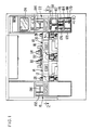
- FIG. l a front view in partial section of a wafer processing system.
- An input loadlock l0 is used to load a cassette of wafers.
- An isolation valve l2 is located in the path of the wafer before the first processing chamber l4.
- a second isolation valve l6 is located in the path of the wafer before the second processing chamber l8.
- a third isolation valve 20 is located between the second processing chamber l8 and the output loadlock 22.
- a computer 24 with controls through a keyboard and touch-screen is used to control operation of the system.
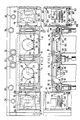
- FIG. 2 shows a partial section through the line 2-2 of the system of FIG. l and FIG. 3 shows a partial section of the same system through the line 3-3.
- wafer handling arms 40, 42, 44 are shown in solid lines in the stored position.
- Wafer handling arm 40 is shown in dotted lines 46 taking a wafer 48 from a cassette 50.
- Wafer handling arm 40 is shown in dotted lines 52 placing the wafer 48 in the processing chamber l4.
- wafer handling arm 42 is shown in dotted lines 54 as it picks up the wafer in the first processing chamber l4 and in dotted lines 56 as it places the wafer in the second processing chamber l8.
- Wafer handling arm 44 is shown in dotted lines 58 taking a wafer from the second processing chamber l8 and in dotted lines 60 placing the wafer in the output cassette 62.
- the wafer handling arms 40, 44 are shown in the stored position inside valves l2, 20 with the valve wedge 64, 66 seated in the closed position.
- the wafer handling arm in the valve l6 is shown in solid lines 68 in the first processing chamber l4 and in dotted lines 56 in the second processing chamber l8.
- the valve wedge 69 of the valve l6 is shown in the open position, showing that the handling arm can move through the opening 7l in the valve seat in either direction.
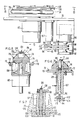
- the device is shown in FIG. 4 in side view.
- a plate 70 with sealing O-ring 72 is used to seal the valve and wafer handling arm into the system.
- the plate 70 is positioned in abutment with the main frame of the system.
- FIGS. 4-6 show that the valve wedge 74 and its operating mechanism, and the wafer handling arm 84 and its operating mechanism, are all attached to plate 70 to form a unitary structure.
- FIG. 8 shows that plate 70 is provided with slots 7l and an aperture 73 to receive bolts (not shown) for attaching the valve and wafer arm unit to the main frame of the system. This construction makes it possible to remove and replace the valve and wafer arm quickly as a single unit, and without dismantling any other portion of the system.
- the valve wedge 74 has O-rings 76, 78 on either side to seal to the valve seat 80 (shown in FIG. 3).
- a linear actuator 82 which may be pneumatically, hydraulically or electrically driven, is used to drive the valve wedge 74 upward into the seat 80. This upward movement is shown in FIG. 5 with the valve wedge 74 shown in dotted lines in the uppermost closed position.
- the wafer handling arm 84 remains at the same height in the system regardless of whether the valve wedge 74 is in the uppermost closed position or the lowermost open position.
- the valve wedge 74 has a storage notch 88 to allow the valve wedge 74 to pass around and seal the arm 84 within the valve.
- the wafer handling arm 84 is provided with two rotary actuators 90, 92 which drive concentric shafts 94, 96 through toothed belts 98, l00 and toothed pulleys l02, l04, l05, l06.
- the concentric shafts 94, 96 are mounted in a shaft holder l07 and supported at the top and bottom with roller bearings l08, ll0, ll2.
- two pairs of O-rings ll4, ll6, ll8, l20 are provided around each shaft.
- a hole l22 is provided through the outer shaft 96 which is in communication with a groove l24 on the inner shaft 94.
- a groove l26 on the outer shaft 96 communicates with the hole l22 and a pumping outlet l28 in order to provide other vacuum pumping or pressurization between each pair of O-ring seals on each shaft.
- a bellows seal l30 is provided between the valve wedge 74 and the plate 70.
- the handling arm 84 is made of four smaller pieces.
- a proximal support piece l32 is fixedly attached at a right angle at a first end to the outer shaft 96.
- a distal support piece l34 is pivotally attached at one end to the other end of the proximal support piece l32.
- a proximal extensor piece l36 is fixedly attached at a right angle at a first end to the inner shaft 94.
- a distal extensor piece l38 is pivotally attached at one end at the second end of the proximal extensor piece l36. The distal extensor piece l38 is pivotally attached at the second end of the distal support piece l34.
- the attachment points on the distal support piece l34 to the proximal support piece l32 and distal extensor piece l38 are separated by the dimension on the proximal extensor piece l36 between the attachment points.
- the proximal extensor piece l36 can be much shorter than the proximal support piece l32.
- the four pieces of the arm should form a pareallelogram between the attachment points and the shaft axis. If all four arm pieces are formed as blades, the pivotal attachments can be loosely fixed rivets.
- the arm thus described can be moved such that the tip holding the wafer moves in any complex trajectory by independently rotating the concentric shafts.
- the small space required to store the arm permits the arm to be stored within an isolation valve housing.
- the housing of the valve can be formed as a separate unit or as an integral part of the process chambers as shown previously. Mounting the driving means for the arm and make as shown previously permits the moving parts to be removed and replaced as a unit quickly, thus minimizing downtime.
- the valve may be pumped by the same pumping system as is used for the process chamber, either simultaneously or by time-sharing the pumping mechanism through alternating valves. If simultaneous pumping is necessary, the chemically active process gas being pumped out of the process chamber will backstream into the valve housing. This can be prevented by maintaining a small flow of an inert gas into the valve housing to continuously flush the housing and pump line. This flow can be as little as 5 cc/min.
- FIGS. l and l0 a loadlock and elevator mechanism is shown.
- the loadlock door l50 has attached to it a pair of rods l52 which ride on bearings l54 mounted to the outside of the loadlock chamber l56.
- the cassette 62 rides on a table l58 which is keyed to sit the cassette 62 in only one position.
- a microswitch l60 or other equivalent sensor is used to detect the cassette 62 when it is seated properly.
- the computer which controls the system is programmed to hold the loadlock door l50 open until the cassette 62 is properly seated.
- the table l58 rides on a shaft l62 which terminates in a bar l64.
- the bar l64 is driven by a screw l66 from a motor l68 and pulley l70.
- a guide rod l72 and bearing l74 is used to steady the elevator.
- a bellows l76 seals the chamber l56 to the bar l64 to provide vacuum sealing around the shaft l62.
- FIGS. l, l0 and ll there is an O-ring l78 located on the back of the door l50 which seals to the surface of the chamber l56 when the door is pushed closed.
- the main locking mechanism of the loadlock is the pressure of the atmosphere on the door l50 when the chamber l56 is evacuated through the pumping port l80.
- a vacuum or soft soft latch is provided to aid in compressing the O-ring l78 and in holding the door l50 until the pressure in the chamber l56 drops enough to hold the door l50 closed.
- the soft latch is comprised of as many as four O-ring seals l82, preferably of neoprene foam, mounted in the walls of the chamber l56 outside the O-ring l78 as shown in FIG. ll.
- These O-ring seals may be configured in a shape and size adequate to provide sufficient force to hold the door in intimate contact with the O-ring l78.
- the neoprene foam O-ring can be of the open-celled or closed-cell types, but a soft closed-cell neoprene O-ring works particularly well.
- ll is a view of the rear of the door as an example, with the position to which the O-ring seals l82 mate shown in phantom (since the seals l82 are on the face of the chamber).
- the O-ring seals l82 can be on the door, but it is more convenient to run the pumping channels through the chamber.
- Each seal l82 seals to a smooth surface on the back of the door l50 if the seals are on the chamber as illustrated. If the seals are on the door, the smooth surface is on the chamber.
- a hole l84 leads through a channel l86 to a valve and pumping system as shown in FIG. l2.
- a microswitch detector l88 detects the closing of the door l50.
- the valve to atmosphere l88 is closed and the valve to the pumping system l90 is opened in sequence.
- the vacuum drawn under the seals l82 then hold the door l50 closed.
- a switch l92 on the handle l94 is used to close the valve l90 to the pumping system and open the valve l88 to the atmosphere in sequence.
- the seals l82 then release the door.
- FIG. l3 there is shown an embodiment where a door l96, mounted on a hinge l97 and having only one sealing O-ring l98, has a single seal l98 mounted on the chamber to act as a soft latch. The position where the soft latch contacts the door is shown in phantom.
- the elevator is driven at a constant known speed so that position is known from the product of speed and time. Position is measured relative to the elevator table l58. Thus, position of each slot of the cassette and presence of each wafer is known.
- the control computer 24 is then programmed to pick up each wafer at the measured position in the computer memory and to skip cassette spaces where there is no wafer.
- the combination of wafer handling mechanism described before and wafer positioning system permits the system to be operated with random access to the wafers in the input cassette and random selection of cassette spaces to store the outgoing wafer.
- FIGS. l4-l6 there is shown the device for receiving, centering and holding the wafer during processing.
- the wafer is centered over the chuck platform 2l0 using the wafer handling arm.
- Lifting pins 2l2, in combinations of 3 or more, are raised under the wafer to lift the wafer off the handling arm.
- the handling arm is then withdrawn from the chamber.
- the wafer is then left on the lifting pins 2l2 with the pins in the extended position as shown in dotted lines in FIG. l5 and solid lines in FIG. l6.
- the lifting pins 2l2 are extended upward, the holding pins 2l4 are extended upward at a slant away from the wafer.
- Each holding pin 2l4 has a head enlargement 2l6 which is larger in diameter than the shaft of the holding pin.
- the head enlargement 2l6 may be formed as a small disk, cylinder or other object.
- the head enlargement 2l6 must be sufficiently large and abrupt to catch the edge of the wafer.
- the lifting pins 2l2 are drawn downward by the springs 2l3 to place the wafer on the top of the chuck platform 2l0, the holding pins 2l4 clamp the edge of the wafer with the heads 2l6.
- a capacitative sensor 2l8 is used to confirm the seating of a wafer on the chuck.
- Each holding pin 2l4 is fixed to a pin holder 220 which forms a guide for the pin.
- Each pin holder 220 is driven downward by a spring 222.
- the lifting pins 2l2 and the holding pins 2l4 are driven in common by a lifting table 224.
- the lifting table 224 has a rounded upper rim and the pin holder 220 has a rounded lower end to facilitate a smooth sliding motion of the pin holder 220 on the lifting table 224.
- the lifting table 224 is driven upward on a threaded shaft 226 and threaded cylinder 228.
- a bellows and O-ring seal 230 around the threaded cylinder 228 is used as a vacuum seal.
- the threaded shaft 226 is driven by a pulley 232 and motor 234.
- a wafer clamped firmly to a chuck platform 2l0 as previously described can be heated or cooled from the backside by gas fed from the interior of the chuck, the gas being used as a heat transfer medium between the chuck and the wafer.
- a plenum 236 is fed gas through an internal channel (not shown) from a source outside the vacuum.
- Radial channels 238 are used to feed the gas into a series of radial, concentric or combination (of radial and concentric) grooves on the surface of the chuck (not shown). Leakage of gas from under the wafer necessitates a continuous flow of gas.
- the temperature of the chuck is monitored with sensors and thereby regulated.
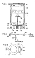
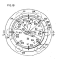
- FIGS. l7 and l8 Another chuck is shown in FIGS. l7 and l8.
- the wafer 300 is shown on the chuck surface 302.
- Three or more lifting pins 304 lift the wafer 300 off the handling arm as shown in phantom in FIG. l7 and lower the wafer 300 to the surface 302.
- the pins 304 are attached to a spider 306 and driven by a pneumatic actuator 308.
- Bellows 3l0 provide vacuum seals around the pins.
- Temperature control gas is introduced at the inlet 3l2 and passes through an interior channel 3l4 to a central well 3l6 in the surface 302 of the chuck.
- Channels 3l8 are provided for fluid for temperature regulation around the interior of the chuck.
- Radial slots 320 are provided on the surface 302 on the chuck connected to the well 3l6. Slot stops 322 block the slot and force the helium under the wafer.
- Each clamp comprises a thin hook 324 of sheet metal connected to a spring 326 arranged around the outside of the wafer.
- the slot 330 is optional as the hooks sit on the lifting ring 332 without the slots.
- the spreading ring is provided with two or more pneumatic actuators 334 (three are shown here) and bellows vacuum seal 336.
- the lifting ring 332 is likewise provided with two or more pneumatic actuators 338 (three are shown here) and bellows vacuum seal 340.
- Each hook 324 has an upper holding lip 342, lower spreading lip 344 and lifting slot 346.
- the spring 326 forces the hook 324 to pivot around the lifting ring 332 at the lifting slot 340 and push against the edge of the wafer 300, thus, centering the wafer amongst the hooks.
- the lifting ring 332 is lifted toward the wafer, the hook 324 is forced upward releasing the pressure on the top of the wafer at the holding lip 342.
- the hook 324 pivots outward around the lifting slot 346.
- the holding lip 342 then swings clear of the wafer 300 and the lifting pins 304 can be used to lift the wafer to the handling arm.
- a capacitance sensor 348 and/or an optical sensor 350 and/or a backside pressure sensor can be used to sense the presence of the wafer 300. This information is sent to the system computer 24.
- the main body of the chuck 352 can be removed to service the sensors 348 or 350 by removing the bolts 354 while leaving the clamping mechanism in place.
- the chuck may be heated with cartridge heaters and cooled with a fluid such as water.
- the fluid may be heated and cooled externally.
- the temperature of the chuck can be monitored with sensors and the temperature can be regulated with the aid of a control computer which may be combined with the processing computer 24.
- the task locator system is diagrammed.
- a system of two process chambers, three valves with wafer handlers and two loadlocks are used in this example. Any number of process chambers could be used with corresponding valves and wafer handlers.
- SND means vent or pump down the sender loadlock.
- Various task status symbols are defined at the right of the diagram.
- Status #l means the element is not ready or waiting to do anything.
- Status #2 means the element is ready to operate with a wafer present to be operated upon.
- Status #3 means the element is active. This code is not used in the matrix of the diagram in FIG. l9, but is defined for the sake of completeness.
- Status #4 means the element can be in status l or 2, but not 3.
- the fifth status symbol "any" means element can be in any of the other four status conditions.
- states of the tasks which can be only l, 2 or 3 and the required state which can be also l, 2 or the combinations 4 and 5.
- Most tasks proceed from l to 2 to 3 and back to l, except SND which proceeds from l to 2 to 3 and back to 2.
- SND which proceeds from l to 2 to 3 and back to 2.
- the status of ClP for example, is #l. After the wafer is moved into the chamber, the status changes to #2. Then the process begins and the status is changed to #3. When the process is finished the status changes back to #l.
- the valves will proceed through the same sequence of changes of status, but presence of a wafer is detected in the upstream compartment rather than in the valve itself. The only time there is a wafer in the valve itself is when the valve is active.
- the task locator system senses the actual status of each element of the system and stores that status in the computer according to the three categories of status named above. Each element is instructed to act independently of the actions of each other element if the status conditions of the other elements are correct. The system does not operate according to a fixed timed sequence.
- the task locator continuously compares actual status of the tasks labelled on the left of the matrix with each of the columns showing required status in the table diagrammed in FIG. l9 to determine if any task may be started. If the conditions are as shown in the table, it then starts those tasks and updates the status for the next time.
- the receiver valve between the second process chamber and the receiver loadlock will operate, read across the row of task names at the top to WRM, the second column from the end. Then read down to each status symbol and across to the left for the task name.
Landscapes
- Container, Conveyance, Adherence, Positioning, Of Wafer (AREA)
- Processing Of Stones Or Stones Resemblance Materials (AREA)
- Feeding Of Workpieces (AREA)
- Manipulator (AREA)
Applications Claiming Priority (2)
| Application Number | Priority Date | Filing Date | Title |
|---|---|---|---|
| US85327386A | 1986-04-17 | 1986-04-17 | |
| US853273 | 1986-04-17 |
Publications (1)
| Publication Number | Publication Date |
|---|---|
| EP0242996A2 true EP0242996A2 (de) | 1987-10-28 |
Family
ID=25315569
Family Applications (1)
| Application Number | Title | Priority Date | Filing Date |
|---|---|---|---|
| EP87302482A Withdrawn EP0242996A2 (de) | 1986-04-17 | 1987-03-23 | Förderarm für Plättchen |
Country Status (3)
| Country | Link |
|---|---|
| EP (1) | EP0242996A2 (de) |
| JP (1) | JPS62245645A (de) |
| KR (1) | KR870010616A (de) |
Cited By (1)
| Publication number | Priority date | Publication date | Assignee | Title |
|---|---|---|---|---|
| US7056392B1 (en) * | 2003-04-16 | 2006-06-06 | Lsi Logic Corporation | Wafer chucking apparatus and method for spin processor |
Families Citing this family (1)
| Publication number | Priority date | Publication date | Assignee | Title |
|---|---|---|---|---|
| US5030057A (en) * | 1987-11-06 | 1991-07-09 | Tel Sagami Limited | Semiconductor wafer transferring method and apparatus and boat for thermal treatment of a semiconductor wafer |
-
1987
- 1987-03-23 EP EP87302482A patent/EP0242996A2/de not_active Withdrawn
- 1987-04-14 JP JP62089964A patent/JPS62245645A/ja active Pending
- 1987-04-16 KR KR870003641A patent/KR870010616A/ko not_active Abandoned
Cited By (1)
| Publication number | Priority date | Publication date | Assignee | Title |
|---|---|---|---|---|
| US7056392B1 (en) * | 2003-04-16 | 2006-06-06 | Lsi Logic Corporation | Wafer chucking apparatus and method for spin processor |
Also Published As
| Publication number | Publication date |
|---|---|
| KR870010616A (ko) | 1987-11-30 |
| JPS62245645A (ja) | 1987-10-26 |
Similar Documents
| Publication | Publication Date | Title |
|---|---|---|
| US4764076A (en) | Valve incorporating wafer handling arm | |
| US4705951A (en) | Wafer processing system | |
| US4724621A (en) | Wafer processing chuck using slanted clamping pins | |
| US4713551A (en) | System for measuring the position of a wafer in a cassette | |
| CN216288355U (zh) | 一种晶圆转移系统 | |
| US5544421A (en) | Semiconductor wafer processing system | |
| US4701096A (en) | Wafer handling station | |
| US5951770A (en) | Carousel wafer transfer system | |
| US5882168A (en) | Semiconductor processing systems | |
| EP0250064A2 (de) | Platte mit mehrfachen dünnen Klemmitteln zum Behandeln von Plättchen | |
| US4457661A (en) | Wafer loading apparatus | |
| US20020032972A1 (en) | Substrate changing-over mechanism in vacuum tank | |
| US6520727B1 (en) | Modular sorter | |
| US6960257B2 (en) | Semiconductor processing system with wafer container docking and loading station | |
| US5836736A (en) | Semiconductor processing system with wafer container docking and loading station | |
| EP0242996A2 (de) | Förderarm für Plättchen | |
| EP0242064A2 (de) | Vakuumverschluss | |
| JP3310259B2 (ja) | 半導体製造装置及び半導体製造装置に於けるウェーハ移載方法及び半導体素子の製造方法 | |
| JPH09321120A (ja) | 半導体加工部材を処理するシステムおよび方法 | |
| KR20250081785A (ko) | 기판 반송 장치 및 그것을 구비한 기판 처리 장치 | |
| JP2007513790A (ja) | モジュラユニット | |
| JP2002329768A (ja) | 半導体製造装置及び半導体製造装置に於けるウェーハ移載方法及び半導体素子の製造方法 |
Legal Events
| Date | Code | Title | Description |
|---|---|---|---|
| PUAI | Public reference made under article 153(3) epc to a published international application that has entered the european phase |
Free format text: ORIGINAL CODE: 0009012 |
|
| AK | Designated contracting states |
Kind code of ref document: A2 Designated state(s): BE DE FR GB IT NL |
|
| STAA | Information on the status of an ep patent application or granted ep patent |
Free format text: STATUS: THE APPLICATION HAS BEEN WITHDRAWN |
|
| 18W | Application withdrawn |
Withdrawal date: 19880928 |
|
| R18W | Application withdrawn (corrected) |
Effective date: 19880928 |
|
| RIN1 | Information on inventor provided before grant (corrected) |
Inventor name: DICK, PAUL H. |