EP0243021A1 - Moyens d'adaptation d'impédance - Google Patents
Moyens d'adaptation d'impédance Download PDFInfo
- Publication number
- EP0243021A1 EP0243021A1 EP87302849A EP87302849A EP0243021A1 EP 0243021 A1 EP0243021 A1 EP 0243021A1 EP 87302849 A EP87302849 A EP 87302849A EP 87302849 A EP87302849 A EP 87302849A EP 0243021 A1 EP0243021 A1 EP 0243021A1
- Authority
- EP
- European Patent Office
- Prior art keywords
- impedance matching
- female
- male
- pin
- pins
- Prior art date
- Legal status (The legal status is an assumption and is not a legal conclusion. Google has not performed a legal analysis and makes no representation as to the accuracy of the status listed.)
- Withdrawn
Links
- 230000013011 mating Effects 0.000 claims description 9
- 239000004020 conductor Substances 0.000 claims description 6
- 230000000694 effects Effects 0.000 description 4
- 238000005476 soldering Methods 0.000 description 4
- 230000005540 biological transmission Effects 0.000 description 2
- 239000012811 non-conductive material Substances 0.000 description 2
- 230000008054 signal transmission Effects 0.000 description 2
- 239000004568 cement Substances 0.000 description 1
- 230000000593 degrading effect Effects 0.000 description 1
- 230000004907 flux Effects 0.000 description 1
Images
Classifications
-
- H—ELECTRICITY
- H01—ELECTRIC ELEMENTS
- H01R—ELECTRICALLY-CONDUCTIVE CONNECTIONS; STRUCTURAL ASSOCIATIONS OF A PLURALITY OF MUTUALLY-INSULATED ELECTRICAL CONNECTING ELEMENTS; COUPLING DEVICES; CURRENT COLLECTORS
- H01R13/00—Details of coupling devices of the kinds covered by groups H01R12/70 or H01R24/00 - H01R33/00
- H01R13/646—Details of coupling devices of the kinds covered by groups H01R12/70 or H01R24/00 - H01R33/00 specially adapted for high-frequency, e.g. structures providing an impedance match or phase match
- H01R13/6473—Impedance matching
- H01R13/6474—Impedance matching by variation of conductive properties, e.g. by dimension variations
- H01R13/6476—Impedance matching by variation of conductive properties, e.g. by dimension variations by making an aperture, e.g. a hole
-
- H—ELECTRICITY
- H01—ELECTRIC ELEMENTS
- H01R—ELECTRICALLY-CONDUCTIVE CONNECTIONS; STRUCTURAL ASSOCIATIONS OF A PLURALITY OF MUTUALLY-INSULATED ELECTRICAL CONNECTING ELEMENTS; COUPLING DEVICES; CURRENT COLLECTORS
- H01R12/00—Structural associations of a plurality of mutually-insulated electrical connecting elements, specially adapted for printed circuits, e.g. printed circuit boards [PCB], flat or ribbon cables, or like generally planar structures, e.g. terminal strips, terminal blocks; Coupling devices specially adapted for printed circuits, flat or ribbon cables, or like generally planar structures; Terminals specially adapted for contact with, or insertion into, printed circuits, flat or ribbon cables, or like generally planar structures
Definitions
- This invention relates to impedance matching means for a multi-pin connector.
- a multi-pin connector having impedance matching means comprising:
- a preferred embodiment of this invention may provide a multi-pin connector having matched impedance without increasing the number of mechanical components that must be mated and unmated and providing for improved pin alignment between male and female pins.
- An embodiment of the invention may provide an impedance matching block affixed to the component of the connector that supports one set of pins, preferably the female pins.
- the impedance matching block is made of electrically conductive material and has a series of holes through it at least one hole for each set of male and female pins to be mated.
- the block is in electrical contact with at least one of the ground pins or other source of ground potential.
- Each signal pin is generally centrally located with respect to a hole in the block and is spaced from the hole.
- "e r " is the dielectric constant of the medium between the conducting plates, which are in this case the signal pin and the block surrounding the signal pin. The medium, it is intended, is air.
- the present invention may be applicable to the field of apparatus for handling and conveying integrated circuit devices to a test site, comprising part of the apparatus, which interfaces with a tester for evaluating the quality of the integrated circuit devices.
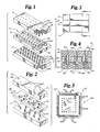
- Figure l shows a separated multi-pin connector generally at l0.
- the male connector member is indicated at l2 and the female connector member is at l4.
- Block l6 is shown between male connector member l2 and female connector member l4.
- male connector member l2 is made of an electrically non-conductive material and has three pin rows shown as signal male pin rows l8 and 20 on either side of ground male pin row 22.
- Each pin in pin rows l8, 20 and 22 is affixed in and supported by, male connector member l2 and protrudes from male connector member l2 in a downward direction.
- the upper end of each pin in signal male pin rows l8 and 20 is electrically connected, as by soldering, to suitable source of electrical signals.
- the upper end of each pin in ground male pin row 22 is electrically connected, as by soldering, to a source that is at electrical ground potential.
- Female connector member l4 is also made of electrically non-conductive material and has three rows of female pins, signal female pin rows 24 and 26 and ground female pin row 28. Each pin in pin rows 24, 26 and 28 is affixed in, and supported by, female connector member l4 and protrudes from female connector member l4 in an upward direction. The lower end of each pin in signal female pin rows 24 and 26 is electrically connected, as by soldering, to leads for the transmission of electric signals. The lower end of each pin in ground female pin row 28 is electrically connected, as by soldering, to leads for the transmission of electrical ground potential. There is a female pin in female connector member l4 that is axially aligned with, and is for mating with, each male pin in male connector member l2.
- block l6 is made of an electrically conductive material and has ground pin hole row 30, with a hole axially aligned with each pin in ground female pin row 28.
- the diameter of each such hole is only slightly greater than the diameter of the pin with which it is axially aligned in ground female pin row 28.
- the resulting close tolerances between the holes in ground pin hole row 30 and the pins in ground female pin row 28 result in a press fit between block l6 and female connector member l4 when block l6 and female connector member l4 are joined.
- Such a press fit makes an electrical connection between grounding block l6 and the pins of ground female pin row 28, thereby ensuring that they are of the same electrical potential.
- the press fit provides physical support for the pins of ground female pin row 28 by block l6, thereby assisting in maintaining the axial alignment of such pins with the pins of ground male pin row 22.
- impedance matching hole rows 32 and 34 Paralleling and on either side of ground pin hole row 30, are impedance matching hole rows 32 and 34.
- An impedance matching hole is provided for, and axially aligned with, each pair of male and female pins on male connector member l2 and female connector member l4.
- Each impedance matching hole is spaced from its respective pin a distance suitable to provide the desired impedance matching.
- Figure 2 shows generally at 36 another embodiment of a multi-pin connector with two marked variations from the embodiment shown in Figure l.
- male signal pins 44 are spaced from each other sufficient distances to permit non-overlapping impedance matching holes 46 to be bored in block 42.
- Each male signal pin 44 is paired with, and axially aligned with, a female signal pin 48 in female connector member 40.
- Each male signal pin 44 extends through male connector member 38 and may be connected at electrical connections 50 to electrical signal transmission means.
- each female signal pin 48 extends through female connector member 40 and may be connected to signal reception means at the underside of female connector member 40.
- ground potential is conveyed to block 42 by first ground strap 52 which is connected to a source of ground potential, and strap 52 extends through male connector member 38 to make electrical contact with block 42 when multi-pin connector 36 is in the connected condition.
- second ground strap 54 electrically contacts block 42 and extends through female connector member 40 at a surface of which it may be connected to ground potential reception means.
- Impedance matching block 42 is made of electrically conductive material. Each male signal pin 44 and its paired female signal pin 48 have a coaxial impedance matching hole 46 that is spaced therefrom a distance suitable to provide the desired impedance when multi-pin connector 36 is connected. Such impedance matching holes minimize the possibility of crosstalk between male signal pins 44. Since there are no grounding pins, grounding block 42 is affixed to either male connector member 38 or female member 40 with a suitable cement or the like. The alignment of impedance matching holes 46 coaxial with the paired male signal pins 44 and female signal pins 48 is provided for at the time of affixation.
- Figure 3 shows a multi-pin connector as shown in Figure l, generally at l0, in the connected condition.
- Grounding block l6 is closely sandwiched between male connector member l2 and female connector member l4.
- the height of block l6 is substantially equal to the height of each connected pair of male and female signal pins between male connector member l2 and female connector member l4.
- the grounding block is effective to match the impedance.
- the impedance to be matched was 50 ohms.
- Figure 4 shows, in section, a multi-pin connector as shown in Figure l generally at l0.
- Multi-pin connector l0 is shown in the connected position.
- Block l6 is press fit to female connector member l4 by the close tolerance of ground pin hole 30 and female ground pin 28.
- Female ground pin 28 extends through female connector member l4 and may be connected to ground potential reception means at electrical connection 74. The press fit also provides for electrical connection of female ground pin 28 and block l6.
- Male connector member l2 is electrically and physically joined with female connector member l4 by mating the male pins with the female pins.
- male signal pins l8, 20 are mated with female signal pins 24, 26 and male ground pins 22 are mated with female ground pins 28.
- Male signal pins l8, 20 extend through male connector member l2 and may be suitably electrically connected to signal sources at electrical connections 84, 85.
- Male ground pins may be similarly connected to a source of ground potential at electrical connection 86.
- Female signal pins 24, 26 may be connected to signal transmission means at electrical connection 88, 89.
- impedance matching block l6 it can be seen that its height is substantially equal to the height of the mated pair of male signal pins l8, 20 and female signal pins 24, 26 as measured between the bottom of male connector member l2 and the top of female connector member l4.
- Impedance matching holes 32, 34 are coaxial with, and spaced from, their respective mated pair of male signal pins l8, 20 and female signal pins 24, 26. The spacing provides the desired impedance.
- Figure 5 shows a top view of a multi-pin connector l04 with the impedance matching block 92 affixed to female connector member 94, visible only through impedance matching holes 96 and around female signal pins 98.
- Impedance matching block 92 is press fit to female connector member 94 by the close tolerance of ground pin holes l00 and ground pins l02.
- the embodiment of Figure 5 employs grounding pins defining a square configuration and can be used when testing integrated circuits having contacts along four edges thereof. The press fit provides for electrical connection of ground pins l02 and impedance matching block 92, thus ensuring that impedance matching block 92 is at ground potential.
- Impedance matching holes 96 are coaxial with, and spaced from, female signal pins 98, the spacing providing the desired impedance matching.
- adjacent impedance matching holes 96 overlap creating, in effect, a continuous slot with opposing serrations interposed half the distance between the axes of adjacent impedance matching holes 96.
- male connector member which would be similar in shape to female connector member 94 and have a male signal pin paired with each female signal pin 98 and a male ground pin paired with each female ground pin l02.
Landscapes
- Details Of Connecting Devices For Male And Female Coupling (AREA)
- Coupling Device And Connection With Printed Circuit (AREA)
- Connecting Device With Holders (AREA)
- Testing Of Individual Semiconductor Devices (AREA)
Applications Claiming Priority (2)
| Application Number | Priority Date | Filing Date | Title |
|---|---|---|---|
| US854331 | 1986-04-21 | ||
| US06/854,331 US4737116A (en) | 1986-04-21 | 1986-04-21 | Impedance matching block |
Publications (1)
| Publication Number | Publication Date |
|---|---|
| EP0243021A1 true EP0243021A1 (fr) | 1987-10-28 |
Family
ID=25318396
Family Applications (1)
| Application Number | Title | Priority Date | Filing Date |
|---|---|---|---|
| EP87302849A Withdrawn EP0243021A1 (fr) | 1986-04-21 | 1987-04-01 | Moyens d'adaptation d'impédance |
Country Status (3)
| Country | Link |
|---|---|
| US (1) | US4737116A (fr) |
| EP (1) | EP0243021A1 (fr) |
| JP (1) | JPS6312974A (fr) |
Cited By (14)
| Publication number | Priority date | Publication date | Assignee | Title |
|---|---|---|---|---|
| EP0418045A1 (fr) * | 1989-09-12 | 1991-03-20 | Nec Corporation | Connecteur à broches coaxiales avec une rangée de structures cylindriques conductrices creuses |
| EP0470775A1 (fr) * | 1990-08-07 | 1992-02-12 | ITT INDUSTRIES, INC. (a Delaware corporation) | Couplage électrique |
| EP0509992A4 (en) * | 1989-07-05 | 1992-11-04 | Labinal Components And Systems, Inc. | Electrical connectors |
| US5178549A (en) * | 1991-06-27 | 1993-01-12 | Cray Research, Inc. | Shielded connector block |
| US5211567A (en) * | 1991-07-02 | 1993-05-18 | Cray Research, Inc. | Metallized connector block |
| US5224918A (en) * | 1991-06-27 | 1993-07-06 | Cray Research, Inc. | Method of manufacturing metal connector blocks |
| GB2273397A (en) * | 1992-11-16 | 1994-06-15 | Krone Ag | Electrical connectors |
| EP0569528A4 (en) * | 1991-01-30 | 1995-10-18 | Labinal Components & Systems | Electrical connectors |
| US5597313A (en) | 1986-06-19 | 1997-01-28 | Labinal Components And Systems, Inc. | Electrical connectors |
| US5672062A (en) | 1991-01-30 | 1997-09-30 | Labinal Components And Systems, Inc. | Electrical connectors |
| US5704794A (en) * | 1986-12-29 | 1998-01-06 | Labinal Components And Systems, Inc. | Electrical connectors |
| EP1182913A1 (fr) * | 2000-08-25 | 2002-02-27 | Agere Systems Guardian Corporation | Interconnection de circuits à grande vitesse |
| WO2012118558A1 (fr) * | 2011-03-01 | 2012-09-07 | Tyco Electronics Corporation | Connecteur de bord de carte |
| CN111356287A (zh) * | 2018-03-15 | 2020-06-30 | 华为技术有限公司 | 连接板、电路板组件及电子设备 |
Families Citing this family (27)
| Publication number | Priority date | Publication date | Assignee | Title |
|---|---|---|---|---|
| US4875865A (en) * | 1988-07-15 | 1989-10-24 | Amp Incorporated | Coaxial printed circuit board connector |
| US4874319A (en) * | 1988-07-20 | 1989-10-17 | E. I. Du Pont De Nemours And Company | Terminal lead shielding for headers and connectors |
| US4941833A (en) * | 1988-10-06 | 1990-07-17 | Burndy Corporation | Controlled impedance plug and receptacle |
| DE9012949U1 (de) * | 1990-09-11 | 1991-01-03 | Siemens AG, 8000 München | Rückwandverdrahtung |
| US5567168A (en) * | 1990-09-27 | 1996-10-22 | The Whitaker Corporation | Electrical connector having electrostatic discharge protection |
| US5567169A (en) * | 1990-09-27 | 1996-10-22 | The Whitaker Corporation | Electrostatic discharge conductor to shell continuity |
| US5046960A (en) * | 1990-12-20 | 1991-09-10 | Amp Incorporated | High density connector system |
| US5219294A (en) * | 1991-02-20 | 1993-06-15 | Amp Incorporated | Electrical docking connector |
| US5302923A (en) * | 1992-07-16 | 1994-04-12 | Hewlett-Packard Company | Interconnection plate having high frequency transmission line through paths |
| US5674083A (en) * | 1995-11-22 | 1997-10-07 | The Whitaker Corporation | ESD protected electrical connector |
| US5882227A (en) * | 1997-09-17 | 1999-03-16 | Intercon Systems, Inc. | Controlled impedance connector block |
| US6000955A (en) * | 1997-12-10 | 1999-12-14 | Gabriel Technologies, Inc. | Multiple terminal edge connector |
| WO1999041810A1 (fr) * | 1998-02-17 | 1999-08-19 | Rambus, Inc. | Connecteur muni de contacts a configuration alternee |
| US6527587B1 (en) * | 1999-04-29 | 2003-03-04 | Fci Americas Technology, Inc. | Header assembly for mounting to a circuit substrate and having ground shields therewithin |
| US6250956B1 (en) * | 1999-11-09 | 2001-06-26 | Pulizzi Engineering Inc. | Electrical equipment and method of assembling same |
| US6695627B2 (en) | 2001-08-02 | 2004-02-24 | Fci Americas Technnology, Inc. | Profiled header ground pin |
| JP4689196B2 (ja) * | 2003-11-05 | 2011-05-25 | 日本発條株式会社 | 導電性接触子ホルダ、導電性接触子ユニット |
| USD563878S1 (en) * | 2007-08-16 | 2008-03-11 | Airborn, Inc. | Electrical connector |
| USD563879S1 (en) * | 2007-08-16 | 2008-03-11 | Airborn, Inc. | Electrical connector |
| USD563877S1 (en) * | 2007-08-16 | 2008-03-11 | Airborn, Inc. | Electrical connector |
| USD563880S1 (en) * | 2007-08-16 | 2008-03-11 | Airborn, Inc. | Electrical connector |
| US7641516B1 (en) * | 2008-09-19 | 2010-01-05 | Harris Corporation | Electrical connector |
| USD704644S1 (en) * | 2011-12-30 | 2014-05-13 | Harris Corporation | Electrical connector |
| CN203850501U (zh) * | 2013-12-27 | 2014-09-24 | 富士康(昆山)电脑接插件有限公司 | 电连接器 |
| US9472887B1 (en) * | 2015-04-22 | 2016-10-18 | Tyco Electronics Corporation | Electrical connector having a ground bracket |
| JP1600681S (fr) * | 2017-05-30 | 2018-03-26 | ||
| JP1600060S (fr) * | 2017-05-30 | 2018-03-19 |
Citations (4)
| Publication number | Priority date | Publication date | Assignee | Title |
|---|---|---|---|---|
| US3643201A (en) * | 1970-02-09 | 1972-02-15 | Amp Inc | Impedance matching microstrip connector |
| US3871728A (en) * | 1973-11-30 | 1975-03-18 | Itt | Matched impedance printed circuit board connector |
| WO1984002631A1 (fr) * | 1982-12-29 | 1984-07-05 | Western Electric Co | Emballage de puce a semiconducteur |
| US4534602A (en) * | 1982-05-26 | 1985-08-13 | Fairchild Camera & Instrument Corp. | R.F. multi-pin connector |
Family Cites Families (5)
| Publication number | Priority date | Publication date | Assignee | Title |
|---|---|---|---|---|
| US3205295A (en) * | 1963-03-18 | 1965-09-07 | Burroughs Corp | Electrical connector |
| US3550065A (en) * | 1968-01-11 | 1970-12-22 | G & H Technology | Electrical connector |
| US3621444A (en) * | 1970-06-01 | 1971-11-16 | Elco Corp | Integrated circuit module electrical connector |
| US4431251A (en) * | 1981-10-13 | 1984-02-14 | The Bendix Corporation | Electrical connector with a built in circuit protection device |
| US4457574A (en) * | 1982-02-05 | 1984-07-03 | Automation Industries, Inc. | Electromagnetically shielded connector |
-
1986
- 1986-04-21 US US06/854,331 patent/US4737116A/en not_active Expired - Fee Related
-
1987
- 1987-04-01 EP EP87302849A patent/EP0243021A1/fr not_active Withdrawn
- 1987-04-20 JP JP62095485A patent/JPS6312974A/ja active Pending
Patent Citations (4)
| Publication number | Priority date | Publication date | Assignee | Title |
|---|---|---|---|---|
| US3643201A (en) * | 1970-02-09 | 1972-02-15 | Amp Inc | Impedance matching microstrip connector |
| US3871728A (en) * | 1973-11-30 | 1975-03-18 | Itt | Matched impedance printed circuit board connector |
| US4534602A (en) * | 1982-05-26 | 1985-08-13 | Fairchild Camera & Instrument Corp. | R.F. multi-pin connector |
| WO1984002631A1 (fr) * | 1982-12-29 | 1984-07-05 | Western Electric Co | Emballage de puce a semiconducteur |
Non-Patent Citations (1)
| Title |
|---|
| IBM TECHNICAL DISCLOSURE BULLETIN, vol. 22, no. 6, November 1979, pages 2309-2310; E. KIMMERLE et al.: "Multicontact plug with improved grounding" * |
Cited By (19)
| Publication number | Priority date | Publication date | Assignee | Title |
|---|---|---|---|---|
| US5597313A (en) | 1986-06-19 | 1997-01-28 | Labinal Components And Systems, Inc. | Electrical connectors |
| US5704794A (en) * | 1986-12-29 | 1998-01-06 | Labinal Components And Systems, Inc. | Electrical connectors |
| EP0647088A3 (fr) * | 1989-07-05 | 1995-05-03 | Labinal Components & Systems | |
| EP0509992A4 (en) * | 1989-07-05 | 1992-11-04 | Labinal Components And Systems, Inc. | Electrical connectors |
| EP0418045A1 (fr) * | 1989-09-12 | 1991-03-20 | Nec Corporation | Connecteur à broches coaxiales avec une rangée de structures cylindriques conductrices creuses |
| EP0470775A1 (fr) * | 1990-08-07 | 1992-02-12 | ITT INDUSTRIES, INC. (a Delaware corporation) | Couplage électrique |
| US5672062A (en) | 1991-01-30 | 1997-09-30 | Labinal Components And Systems, Inc. | Electrical connectors |
| US5704795A (en) | 1991-01-30 | 1998-01-06 | Labinal Components And Systems, Inc. | Electrical connectors |
| EP0569528A4 (en) * | 1991-01-30 | 1995-10-18 | Labinal Components & Systems | Electrical connectors |
| US5224918A (en) * | 1991-06-27 | 1993-07-06 | Cray Research, Inc. | Method of manufacturing metal connector blocks |
| US5178549A (en) * | 1991-06-27 | 1993-01-12 | Cray Research, Inc. | Shielded connector block |
| US5400504A (en) * | 1991-07-02 | 1995-03-28 | Cray Research, Inc. | Method of manufacturing metallized connector block |
| US5211567A (en) * | 1991-07-02 | 1993-05-18 | Cray Research, Inc. | Metallized connector block |
| GB2273397A (en) * | 1992-11-16 | 1994-06-15 | Krone Ag | Electrical connectors |
| EP1182913A1 (fr) * | 2000-08-25 | 2002-02-27 | Agere Systems Guardian Corporation | Interconnection de circuits à grande vitesse |
| WO2012118558A1 (fr) * | 2011-03-01 | 2012-09-07 | Tyco Electronics Corporation | Connecteur de bord de carte |
| CN111356287A (zh) * | 2018-03-15 | 2020-06-30 | 华为技术有限公司 | 连接板、电路板组件及电子设备 |
| US11166374B2 (en) | 2018-03-15 | 2021-11-02 | Huawei Technologies Co., Ltd. | Connection plate, circuit board assembly, and electronic device |
| US11706871B2 (en) | 2018-03-15 | 2023-07-18 | Huawei Technologies Co., Ltd. | Connection plate, circuit board assembly, and electronic device |
Also Published As
| Publication number | Publication date |
|---|---|
| JPS6312974A (ja) | 1988-01-20 |
| US4737116A (en) | 1988-04-12 |
Similar Documents
| Publication | Publication Date | Title |
|---|---|---|
| EP0243021A1 (fr) | Moyens d'adaptation d'impédance | |
| EP0589492B1 (fr) | Connecteurs électriques | |
| US5120258A (en) | Low inductance shielded cable to printed circuit board connection apparatus | |
| US4710133A (en) | Electrical connectors | |
| US3651432A (en) | Impedance matched printed circuit connectors | |
| US4365856A (en) | Electric connector for coaxial ribbon cable | |
| US7131862B2 (en) | Electrical connector with horizontal ground plane | |
| US5062809A (en) | High-frequency connector and method of manufacturing thereof | |
| CN109565122B (zh) | 直接附连连接器 | |
| EP0859433A3 (fr) | ContrÔle d'impédance et d'inductance en connecteurs électriques à diaphonie réduite | |
| CA2352820A1 (fr) | Carte imprimee et son procede de fabrication | |
| US5704794A (en) | Electrical connectors | |
| US5704795A (en) | Electrical connectors | |
| EP0265179A2 (fr) | Prise à fiches et connecteur à douilles avec contacts à déplacement d'isolant | |
| EP0395609A1 (fr) | Connecteur de surface pour signaux de radio-fréquence | |
| EP1082789B1 (fr) | Connecteur filete a faisceaux de fils comprimes double face | |
| EP1014513B1 (fr) | Circuit imprimé pour fiche modulaire | |
| US5004427A (en) | Electrical connectors | |
| JPH05182720A (ja) | 電気コネクタ | |
| EP0569528B1 (fr) | Assemblage de connecteur electriques | |
| US6929482B2 (en) | Interconnection arrangement | |
| US6716067B2 (en) | Multi-connector for use in high-speed communication apparatus and method for mounting the same multi-connector into printed board | |
| EP0347316A2 (fr) | Connecteur de ligne à bande aux micro-ondes | |
| EP1343217A2 (fr) | Transition entre une ligne de transmission coaxiale et une ligne de transmission sur un circuit imprimé | |
| US20030169124A1 (en) | Transition from a coaxial transmission line to a printed circuit transmission line |
Legal Events
| Date | Code | Title | Description |
|---|---|---|---|
| PUAI | Public reference made under article 153(3) epc to a published international application that has entered the european phase |
Free format text: ORIGINAL CODE: 0009012 |
|
| AK | Designated contracting states |
Kind code of ref document: A1 Designated state(s): DE FR GB |
|
| 17P | Request for examination filed |
Effective date: 19880418 |
|
| STAA | Information on the status of an ep patent application or granted ep patent |
Free format text: STATUS: THE APPLICATION IS DEEMED TO BE WITHDRAWN |
|
| 18D | Application deemed to be withdrawn |
Effective date: 19901103 |
|
| RIN1 | Information on inventor provided before grant (corrected) |
Inventor name: SLYE, BRADLEY D Inventor name: JOHNSON, DAVID A |