EP0243119B1 - Komplex geformte geklöppelte Struktur - Google Patents
Komplex geformte geklöppelte Struktur Download PDFInfo
- Publication number
- EP0243119B1 EP0243119B1 EP87303414A EP87303414A EP0243119B1 EP 0243119 B1 EP0243119 B1 EP 0243119B1 EP 87303414 A EP87303414 A EP 87303414A EP 87303414 A EP87303414 A EP 87303414A EP 0243119 B1 EP0243119 B1 EP 0243119B1
- Authority
- EP
- European Patent Office
- Prior art keywords
- yarns
- array
- braiding
- braiding yarns
- outside
- Prior art date
- Legal status (The legal status is an assumption and is not a legal conclusion. Google has not performed a legal analysis and makes no representation as to the accuracy of the status listed.)
- Expired - Lifetime
Links
Images


Classifications
-
- D—TEXTILES; PAPER
- D04—BRAIDING; LACE-MAKING; KNITTING; TRIMMINGS; NON-WOVEN FABRICS
- D04C—BRAIDING OR MANUFACTURE OF LACE, INCLUDING BOBBIN-NET OR CARBONISED LACE; BRAIDING MACHINES; BRAID; LACE
- D04C3/00—Braiding or lacing machines
-
- D—TEXTILES; PAPER
- D04—BRAIDING; LACE-MAKING; KNITTING; TRIMMINGS; NON-WOVEN FABRICS
- D04C—BRAIDING OR MANUFACTURE OF LACE, INCLUDING BOBBIN-NET OR CARBONISED LACE; BRAIDING MACHINES; BRAID; LACE
- D04C3/00—Braiding or lacing machines
- D04C3/48—Auxiliary devices
-
- B—PERFORMING OPERATIONS; TRANSPORTING
- B29—WORKING OF PLASTICS; WORKING OF SUBSTANCES IN A PLASTIC STATE IN GENERAL
- B29C—SHAPING OR JOINING OF PLASTICS; SHAPING OF MATERIAL IN A PLASTIC STATE, NOT OTHERWISE PROVIDED FOR; AFTER-TREATMENT OF THE SHAPED PRODUCTS, e.g. REPAIRING
- B29C70/00—Shaping composites, i.e. plastics material comprising reinforcements, fillers or preformed parts, e.g. inserts
- B29C70/04—Shaping composites, i.e. plastics material comprising reinforcements, fillers or preformed parts, e.g. inserts comprising reinforcements only, e.g. self-reinforcing plastics
- B29C70/06—Fibrous reinforcements only
- B29C70/10—Fibrous reinforcements only characterised by the structure of fibrous reinforcements, e.g. hollow fibres
- B29C70/16—Fibrous reinforcements only characterised by the structure of fibrous reinforcements, e.g. hollow fibres using fibres of substantial or continuous length
- B29C70/24—Fibrous reinforcements only characterised by the structure of fibrous reinforcements, e.g. hollow fibres using fibres of substantial or continuous length oriented in at least three directions forming a three-dimensional [3D] structure
-
- D—TEXTILES; PAPER
- D04—BRAIDING; LACE-MAKING; KNITTING; TRIMMINGS; NON-WOVEN FABRICS
- D04C—BRAIDING OR MANUFACTURE OF LACE, INCLUDING BOBBIN-NET OR CARBONISED LACE; BRAIDING MACHINES; BRAID; LACE
- D04C1/00—Braid or lace, e.g. pillow-lace; Processes for the manufacture thereof
- D04C1/06—Braid or lace serving particular purposes
-
- D—TEXTILES; PAPER
- D04—BRAIDING; LACE-MAKING; KNITTING; TRIMMINGS; NON-WOVEN FABRICS
- D04C—BRAIDING OR MANUFACTURE OF LACE, INCLUDING BOBBIN-NET OR CARBONISED LACE; BRAIDING MACHINES; BRAID; LACE
- D04C3/00—Braiding or lacing machines
- D04C3/02—Braiding or lacing machines with spool carriers guided by track plates or by bobbin heads exclusively
- D04C3/04—Braiding or lacing machines with spool carriers guided by track plates or by bobbin heads exclusively with spool carriers guided and reciprocating in non-endless paths
-
- D—TEXTILES; PAPER
- D04—BRAIDING; LACE-MAKING; KNITTING; TRIMMINGS; NON-WOVEN FABRICS
- D04C—BRAIDING OR MANUFACTURE OF LACE, INCLUDING BOBBIN-NET OR CARBONISED LACE; BRAIDING MACHINES; BRAID; LACE
- D04C3/00—Braiding or lacing machines
- D04C3/02—Braiding or lacing machines with spool carriers guided by track plates or by bobbin heads exclusively
- D04C3/06—Braiding or lacing machines with spool carriers guided by track plates or by bobbin heads exclusively with spool carriers moving always in the same direction in endless paths
-
- D—TEXTILES; PAPER
- D04—BRAIDING; LACE-MAKING; KNITTING; TRIMMINGS; NON-WOVEN FABRICS
- D04C—BRAIDING OR MANUFACTURE OF LACE, INCLUDING BOBBIN-NET OR CARBONISED LACE; BRAIDING MACHINES; BRAID; LACE
- D04C3/00—Braiding or lacing machines
- D04C3/02—Braiding or lacing machines with spool carriers guided by track plates or by bobbin heads exclusively
- D04C3/12—Braiding or lacing machines with spool carriers guided by track plates or by bobbin heads exclusively with means for introducing core threads
-
- D—TEXTILES; PAPER
- D10—INDEXING SCHEME ASSOCIATED WITH SUBLASSES OF SECTION D, RELATING TO TEXTILES
- D10B—INDEXING SCHEME ASSOCIATED WITH SUBLASSES OF SECTION D, RELATING TO TEXTILES
- D10B2403/00—Details of fabric structure established in the fabric forming process
- D10B2403/02—Cross-sectional features
- D10B2403/024—Fabric incorporating additional compounds
- D10B2403/0241—Fabric incorporating additional compounds enhancing mechanical properties
- D10B2403/02411—Fabric incorporating additional compounds enhancing mechanical properties with a single array of unbent yarn, e.g. unidirectional reinforcement fabrics
-
- D—TEXTILES; PAPER
- D10—INDEXING SCHEME ASSOCIATED WITH SUBLASSES OF SECTION D, RELATING TO TEXTILES
- D10B—INDEXING SCHEME ASSOCIATED WITH SUBLASSES OF SECTION D, RELATING TO TEXTILES
- D10B2403/00—Details of fabric structure established in the fabric forming process
- D10B2403/02—Cross-sectional features
- D10B2403/024—Fabric incorporating additional compounds
- D10B2403/0243—Fabric incorporating additional compounds enhancing functional properties
-
- D—TEXTILES; PAPER
- D10—INDEXING SCHEME ASSOCIATED WITH SUBLASSES OF SECTION D, RELATING TO TEXTILES
- D10B—INDEXING SCHEME ASSOCIATED WITH SUBLASSES OF SECTION D, RELATING TO TEXTILES
- D10B2403/00—Details of fabric structure established in the fabric forming process
- D10B2403/03—Shape features
- D10B2403/033—Three dimensional fabric, e.g. forming or comprising cavities in or protrusions from the basic planar configuration, or deviations from the cylindrical shape as generally imposed by the fabric forming process
- D10B2403/0333—Three dimensional fabric, e.g. forming or comprising cavities in or protrusions from the basic planar configuration, or deviations from the cylindrical shape as generally imposed by the fabric forming process with tubular portions of variable diameter or distinct axial orientation
-
- D—TEXTILES; PAPER
- D10—INDEXING SCHEME ASSOCIATED WITH SUBLASSES OF SECTION D, RELATING TO TEXTILES
- D10B—INDEXING SCHEME ASSOCIATED WITH SUBLASSES OF SECTION D, RELATING TO TEXTILES
- D10B2505/00—Industrial
- D10B2505/02—Reinforcing materials; Prepregs
Definitions
- This invention relates to complex shaped structures and more particularly it relates to three dimensional braided structures of a structural composite material.
- Fiber-reinforced plastic structures have been used for many years with increasing success because of their high strength, light weight and ease of fabrication compared to the wood or metal structures which they replace. Fibers such as glass, carbon, ceramic and aramid are popular as reinforcement, and thermosetting as well as thermoplastic resins are common polymeric matrices.
- Polymeric materials reinforced with continuous filaments are used as precursors for highly-stressed parts such as aerospace components requiring the highest possible strength and stiffness with the lowest possible weight. Non-uniformity of such parts requires that the parts be over-constructed so that the weakest will surpass the service requirements. Integral manufacture of complex structures could improve uniformity of the reinforcing material and reliability of the composite part made from such structures.
- Braiding with axial yarns is one process for producing such structures and generally comprises forming an array of axial yarns extending substantially parallel to the axis of the structure and interlacing braiding yarns in a pattern through the array so they are interlaced with one another and with the axial yarns.
- Known processes for doing this such as described in European Patent Publication No. 0113196, do not lend themselves to forming complex shaped structures at relatively high processing speeds and it would be highly desirable to do so.
- US-A-4614147 discloses a method and apparatus for forming a braided structure.
- the apparatus comprises a plate through which are passed the axial yarns in a direction perpendicular to the plane of the plate.
- the axial yarns are arranged in a regular pattern of rows and columns.
- At the edges of the plate are arranged jacks, each carrying a spool of braiding yarn.
- the jacks are aligned with a column, row or diagonal of axial yarns.
- the jacks of US-A-4614147 push the spools of braiding yarn across the plate, to halfway across each column, row or diagonal to be interconnected by braiding yarn.
- the jacks are then withdrawn and the spool return step next commences.
- the spool return step the jacks within each pair are moved sideways so that their positions are transposed.
- the jacks are then extended to pick up the spools deposited by the opposed jacks.
- the jacks are retracted and the spools thus complete their passage along their respective columns, rows or diagonals of axial yarn.
- the jacks are again moved sideways, to return to their original positions. In this way, the braiding yarns follow an L-shaped path.
- This invention through a unique braiding pattern, allows manipulation of the yarns to form complex shaped structures with precise yarn placement at relatively high processing speeds.
- the method of forming such structures includes moving the braiding yarns in a repeating two-step pattern such that the braiding yarns follow diagonal paths through a multi-layer axial array of yarns that extend longitudinally in the structure.
- the braiding yarns are moved in opposite directions in the first and second steps in an interlacing pattern and such that they interconnect with other braiding yarns.
- the method is characterised in that all of the braiding yarns in the structure in the first step along its respective diagonal path to a reversal point outside of the array and then move in another diagonal direction, the yarns completing the first step before any of them starts the second.
- All braiding yarns are outside the array at their reversal points simultaneously.
- the product formed is defined in terms of the braiding yarns and axial yarns.
- the improvement is in the interlacing pattern wherein said braiding yarns extend in diagonal paths to the periphery of the structure to reversal points outside the array before any of said braiding yarns extends in a path in another diagonal direction from its reversal point.
- the arrangement of yarns provides directional reinforcement and structural shape with a relatively small number of braiding yarns.
- a matrix material may be added to any of the structures made by this invention to form a rigid composite.
- a three-dimensional braided structure can be shaped as a T-beam and rigidized to form a structural member.
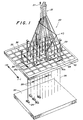
- the braided structures of this invention are preferably made on an apparatus such as that schematically shown in Fig. 1 wherein a two-step motion as shown in Figs. 2a-2c is used to interlace braiding yarns with axial yarns and with each other in a pattern to obtain the benefits of the invention.
- a braiding machine generally designated 20 is fed from a creel 22 supporting supply packages 24 of yarns 26 which are moved through guide tubes 28 in grid support 30 in a multi-layer array.
- the yarns 26 are referred to as axial yarns and they extend substantially parallel to the longitudinal axis of the T structure 32 being formed by the braiding operation.
- Braiding yarns 40 are fed from supply packages 42 mounted on carriers 44 (such as model KL80B mfg. by Steeger, Inc.) which are movable in grid support 30 in the X and Y directions along grooves 33, 35 in the support 30 by means of positive acting drives indicated by arrows 33a, 35a in a pattern to be described later in connection with Figs. 2a through 2e.
- carriers 44 are shown at selected reversal points in a pattern for forming the T-shaped structure 32.
- Braiding motion is accomplished by moving the carriers through the axial yarn array first along selected X grooves 33 of the grid and subsequently along selected Y grooves 35 of the grid.
- the continuous repetition of these two X and Y steps combined with an axial advance of the structure 32 provided by puller mechanism indicated by the arrow 37 forms three dimensional braided structures of complex geometry, such as the braided T-beam structure 32.
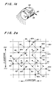
- axial yarns 26 are arranged in the grid 30 in the geometric shape 31 of a T-beam. Braiding yarns 40 are placed at alternating reversal points 50. There are eight (8) braiding yarns shown and designated 40a through 40h. These are positioned at alternating reversal points in both the X and Y directions of the grid. In the first step of the braiding operation each of the yarns 40a through 40h are moved in either the plus (+) or minus (-) direction as indicated by the arrows or displacement vectors through the array of axial yarns 26 (Fig. 2b) to the first empty reversal point 50, i.e.
- the second step of the braiding operation moves the braiding yarns orthogonally in either the X or Y direction as shown by the arrows or displacement vectors in Fig. 2c to the first empty reversal point, i.e., 40d, 40e, 40f and 40h move in the plus (+) direction while 40a, 40b, 40c and 40g move in the minus (-) direction.
- the pattern by which yarns 40a, 40e, 40c, 40g and 40d interlace the axial array of yarn 26 is shown in Fig. 2d.
- the pattern by which yarns 40b, 40f and 40h interlace the axial yarns is shown in Fig. 2e.
- the motion patterns described for making a T-beam can be generalized for making any cross-sectional shape as follows.
- each axial yarn 26 is placed in the centre of a grid unit.
- the arrangement of axial yarns is limited to those in which a boundary line connecting the centres of the boundary axial yarns must be made exclusively of line segments which are ⁇ 45° to the grid lines in the X and Y directions. See for example the boundary line 31 on Fig. 2a. Note that multi- boundary shaped structures such as those in Fig. 8 can also be selected.
- the pivotal braider Locate the braiding yarns at alternate reversal points along the boundary starting with the lowest X reversal point in the lowest Y row, designated as the pivotal braider.
- alternate braiding yarns so that the first machine motion provides an empty space for each yarn. These are designated 40a through 40h in Fig. 2a.
- the pivotal braider is 40e.
- step one of the braiding motion move all braiding yarns simultaneously in the X direction to the nearest empty reversal point alternating plus or minus with every Y row, with the row including the pivotal braider moving in the plus direction.
- step two of the braiding motion move all braiding yarns simultaneously in the Y direction to the nearest empty reversal point alternating plus or minus with every X row, with the row including the pivotal braider moving in the plus direction.
- this motion is defined as moving through the array.
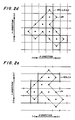
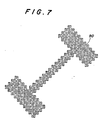
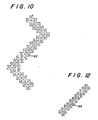
- Figs. 7-12 illustrate a variety of cross-sectional shapes which can be made using the principles of this invention. Each figure shows the required two steps of braider motion. Dotted lines indicate the first step (or X direction movement) used to produce the structures. Solid lines indicate the second step (or Y direction movement used). More particularly, Fig. 7 is a motion diagram of an I-beam 90 with varying wall thickness; Fig. 8 is a motion diagram of a box beam structure 91; Fig. 9 is a motion diagram of a pseudo-circular structure 92; and Fig. 10 is a motion diagram of a Z-beam structure 93.
- Fig. 11 shows a tubular structure formed using two-step principles but laid out on a non-orthogonal grid. More particularly, referring to Fig. 11a the centre 81 of the grid element 80 is defined as the point where internal diagonals 82, 83 intersect. A unit grid spacing is defined as the length of the longst side 84 of the quadrilateral on its boundary. Line segments which connect the centre of the boundary axials 81 must be along the diagonals to the grid. Diagonals 85 of the grid are defined as lines which connect the centres of grid elements with a common vertex 86.
- a number of structural variations may be achieved by techniques other than varying the braiding pattern. More particularly, in Fig. 3 a T-beam structure 59 with structural voids 60 is shown. This structure is produced using the same principles as outlined above except that rubber rods are substituted for some axial yarns and later removed after formation and consolidation. Structural voids increase the stiffness per weight of these beams. In addition, these voids provide useful connectors as shown on Fig. 3a. Dowels 61 may be cemented into voided areas and mated with like structure also having voids.
- a bent beam structure 62 as shown in Fig. 4 is produced using the same principles and the apparatus of Fig. 1a.
- the output of the braiding apparatus is pulled over a surface 64 having a radius R in the direction of arrow 63 so that yarns on the outside of the bend are introduced into the structure at a greater rate than those on the inside thus forming a curved section.
- a structural beam 66 with lengthwise variations as shown in Fig. 5 can be produced by changing the speed of the puller mechanism (not shown). As illustrated, high braiding angles are formed in sections 67 of the beam by operating the movement of the puller mechanism at a relatively slow rate. Lower braiding angles are effected in section 68, e.g., approaching a parallel relationship with the axial yarns by operating the movement of the puller mechanism at a relatively fast rate.
- a beam with braided ends can be drilled readily at its ends to form strong attachment points.
- a bifurcated structure as illustrated in Fig. 6 may be produced using this invention.
- the braiding apparatus is initially set up to make a rectangular array 70. After a series of moves, the axial yarns are repositioned to form two rectangular areas 71 and 72 separated by a space 73. The structure changes in cross section along its length.
- a T-beam structure is prepared by providing 27 groups of axial yarns of 7,200 denier (8,000 dtex) carbon fiber (AS-4 made by Hercules, Inc.) and 12 groups of braiding yarns of 15,000 denier (16.667 dtex) Kevlar O aramid fiber.
- the axial yarnxuv- roups include 16 yarn ends in each of the 15 groups of the flange portion and eight yarn ends in each of 12 groups of the web portion.
- the braiding yarn groups each have two yarn ends.
- the braided structure is prepared by the two-step motion detailed above. The braided structure is removed from the braiding apparatus and consolidated by impregnating the structure with an epoxy resin (EPON O 815, mfg. by Shell Chemical Company).
- the impregnation involves dipping the braided structure in the resin and/or injecting the resin into the braided structure with a large hypodermic needle.
- the structure is exposed to vacuum to remove any air pockets.
- the impregnated structure is placed in a T-shape mold and mechanical pressure of approximately 50 psi (345 kPa) is applied while heating the mold to a temperature of about 120°F (49°C) for two hours. Then the mold is allowed to cool to room temperature under pressure before removing the structure from the mold.
- a bent beam structure is prepared by providing 33 groups of axial yarns of 9,011 total denier (10,012 dtex) fibreglass yarns coated with thermoplastic polymer and 14 groups of braiding yarns of the same denier and composition as the axial yarns.
- the particular polymer used was that disclosed by Chang in U.S. Patent No. 4,511,690.
- the axial yarn groups include 14 yarn ends in each of the 22 axial groups on the periphery of the structure and 15 yarn ends in each of the 11 axials on the inside of the structure.
- the braiding yarn groups each have 4 yarn ends.
- the braided structure is prepared using the pattern 94 shown in Fig. 12 by the two-step motion and pulled over a contoured surface similar to that shown in Fig. 1a.
- the braided structure is removed from the braiding apparatus and consolidated by placing the structure in a mold and first applying a mechanical pressure of 100 psi (689 kPa) while heating to 290°C. After reaching 290°C the mechanical pressure is increased to 1000 psi (6.89 MPa) while heating at 290°C to 300°C for 15 minutes. The structure is cooled to room temperature in the mold while applying a mechanical pressure of 1000 psi (6.89 MPa).
Landscapes
- Engineering & Computer Science (AREA)
- Textile Engineering (AREA)
- Chemical & Material Sciences (AREA)
- Composite Materials (AREA)
- Mechanical Engineering (AREA)
- Manufacturing & Machinery (AREA)
- Braiding, Manufacturing Of Bobbin-Net Or Lace, And Manufacturing Of Nets By Knotting (AREA)
- Rod-Shaped Construction Members (AREA)
Claims (9)
Applications Claiming Priority (2)
| Application Number | Priority Date | Filing Date | Title |
|---|---|---|---|
| US853742 | 1986-04-17 | ||
| US06/853,742 US4719837A (en) | 1986-04-17 | 1986-04-17 | Complex shaped braided structures |
Publications (2)
| Publication Number | Publication Date |
|---|---|
| EP0243119A1 EP0243119A1 (de) | 1987-10-28 |
| EP0243119B1 true EP0243119B1 (de) | 1991-01-23 |
Family
ID=25316781
Family Applications (1)
| Application Number | Title | Priority Date | Filing Date |
|---|---|---|---|
| EP87303414A Expired - Lifetime EP0243119B1 (de) | 1986-04-17 | 1987-04-16 | Komplex geformte geklöppelte Struktur |
Country Status (11)
| Country | Link |
|---|---|
| US (1) | US4719837A (de) |
| EP (1) | EP0243119B1 (de) |
| JP (1) | JPS62250258A (de) |
| KR (1) | KR870010236A (de) |
| AU (1) | AU584063B2 (de) |
| BR (1) | BR8701798A (de) |
| CA (1) | CA1285799C (de) |
| DE (1) | DE3767543D1 (de) |
| ES (1) | ES2020270B3 (de) |
| IL (1) | IL82220A (de) |
| TR (1) | TR22779A (de) |
Cited By (1)
| Publication number | Priority date | Publication date | Assignee | Title |
|---|---|---|---|---|
| US10159297B2 (en) | 2013-05-21 | 2018-12-25 | Bradford C. Jamison | Patterned plexus of filaments, method of producing and articles containing patterned filaments |
Families Citing this family (87)
| Publication number | Priority date | Publication date | Assignee | Title |
|---|---|---|---|---|
| EP0244120A3 (de) * | 1986-04-16 | 1989-07-12 | Courtaulds Plc | Element aus Verbundwerkstoff |
| US4846908A (en) * | 1987-04-03 | 1989-07-11 | E. I. Du Pont De Nemours And Company | Process for preparing a fiber reinforced resin matrix preform |
| DE3812909A1 (de) * | 1987-09-26 | 1989-04-13 | Vorwerk Co Interholding | Aus mehrlagengewebe bestehender vor-formling |
| JPH0791744B2 (ja) * | 1987-12-29 | 1995-10-04 | 東レ株式会社 | 三次元繊維構造体の製織装置 |
| US5320696A (en) * | 1988-02-02 | 1994-06-14 | E. I. Du Pont De Nemours And Company | In-line consolidation of braided structures |
| US5146835A (en) * | 1988-02-02 | 1992-09-15 | E. I. Dupont De Nemours And Company | In-line consolidation of braided structures |
| US4976812A (en) * | 1988-02-02 | 1990-12-11 | E. I. Du Pont De Nemours And Company | In-line consolidation of braided structures |
| CA1309283C (en) * | 1988-02-02 | 1992-10-27 | Ronald Frank Mcconnell | In-line consolidation of braided structures |
| US4916997A (en) * | 1988-05-09 | 1990-04-17 | Airfoil Textron Inc. | Method for making 3D fiber reinforced metal/glass matrix composite article |
| US5001961A (en) * | 1988-05-09 | 1991-03-26 | Airfoil Textron Inc. | Braided preform |
| US4984502A (en) * | 1988-05-09 | 1991-01-15 | Airfoil Textron Inc. | Apparatus and method for braiding fiber strands and stuffer fiber strands |
| US4922798A (en) * | 1988-05-09 | 1990-05-08 | Airfoil Textron Inc. | Apparatus and method for braiding fiber strands |
| US4917699A (en) * | 1988-05-16 | 1990-04-17 | Zimmer, Inc. | Prosthetic ligament |
| US4881444A (en) * | 1988-06-24 | 1989-11-21 | Krauland Konrad L | Method and apparatus for braiding three-dimensional fabrics |
| US4917700A (en) * | 1988-08-01 | 1990-04-17 | Zimmer, Inc. | Prosthetic ligament |
| US5018271A (en) * | 1988-09-09 | 1991-05-28 | Airfoil Textron Inc. | Method of making a composite blade with divergent root |
| US5013216A (en) * | 1988-09-09 | 1991-05-07 | Airfoil Textron Inc. | Composite blade perform with divergent root |
| US4885973A (en) * | 1988-12-14 | 1989-12-12 | Airfoil Textron Inc. | Method of making composite articles |
| JPH02102490U (de) * | 1989-01-30 | 1990-08-15 | ||
| US4972756A (en) * | 1989-06-14 | 1990-11-27 | University Of Delaware | Braiding machine having self-propelled bobbin carriers |
| US4898067A (en) * | 1989-07-03 | 1990-02-06 | Atlantic Research Corporation | Combing apparatus for braiding machine |
| DE69118362T2 (de) * | 1990-01-15 | 1996-09-19 | Albany International Corp., Albany, N.Y. | Flechtstruktur |
| US5501133A (en) * | 1990-03-29 | 1996-03-26 | Albany International Corp. | Apparatus for making a braid structure |
| DE4114775C2 (de) * | 1990-05-11 | 1995-07-06 | Murata Machinery Ltd | Vorrichtung und Verfahren zur Herstellung eines Geflechts |
| US5287790A (en) * | 1990-05-11 | 1994-02-22 | Murata Kikai Kabushiki Kaisha | Method and apparatus for braiding in two braiding regions |
| US5357839A (en) * | 1990-07-12 | 1994-10-25 | Albany International Corp. | Solid braid structure |
| DE69131656T2 (de) * | 1990-07-12 | 2000-02-10 | Albany International Corp., Albany | Verfahren und Vorrichtung zur Herstellung einer Flechtstruktur |
| US5383925A (en) * | 1992-09-14 | 1995-01-24 | Meadox Medicals, Inc. | Three-dimensional braided soft tissue prosthesis |
| WO1992016166A1 (en) * | 1991-03-25 | 1992-10-01 | Meadox Medical Inc. | Vascular prosthesis |
| US5157819A (en) * | 1991-03-29 | 1992-10-27 | Basf Corporation | Modular yarn interlacer |
| US5275618A (en) * | 1991-11-13 | 1994-01-04 | United States Surgical Corporation | Jet entangled suture yarn and method for making same |
| US5337647A (en) * | 1992-03-13 | 1994-08-16 | The Boeing Company | 3 dimensional braiding apparatus |
| US5301596A (en) * | 1992-04-03 | 1994-04-12 | Clemson University | Shuttle plate braiding machine |
| US5562725A (en) * | 1992-09-14 | 1996-10-08 | Meadox Medicals Inc. | Radially self-expanding implantable intraluminal device |
| US5392683A (en) * | 1992-09-29 | 1995-02-28 | The United States Of America As Represented By The Administrator Of The National Aeronautics And Space Administration | Method and apparatus for three dimensional braiding |
| JPH06294050A (ja) * | 1993-02-08 | 1994-10-21 | Murata Mach Ltd | 組紐構造体 |
| US5913894A (en) * | 1994-12-05 | 1999-06-22 | Meadox Medicals, Inc. | Solid woven tubular prosthesis |
| US5468327A (en) * | 1994-01-24 | 1995-11-21 | University Of Massachusetts Lowell | Method and device for continuous formation of braid reinforced thermoplastic structural and flexible members |
| US5619903A (en) * | 1994-11-30 | 1997-04-15 | Bell Helicopter Textron Inc. | Braided preform for composite bodies |
| US5741332A (en) * | 1995-01-23 | 1998-04-21 | Meadox Medicals, Inc. | Three-dimensional braided soft tissue prosthesis |
| FR2753993B1 (fr) * | 1996-10-01 | 1998-11-27 | Aerospatiale | Structure tubulaire tressee pour piece composite, sa realisation et ses applications |
| DE19833796B4 (de) * | 1998-07-21 | 2015-10-01 | Johnson & Johnson Medical Gmbh | Geflochtenes resorbierbares Implantat |
| US7077167B2 (en) * | 2004-06-14 | 2006-07-18 | Massachusetts Institute Of Technology | Bias weaving machine |
| US8551591B2 (en) * | 2004-12-20 | 2013-10-08 | Albany Engineered Composites, Inc. | Conformable braid |
| DE102005027879A1 (de) | 2005-06-09 | 2006-12-14 | Deutsche Institute für Textil- und Faserforschung Stuttgart - Stiftung des öffentlichen Rechts | Stabförmiger Faserverbundwerkstoff, Verfahren und Vorrichtung zu seiner Herstellung |
| US8117815B2 (en) * | 2005-11-16 | 2012-02-21 | Ladama, Llc | Fire retardant compositions and methods and apparatuses for making the same |
| US7937924B2 (en) * | 2005-11-16 | 2011-05-10 | Lorica International, Inc. | Fire retardant compositions and methods and apparatuses for making the same |
| JP5503291B2 (ja) * | 2006-12-18 | 2014-05-28 | シー・アール・バード・インコーポレーテッド | 分割した布地層を有するバルーン及び三次元の型の上に編み組みするための方法 |
| US8844873B2 (en) * | 2011-09-23 | 2014-09-30 | The Boeing Company | Stabilizer torque box assembly and method |
| DE102012205150A1 (de) * | 2012-03-29 | 2013-10-02 | Bayerische Motoren Werke Aktiengesellschaft | Verfahren zur Herstellung von gekrümmten Faserhalbzeugen |
| CN102653899A (zh) * | 2012-05-15 | 2012-09-05 | 东华大学 | 一种三维编织工艺 |
| CN102677389B (zh) * | 2012-05-16 | 2013-11-20 | 宜兴市华恒高性能纤维织造有限公司 | 十字型三维五向筋条的织造方法 |
| KR20150119249A (ko) * | 2013-03-15 | 2015-10-23 | 에이&피 테크놀로지, 인코포레이티드 | 신속하게 구성할 수 있는 브레이딩 머신 |
| EP3004441B8 (de) * | 2013-05-31 | 2017-08-02 | Biorez, Inc. | Flechtmaschine zur herstellung von dreidimensionalen geflochtenen matrizen |
| CN103306044A (zh) * | 2013-06-13 | 2013-09-18 | 宜兴市华恒高性能纤维织造有限公司 | 一种用于加固t形截面梁的三维整体预制体 |
| US10863794B2 (en) | 2013-06-25 | 2020-12-15 | Nike, Inc. | Article of footwear having multiple braided structures |
| CN105246362B (zh) | 2013-06-25 | 2018-04-06 | 耐克创新有限合伙公司 | 具有编织鞋面的鞋类物品 |
| US9668544B2 (en) | 2014-12-10 | 2017-06-06 | Nike, Inc. | Last system for articles with braided components |
| US10674791B2 (en) | 2014-12-10 | 2020-06-09 | Nike, Inc. | Braided article with internal midsole structure |
| US9839253B2 (en) | 2014-12-10 | 2017-12-12 | Nike, Inc. | Last system for braiding footwear |
| US10060056B1 (en) * | 2015-05-04 | 2018-08-28 | A&P Technology, Inc. | Interlocking braided structures |
| US10060057B2 (en) | 2015-05-26 | 2018-08-28 | Nike, Inc. | Braiding machine with non-circular geometry |
| US20160345675A1 (en) | 2015-05-26 | 2016-12-01 | Nike, Inc. | Hybrid Braided Article |
| US10555581B2 (en) | 2015-05-26 | 2020-02-11 | Nike, Inc. | Braided upper with multiple materials |
| US10238176B2 (en) | 2015-05-26 | 2019-03-26 | Nike, Inc. | Braiding machine and method of forming a braided article using such braiding machine |
| US10280538B2 (en) | 2015-05-26 | 2019-05-07 | Nike, Inc. | Braiding machine and method of forming an article incorporating a moving object |
| US11103028B2 (en) | 2015-08-07 | 2021-08-31 | Nike, Inc. | Multi-layered braided article and method of making |
| US9920462B2 (en) | 2015-08-07 | 2018-03-20 | Nike, Inc. | Braiding machine with multiple rings of spools |
| JP6524880B2 (ja) * | 2015-10-15 | 2019-06-05 | 株式会社豊田自動織機 | 多層織物 |
| US10208410B2 (en) * | 2015-11-13 | 2019-02-19 | Federal-Mogul Powertrain Llc | Braided textile sleeve with axially collapsible, anti-kinking feature and method of construction thereof |
| AU2016231486B2 (en) * | 2016-09-20 | 2022-10-13 | The Boeing Company | Method of positioning a braided fibre sleeve |
| JP7062303B2 (ja) * | 2016-10-14 | 2022-05-06 | インセプタス メディカル, エルエルシー | 編組マシンおよび使用方法 |
| CN110573092B (zh) | 2017-02-24 | 2023-04-18 | 因赛普特斯医学有限责任公司 | 血管阻塞装置和方法 |
| WO2018204553A1 (en) * | 2017-05-02 | 2018-11-08 | Us Biodesign, Llc | Braided textile and method of making the same |
| US11202483B2 (en) | 2017-05-31 | 2021-12-21 | Nike, Inc. | Braided articles and methods for their manufacture |
| US10806210B2 (en) | 2017-05-31 | 2020-10-20 | Nike, Inc. | Braided articles and methods for their manufacture |
| US11051573B2 (en) | 2017-05-31 | 2021-07-06 | Nike, Inc. | Braided articles and methods for their manufacture |
| JP7429187B2 (ja) | 2017-10-14 | 2024-02-07 | インセプタス メディカル リミテッド ライアビリティ カンパニー | 編組機械および使用方法 |
| CN108972872B (zh) * | 2018-07-27 | 2022-08-23 | 上海市政工程设计研究总院(集团)有限公司 | 一种用于桥梁构件的网片化钢筋骨架笼 |
| DE102019104427A1 (de) * | 2019-02-21 | 2020-08-27 | Bayerische Motoren Werke Aktiengesellschaft | Rohrförmiges Faserhalbzeug, faserverstärktes Kunststoffhohlprofil, Verfahren zur Herstellung eines Faserhalbzeugs und Verfahren zur Herstellung eines faserverstärkten Kunststoffhohlprofils |
| US11624287B2 (en) | 2020-02-21 | 2023-04-11 | Raytheon Technologies Corporation | Ceramic matrix composite component having low density core and method of making |
| US11492733B2 (en) * | 2020-02-21 | 2022-11-08 | Raytheon Technologies Corporation | Weave control grid |
| US11535962B2 (en) | 2020-05-21 | 2022-12-27 | Raytheon Technologies Corporation | Weaving assembly and method of using |
| CN112877899B (zh) * | 2021-03-24 | 2024-08-30 | 徐州恒辉编织机械有限公司 | 一种截面“h”形编织物的编织机平台 |
| CN114197110B (zh) * | 2021-11-23 | 2022-10-21 | 南京航空航天大学 | 一种复合材料自动化三维编织设备及编织方法 |
| CN116219607B (zh) * | 2023-04-17 | 2025-03-18 | 明新弹性织物(中国)有限公司 | 一种开叉织带及其织机和编织方法 |
| CN119433823B (zh) * | 2024-11-26 | 2025-09-26 | 东华大学 | 凸型三维编织预制件的编织工艺及凸型三维编织预制件 |
Family Cites Families (6)
| Publication number | Priority date | Publication date | Assignee | Title |
|---|---|---|---|---|
| US3426804A (en) * | 1966-12-20 | 1969-02-11 | Product & Process Dev Associat | High speed bias weaving and braiding |
| US4312261A (en) * | 1980-05-27 | 1982-01-26 | Florentine Robert A | Apparatus for weaving a three-dimensional article |
| EP0113196A1 (de) * | 1982-12-01 | 1984-07-11 | Cambridge Consultants Limited | Gewebte Rohrstruktur |
| FR2561677B1 (fr) * | 1984-03-22 | 1986-11-21 | Vendramini D | Machine pour la fabrication d'organes de structure par tressage et organes de structure obtenus |
| FR2564490B1 (fr) * | 1984-05-15 | 1986-09-19 | Aerospatiale | Perfectionnements aux profiles composites tricotes en trois dimensions et procede pour leur fabrication |
| US4621560A (en) * | 1985-04-11 | 1986-11-11 | Atlantic Research Corporation | Method of sequenced braider motion for multi-ply braiding apparatus |
-
1986
- 1986-04-17 US US06/853,742 patent/US4719837A/en not_active Expired - Lifetime
-
1987
- 1987-04-09 CA CA000534336A patent/CA1285799C/en not_active Expired - Lifetime
- 1987-04-13 JP JP62088969A patent/JPS62250258A/ja active Pending
- 1987-04-14 BR BR8701798A patent/BR8701798A/pt not_active IP Right Cessation
- 1987-04-15 AU AU71550/87A patent/AU584063B2/en not_active Expired
- 1987-04-16 EP EP87303414A patent/EP0243119B1/de not_active Expired - Lifetime
- 1987-04-16 IL IL82220A patent/IL82220A/xx not_active IP Right Cessation
- 1987-04-16 DE DE8787303414T patent/DE3767543D1/de not_active Expired - Lifetime
- 1987-04-16 TR TR260/87A patent/TR22779A/xx unknown
- 1987-04-16 KR KR870003649A patent/KR870010236A/ko not_active Ceased
- 1987-04-16 ES ES87303414T patent/ES2020270B3/es not_active Expired - Lifetime
Cited By (1)
| Publication number | Priority date | Publication date | Assignee | Title |
|---|---|---|---|---|
| US10159297B2 (en) | 2013-05-21 | 2018-12-25 | Bradford C. Jamison | Patterned plexus of filaments, method of producing and articles containing patterned filaments |
Also Published As
| Publication number | Publication date |
|---|---|
| AU584063B2 (en) | 1989-05-11 |
| EP0243119A1 (de) | 1987-10-28 |
| AU7155087A (en) | 1987-10-22 |
| IL82220A0 (en) | 1987-10-30 |
| IL82220A (en) | 1990-07-26 |
| DE3767543D1 (de) | 1991-02-28 |
| KR870010236A (ko) | 1987-11-30 |
| BR8701798A (pt) | 1988-07-12 |
| TR22779A (tr) | 1988-07-18 |
| JPS62250258A (ja) | 1987-10-31 |
| ES2020270B3 (es) | 1991-08-01 |
| US4719837A (en) | 1988-01-19 |
| CA1285799C (en) | 1991-07-09 |
Similar Documents
| Publication | Publication Date | Title |
|---|---|---|
| EP0243119B1 (de) | Komplex geformte geklöppelte Struktur | |
| US5465760A (en) | Multi-layer three-dimensional fabric and method for producing | |
| US6129122A (en) | Multiaxial three-dimensional (3-D) circular woven fabric | |
| US6315007B1 (en) | High speed three-dimensional weaving method and machine | |
| US4001478A (en) | Three-dimensional fabric material | |
| US4137354A (en) | Ribbed composite structure and process and apparatus for producing the same | |
| Ko | Braiding | |
| US5419231A (en) | Asymmetric braiding of improved fiber reinforced products | |
| US9181642B2 (en) | Triaxial textile armature, process for producing triaxial textile armatures and composite material part | |
| US3955602A (en) | Apparatus for fabricating three-dimensional fabric material | |
| US6283168B1 (en) | Shaped three-dimensional engineered fiber preforms with insertion holes and rigid composite structures incorporating same, and method therefor | |
| US20120273085A1 (en) | Closed tubular fibrous architecture and manufacturing method | |
| JPH10510012A (ja) | 複合体用の改良された編組予成形品 | |
| KR20110002009A (ko) | 복합재 구조의 강화를 위한 프리폼과 이의 제조방법 | |
| WO2002044453A2 (en) | Automated 3-d braiding machine and method | |
| JPH02239923A (ja) | 複合物品を製造する方法 | |
| CN102926102A (zh) | 网络状三维整体多向连锁编织结构的复合材料车厢底板及其制备方法 | |
| Du et al. | Analysis of three-dimensional textile preforms for multidirectional reinforcement of composites | |
| Kostar et al. | A methodology for Cartesian braiding of three-dimensional shapes and special structures | |
| CA1159808A (en) | Process and machine for manufacturing pieces of revolution made of three-dimensional material of which the generatrix has at least one concave part | |
| US4737399A (en) | Three-dimensional structures of interlocked strands | |
| CN115928313B (zh) | 变截面三维多向预制体的制备方法及变截面三维预制体 | |
| Ko et al. | Textile preforming | |
| EP2740824B1 (de) | Dreiachsige textile Armierungen, Verfahren zur Herstellung von dreiachsigen textilen Armierungen und Verbundmaterialteil | |
| JPH0233364A (ja) | 三次元繊維強化複合材料の作製システム |
Legal Events
| Date | Code | Title | Description |
|---|---|---|---|
| PUAI | Public reference made under article 153(3) epc to a published international application that has entered the european phase |
Free format text: ORIGINAL CODE: 0009012 |
|
| AK | Designated contracting states |
Kind code of ref document: A1 Designated state(s): BE CH DE ES FR GB IT LI NL SE |
|
| 17P | Request for examination filed |
Effective date: 19880407 |
|
| 17Q | First examination report despatched |
Effective date: 19890802 |
|
| GRAA | (expected) grant |
Free format text: ORIGINAL CODE: 0009210 |
|
| AK | Designated contracting states |
Kind code of ref document: B1 Designated state(s): BE CH DE ES FR GB IT LI NL SE |
|
| ITF | It: translation for a ep patent filed | ||
| REF | Corresponds to: |
Ref document number: 3767543 Country of ref document: DE Date of ref document: 19910228 |
|
| ET | Fr: translation filed | ||
| PLBE | No opposition filed within time limit |
Free format text: ORIGINAL CODE: 0009261 |
|
| STAA | Information on the status of an ep patent application or granted ep patent |
Free format text: STATUS: NO OPPOSITION FILED WITHIN TIME LIMIT |
|
| 26N | No opposition filed | ||
| EAL | Se: european patent in force in sweden |
Ref document number: 87303414.4 |
|
| PGFP | Annual fee paid to national office [announced via postgrant information from national office to epo] |
Ref country code: ES Payment date: 19950421 Year of fee payment: 9 |
|
| PGFP | Annual fee paid to national office [announced via postgrant information from national office to epo] |
Ref country code: NL Payment date: 19960322 Year of fee payment: 10 |
|
| PG25 | Lapsed in a contracting state [announced via postgrant information from national office to epo] |
Ref country code: ES Free format text: LAPSE BECAUSE OF NON-PAYMENT OF DUE FEES Effective date: 19960417 |
|
| PG25 | Lapsed in a contracting state [announced via postgrant information from national office to epo] |
Ref country code: NL Effective date: 19971101 |
|
| NLV4 | Nl: lapsed or anulled due to non-payment of the annual fee |
Effective date: 19971101 |
|
| REG | Reference to a national code |
Ref country code: ES Ref legal event code: FD2A Effective date: 19990301 |
|
| REG | Reference to a national code |
Ref country code: GB Ref legal event code: IF02 |
|
| PG25 | Lapsed in a contracting state [announced via postgrant information from national office to epo] |
Ref country code: IT Free format text: LAPSE BECAUSE OF NON-PAYMENT OF DUE FEES;WARNING: LAPSES OF ITALIAN PATENTS WITH EFFECTIVE DATE BEFORE 2007 MAY HAVE OCCURRED AT ANY TIME BEFORE 2007. THE CORRECT EFFECTIVE DATE MAY BE DIFFERENT FROM THE ONE RECORDED. Effective date: 20050416 |
|
| PGFP | Annual fee paid to national office [announced via postgrant information from national office to epo] |
Ref country code: SE Payment date: 20060406 Year of fee payment: 20 |
|
| PGFP | Annual fee paid to national office [announced via postgrant information from national office to epo] |
Ref country code: FR Payment date: 20060410 Year of fee payment: 20 |
|
| PGFP | Annual fee paid to national office [announced via postgrant information from national office to epo] |
Ref country code: GB Payment date: 20060412 Year of fee payment: 20 |
|
| PGFP | Annual fee paid to national office [announced via postgrant information from national office to epo] |
Ref country code: DE Payment date: 20060413 Year of fee payment: 20 Ref country code: CH Payment date: 20060413 Year of fee payment: 20 |
|
| PGFP | Annual fee paid to national office [announced via postgrant information from national office to epo] |
Ref country code: BE Payment date: 20060616 Year of fee payment: 20 |
|
| REG | Reference to a national code |
Ref country code: GB Ref legal event code: PE20 |
|
| REG | Reference to a national code |
Ref country code: CH Ref legal event code: PL |
|
| EUG | Se: european patent has lapsed | ||
| PG25 | Lapsed in a contracting state [announced via postgrant information from national office to epo] |
Ref country code: GB Free format text: LAPSE BECAUSE OF EXPIRATION OF PROTECTION Effective date: 20070415 |
|
| BE20 | Be: patent expired |
Owner name: E.I. *DU PONT DE NEMOURS AND CY Effective date: 20070416 |