EP0243337A2 - Plattenwechselgerät mit Ladung von oben - Google Patents
Plattenwechselgerät mit Ladung von oben Download PDFInfo
- Publication number
- EP0243337A2 EP0243337A2 EP87870053A EP87870053A EP0243337A2 EP 0243337 A2 EP0243337 A2 EP 0243337A2 EP 87870053 A EP87870053 A EP 87870053A EP 87870053 A EP87870053 A EP 87870053A EP 0243337 A2 EP0243337 A2 EP 0243337A2
- Authority
- EP
- European Patent Office
- Prior art keywords
- housing
- magazine
- loading
- changer apparatus
- operating
- Prior art date
- Legal status (The legal status is an assumption and is not a legal conclusion. Google has not performed a legal analysis and makes no representation as to the accuracy of the status listed.)
- Withdrawn
Links
- 230000007246 mechanism Effects 0.000 claims abstract description 45
- 230000008878 coupling Effects 0.000 claims description 14
- 238000010168 coupling process Methods 0.000 claims description 14
- 238000005859 coupling reaction Methods 0.000 claims description 14
- 230000000903 blocking effect Effects 0.000 claims 1
- 238000006073 displacement reaction Methods 0.000 claims 1
- 210000000078 claw Anatomy 0.000 description 5
- 230000009471 action Effects 0.000 description 1
- 230000000712 assembly Effects 0.000 description 1
- 238000000429 assembly Methods 0.000 description 1
- 238000010276 construction Methods 0.000 description 1
- 238000010586 diagram Methods 0.000 description 1
- 238000003780 insertion Methods 0.000 description 1
- 230000037431 insertion Effects 0.000 description 1
- 230000009467 reduction Effects 0.000 description 1
- 230000004044 response Effects 0.000 description 1
Images


Classifications
-
- G—PHYSICS
- G11—INFORMATION STORAGE
- G11B—INFORMATION STORAGE BASED ON RELATIVE MOVEMENT BETWEEN RECORD CARRIER AND TRANSDUCER
- G11B17/00—Guiding record carriers not specifically of filamentary or web form, or of supports therefor
- G11B17/22—Guiding record carriers not specifically of filamentary or web form, or of supports therefor from random access magazine of disc records
Definitions
- the present invention relates to changers for records such as discs and cassettes and, more particularly, to changers for discs and cassettes which are carried in a removable magazine.
- a record changer apparatus is associated with a mechanism for performing the playback and/or the recording of magnetic tape cassettes or discs which is mounted in a horizontal or near horizontal position since it is then less sensitive to balance problems_of the relatively high speed rotating masses (compact discs : 500 rpm, tape recorders flywheel : 300 rpm) and to external vibrations such as are encountered when such apparatus is installed in vehicles.
- Horizontal lay-out of the playback/ recording mechanism normally results in the magazine having the same arrangement and hence involving a horizontal translation for its. removal and insertion to load and unload.
- top loading is not compatible with a horizontally positioned magazine, unless implemented by exceedingly bulky and cumbersome means to swivel the whole changer.
- the principal object of the present invention is to overcome these drawbacks through a simple, reliable mechanism which permits the "removable" magazine of a horizontal type changer to be loaded and unloaded either horizontally or vertically and thus allows front or top loading.
- Another object of the invention is to ensure the automatic transfer of the magazine from its horizontal to its vertical position and vice-versa when the changer is brought from the operating position to the loading or unloading position of the magazine.
- An important object of the invention is to provide an apparatus which permits front or top loading, and automatic magazine positioning, without increasing the apparatus dimensions and thus permitting the use - of such apparatus in locations where available space is limited, such as in the front passenger compartment of an automotive vehicle.
- the invention is incorporated in a "compact discs" record changer apparatus having a playback/recording mechanism of the same basic construction described in European patent application N° 86870125.1 (published under Nr.EP 0 215.767), which is incorporated herein by reference.
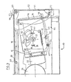
- the apparatus 10 comprises a housing 12 mounted on the main "U" shaped frame 14 (see Figure 5) having an open end 16 for receiving a removable magazine 18 for storing records R such as compact discs or cassettes.
- the housing 12 is mounted by means of bearing assemblies 20 to swivel about a horizontal axis 22 between a substantially horizontal operating, portion ( Figure 3) and a vertical loading position ( Figure 4), and adjacent the housing 12 is a playback/recording mechanism 24 of the information stored in the records R contained in the magazine 18.
- a transfer device for transferring a record R to and from the magazine 18 when the playback/recording mechanism is operating with the housing 12 and magazine 18 in the horizontal operating position.
- the playback/ recording mechanism 24 is also mounted for pivotal movement about an axis 26 which is parallel with the mounting axis 22 for the housing 12 and magazine 18and the playback/recording mechanism 24 and the housing 12 and magazine 18 are coupled and operated to produce coordinated opposite angular placements thereof about their respective axes 22, 26 between different fixed positions in each of which the playback/recording mechanism 24 is aligned with a different record R in the magazine 18 to allow transfer of the selected record therebetween by the transfer mechanism.
- One advantageous drive means for producting such-coordinated movement includes a drive gear 28 in engagement with a toothed sector 30 mounted on a plate 32 connected to the housing 12 and also in engagement with a toothed segment 34 mounted on the playback/ recording mechanism 24.
- a drive motor 36 connected to the drive gear 28 is operated to shift the magazine 18 and the playback/recording mechanism 24 about their respective axes 22, 26 between the different fixed positions in each of which the playback/recording mechanism 24 is aligned with a different record R in the magazine 18.
- the plate 32 is mounted to swivel about the mounting axis 22 of the housing 12 and is guided and limited in its swiveling movement by two pins 38, 40 carried by the plate 32 and associated with slots 39, 41 cut in the adjoining frame side panels of the apparatus case 44.
- means for coupling the housing 12 and the playback/ recording mechanism 24, shown in this embodiment as a coupling spring 46 resiliently holding the housing 12 in an operating position with respect to the plate 32 such that these components are integral and any angular movement of the plate 32 by the drive gear 28 results in an identical angular movement of the housing 12 and hence of the magazine 18.
- a lever 50 is provided which is mounted to pivot around a shaft 52 and is urged in a counterclockwise direction by a latch spring 54.
- the lever 50 has a claw end 56-adjacent the open end 16 of the housing 12 such that in the locking position of the lever 50 and the claw end 56 (illustrated in Figure 3), the magazine 18 is locked in the housing 12 when it is in the operating position.
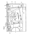
- a sliding cover 58 is fastened by a hinge 60 to an actuator plate 62 having a large rectangular opening 64, visible in Figure 5 which is a front view of the apparatus looking through the large rectangular opening 64 in the actuator plate 62 to the interior of the housing 12 which is pictured, in this view, with the magazine having been removed.
- the cover 58 blocks a top opening 66 in the top 68 of the case 44 of the apparatus through which access is provided to the housing 12 when it is in the vertical loading position.
- a handle 70 projects above the top 68 of the case 44 and is fastened to the. cover 58 and the actuator plate 62 at the hinge 60.
- FIGs 3 and 5 which depict the housing 12 in the substantially horizontal position (the operating position when a magazine 1*8 is present in the housing 12), it can be seen that the actuator plate 62 which is guided in an essentially vertical path from the position of Figure 3 to the position of Figure 4 and then pivots into a horizontal plane in which the large rectangular opening 64 in the actuator plate 62 is in register with the opening 66 in the top 68 of the case 44 of the apparatus 10.
- a magazine 18 may be inserted through the opening 66 in the top 68 of the case 44 and through the rectangular opening 64 in the actuator plate 62 into the open end 16 of the housing 12 and may be removed through the same registered openings.
- the sliding movement of the actuator plate 62 is guided by two pins 72, 74 ( Figure 5) passing through two symmetrical "Z" shaped 76 slots in the side panels of the case 44.
- the slots are "Z" shaped to produce the requisite vertical and swinging movement from the vertical to the horizontal plane of the actuator plate 62.
- the actuator plate 62 comes in contact with the side of the housing 12 adjacent the open end 16 as it is guided in its movement by the lower portion of the "Z" shaped slots 76, and causes the housing 12 to swivel about its mounting axis 22, the swiveling movement being guided by a projection 80 extending inwardly from the mounting plate 32 (as shown in Figures 3 and 5) and into a circular arc shaped slot 82 extending about 90° in the adjoining side wall of the housing 12.
- the coupling spring 46 is stretched between the plate 32 and the housing 12, this spring 46 providing a resilient connection to allow the swiveling movement.
- power Operated means including a micro-motor 86 and gears driving a toothed rack 88 connected to the cover 58 may be employed to move the cover 58, actuator plate 62, and housing 12 under power.
- Limit switches 90, 92 switch off the supply from a power source to the micro-motor 86 when the cover 58 has reached ist open and closed positions.
- a switch 94 located on top of the case 44 of the apparatus 10 which is connected to a control microprocessor 96, which is operated under program control to carry out the opening and closing sequences.
- the microprocessor 96 controls the motors and drives of the playback/recording mechanism 24 and transfer mechanism to return into the magazine 18 a disc present in the playback/recording mechanism 24, then actuates the micro-motor 86 for driving the cover 58 and housing 12 which causes the translation of the cover 58 and actuator plate 62, and swiveling of the housing 12 from the operating to the loading position.
- the supply to the motor 86 is maintained until the limit switch 90 is actuated; similarly, when closing the cover 58, the actuation of a second limit switch 92 switches off the power supply to the motor 86.
- FIG. 8-10 an alternative, most preferred, embodiment of the invention is illustrated.
- the housing 12, and hence magazine 18 is coupled to the playback/recording mechanism 24 by a rigid coupling.
- a rigid coupling avoids any problems that may occur with a resilient connection under conditions such as strong vibration, which may interfere with rapid, precise, relative positioning of the playback/recording mechanism 24 and magazine 18.
- the rigid coupling means between the playback/recording mechanism 24 and the housing 12, and hence the magazine 18, is provided by an elongated slider member 98 which is mounted for endwise sliding movement between the lateral side of the housing 12 and a plate 100 carried by said housing 12.
- the slider member 98 has a pair of openings 102, 104 cooperating with studs 105, 108 mounted on the housing 12 for guiding the translation of the slider member 98, and the slider member 98 is urged to the left as shown in Figure 13 by a spring 106 attached at one extremity to the slider member 98 and at its other extremity to the stud 108.
- the spring 106 urges the slider member 98 endwise such that a notch 110 in the projecting end of-the slider member 98 receives a stud 112 mounted on a wheel component 114 connected to the playback/recording mechanism 24.
- a central opening 116 in the slider member 98 provides clearance for the bearing assembly 20 on the mounting axis 22 of the housing 12 and allows the housing 12 and slider member 98 to swivel, as-shown in Figures 8 and 9.
- the coupling means is disengaged, the housing 12 and the magazine 1.8 are swiveled angularly, independent of the playback/ recording mechanism 24, to a loading position angularly displaced from the operating position shown in Figure 13 (in this case 45 degrees) .
- a cam drive is provided driven through gears 118 from a micro-motor 120 mounted on the frame 14.
- the cam drive includes a cam 122 driving a lever 124 having an arcuate profile 126 engaging a stud 128 mounted on the slider member 98 to translate the slider member 98 as the lever 124 is pivoted clockwise from the position shown in Figure 8.
- Such pivotal movement of the lever 124 causes the arcuate profile 126 thereof to engage the stud 128 on the slider member 98 and shifts the slider member to the right ( Figure 8), thus disengaging the notch 110 in the projecting end of the slider member 98 from the stud 112 on the playback/recording mechanism 24 (see Figure 9), and decoupling the housing 12 and magazine 18 from the playback/recording mechanism 24.
- the housing 12 and magazine 18 then swivel independently of the playback/recording mechanism 24, due to a drive gear 130 engaging a toothed segment 132 on the plate 100.
- Two limit switches 134, 136 are positioned to detect the angular position of the lever 124 and the slider member 98, respectively.
- the sliding cover 58 when the sliding cover 58 is opened, it actuates a sensing switch 90 which provides a signal to the microprocessor 96 of the control system.
- the microprocessor under program control causes power to be supplied to the micro-motor 86.
- both the gears 118 and the cam 122 are rotated and, simultaneously, the lever 124 is pivoted clockwise to drive the slider member 98 backwards and unclutch the notch 110 in its extremity from the stud 114 of the playback/recording mechanism 24, and the drive gear 130 and toothed segment 132 come in meshing connection so as to pivot the housing 12 and magazine 18 counterclockwise, to a loading position.
- the magazine locking lever 50 When-the housing has been pivoted about 45°, the magazine locking lever 50 abuts against the wall of an opening in the frame 14 so that any further pivoting of the housing 12 forces the lever 50 to pivot against the action of the latch spring 54 so as to disengage the claw end or catch 56 from the magazine 18 and allow removal of the magazine.
- a desired ultimate loading position is sensed by a switch which indicates to the microprocessor 96 the completion of the swiveling movement.
- a switch may also be employed in the housing 12 to sense the presence or absence of the magazine holder.
Landscapes
- Automatic Disk Changers (AREA)
Applications Claiming Priority (2)
| Application Number | Priority Date | Filing Date | Title |
|---|---|---|---|
| BE216592 | 1986-04-25 | ||
| BE0/216592A BE904681A (fr) | 1986-04-25 | 1986-04-25 | Appareil changeur de disques ou de cassettes. |
Publications (2)
| Publication Number | Publication Date |
|---|---|
| EP0243337A2 true EP0243337A2 (de) | 1987-10-28 |
| EP0243337A3 EP0243337A3 (de) | 1989-06-14 |
Family
ID=3844032
Family Applications (1)
| Application Number | Title | Priority Date | Filing Date |
|---|---|---|---|
| EP87870053A Withdrawn EP0243337A3 (de) | 1986-04-25 | 1987-04-22 | Plattenwechselgerät mit Ladung von oben |
Country Status (3)
| Country | Link |
|---|---|
| US (1) | US4833552A (de) |
| EP (1) | EP0243337A3 (de) |
| JP (1) | JPS62271246A (de) |
Families Citing this family (7)
| Publication number | Priority date | Publication date | Assignee | Title |
|---|---|---|---|---|
| BE1001702A6 (fr) * | 1988-06-03 | 1990-02-13 | Staar Dev Co Sa | Systeme de changeur automatique pour supports d'informations. |
| US4947273A (en) * | 1988-11-21 | 1990-08-07 | Texor Corporation | Autoloading, interchangeable-media, disk-drive apparatus |
| JPH0798923A (ja) * | 1993-09-29 | 1995-04-11 | Pioneer Electron Corp | ディスクチェンジャー |
| JP3424438B2 (ja) * | 1996-02-20 | 2003-07-07 | ティアック株式会社 | 記録媒体再生装置 |
| JPH10199093A (ja) * | 1996-12-27 | 1998-07-31 | Nakamichi Corp | チェンジャ−型ディスク再生装置 |
| US20050066343A1 (en) * | 2003-09-05 | 2005-03-24 | Hajime Mizuno | Recording medium transporting apparatus and disc changer apparatus |
| JP2005310212A (ja) * | 2004-04-16 | 2005-11-04 | Mitsubishi Electric Corp | ディスク装置 |
Family Cites Families (10)
| Publication number | Priority date | Publication date | Assignee | Title |
|---|---|---|---|---|
| GB1508972A (en) * | 1973-12-21 | 1978-04-26 | Black A | Sound reproducing apparatus |
| FR2331114A1 (fr) * | 1975-11-04 | 1977-06-03 | Luy Raphael | Distributeur de mini-disques souples |
| US4363044A (en) * | 1978-03-20 | 1982-12-07 | International Business Machines Corporation | Tray for magnetic disk drive machine |
| US4453188A (en) * | 1981-04-10 | 1984-06-05 | Amlyn Corporation | Disk drive |
| JPS58108057A (ja) * | 1981-12-18 | 1983-06-28 | Hitachi Ltd | デイスク自動装「てん」機構 |
| JPS58200458A (ja) * | 1982-05-19 | 1983-11-22 | Canon Inc | 記録又は再生装置 |
| US4504878A (en) * | 1982-09-08 | 1985-03-12 | Gutmann John W | System for storing and automatically retrieving recording discs |
| JPS61196461A (ja) * | 1985-02-25 | 1986-08-30 | Janome Sewing Mach Co Ltd | カセツト駆動装置のカセツト自動交換装置 |
| BE903223A (fr) * | 1985-09-12 | 1985-12-31 | Staar Sa | Appareil pour la reproduction et/ou l'enregistrement successif et/ou selectif de supports d'informations |
| BE904766R (fr) * | 1985-09-12 | 1986-09-01 | Staar Sa | Appareil pour la reproduction et/ou l'enregistrement successif et/ou selectif de supports d'informations. |
-
1987
- 1987-04-08 US US07/035,881 patent/US4833552A/en not_active Expired - Fee Related
- 1987-04-22 EP EP87870053A patent/EP0243337A3/de not_active Withdrawn
- 1987-04-23 JP JP62098769A patent/JPS62271246A/ja active Pending
Also Published As
| Publication number | Publication date |
|---|---|
| EP0243337A3 (de) | 1989-06-14 |
| US4833552A (en) | 1989-05-23 |
| JPS62271246A (ja) | 1987-11-25 |
Similar Documents
| Publication | Publication Date | Title |
|---|---|---|
| EP0243337A2 (de) | Plattenwechselgerät mit Ladung von oben | |
| GB2115205A (en) | Loading/unloading slot type disc player apparatus | |
| US6166877A (en) | Cassette auto changer system including tape signal reading means and selection means for selecting between a plurality of cassettes | |
| EP0533019A2 (de) | Lade- und Entladevorrichtung eines Plattenspielers | |
| JP3608866B2 (ja) | オートチェンジャー | |
| KR930008277B1 (ko) | 자기기록 재생장치의 카세트 장전기구 | |
| EP0519655B1 (de) | Plattenwechsler | |
| GB2189925A (en) | Cassette tape player | |
| US4918547A (en) | Door opening and closing mechanism for an automatic charger for recording media | |
| US5034832A (en) | Adaptor for a small-sized tape cassette | |
| JPH0325335Y2 (de) | ||
| EP0546531B1 (de) | Aufzeichnungs- und Wiedergabegerät | |
| JP3829222B2 (ja) | カートリッジおよび情報ディスク装置 | |
| JP3365955B2 (ja) | 記録媒体再生装置の記録媒体挿入口構造 | |
| JPH0664811B2 (ja) | カセツト装着装置 | |
| KR0141056B1 (ko) | 미니 디스크 플레이어 | |
| JP3180561B2 (ja) | ディスク装置 | |
| JP2714194B2 (ja) | 複数カセット装着装置 | |
| JPH0244377Y2 (de) | ||
| JPS6343653Y2 (de) | ||
| JPH0252342B2 (de) | ||
| JPH087914B2 (ja) | カセツト装着装置 | |
| JPH0477981B2 (de) | ||
| JP2571154B2 (ja) | ディスク交換式プレーヤ | |
| JP2000276822A (ja) | ローディング装置 |
Legal Events
| Date | Code | Title | Description |
|---|---|---|---|
| PUAI | Public reference made under article 153(3) epc to a published international application that has entered the european phase |
Free format text: ORIGINAL CODE: 0009012 |
|
| AK | Designated contracting states |
Kind code of ref document: A2 Designated state(s): BE CH DE FR GB IT LI NL |
|
| RAP3 | Party data changed (applicant data changed or rights of an application transferred) |
Owner name: STAAR SOCIETE ANONYME |
|
| PUAL | Search report despatched |
Free format text: ORIGINAL CODE: 0009013 |
|
| AK | Designated contracting states |
Kind code of ref document: A3 Designated state(s): BE CH DE FR GB IT LI NL |
|
| STAA | Information on the status of an ep patent application or granted ep patent |
Free format text: STATUS: THE APPLICATION IS DEEMED TO BE WITHDRAWN |
|
| 18D | Application deemed to be withdrawn |
Effective date: 19891215 |
|
| RIN1 | Information on inventor provided before grant (corrected) |
Inventor name: AGOSTINI, LOUIS PIERRE CESAR Inventor name: DENIS, PHILIPPE VICTOR |