EP0243535B1 - Méthode et appareil pour la production par charge d'eau-de-vie - Google Patents
Méthode et appareil pour la production par charge d'eau-de-vie Download PDFInfo
- Publication number
- EP0243535B1 EP0243535B1 EP86113721A EP86113721A EP0243535B1 EP 0243535 B1 EP0243535 B1 EP 0243535B1 EP 86113721 A EP86113721 A EP 86113721A EP 86113721 A EP86113721 A EP 86113721A EP 0243535 B1 EP0243535 B1 EP 0243535B1
- Authority
- EP
- European Patent Office
- Prior art keywords
- separator
- condenser
- container
- vapour
- line
- Prior art date
- Legal status (The legal status is an assumption and is not a legal conclusion. Google has not performed a legal analysis and makes no representation as to the accuracy of the status listed.)
- Expired - Lifetime
Links
- 238000000034 method Methods 0.000 title claims description 16
- 238000004519 manufacturing process Methods 0.000 title claims description 3
- 235000015096 spirit Nutrition 0.000 title claims 3
- XLYOFNOQVPJJNP-UHFFFAOYSA-N water Substances O XLYOFNOQVPJJNP-UHFFFAOYSA-N 0.000 claims description 18
- 238000004821 distillation Methods 0.000 claims description 13
- 238000001816 cooling Methods 0.000 claims description 9
- 230000009183 running Effects 0.000 claims description 7
- 230000000630 rising effect Effects 0.000 claims description 4
- 235000013399 edible fruits Nutrition 0.000 claims description 3
- 235000015203 fruit juice Nutrition 0.000 claims description 2
- LFQSCWFLJHTTHZ-UHFFFAOYSA-N Ethanol Chemical compound CCO LFQSCWFLJHTTHZ-UHFFFAOYSA-N 0.000 claims 3
- 230000015572 biosynthetic process Effects 0.000 claims 1
- 238000000746 purification Methods 0.000 claims 1
- 238000000926 separation method Methods 0.000 description 26
- 235000013532 brandy Nutrition 0.000 description 13
- 238000004140 cleaning Methods 0.000 description 6
- 238000002485 combustion reaction Methods 0.000 description 4
- 239000000470 constituent Substances 0.000 description 4
- 239000001760 fusel oil Substances 0.000 description 4
- 239000007788 liquid Substances 0.000 description 4
- JOYRKODLDBILNP-UHFFFAOYSA-N Ethyl urethane Chemical compound CCOC(N)=O JOYRKODLDBILNP-UHFFFAOYSA-N 0.000 description 3
- 238000010924 continuous production Methods 0.000 description 3
- 239000003344 environmental pollutant Substances 0.000 description 3
- 231100000719 pollutant Toxicity 0.000 description 3
- 239000000126 substance Substances 0.000 description 3
- 239000003990 capacitor Substances 0.000 description 2
- 239000000356 contaminant Substances 0.000 description 2
- 238000011109 contamination Methods 0.000 description 2
- 239000000498 cooling water Substances 0.000 description 2
- 230000035622 drinking Effects 0.000 description 2
- 239000011521 glass Substances 0.000 description 2
- 239000003921 oil Substances 0.000 description 2
- 238000005070 sampling Methods 0.000 description 2
- 238000005507 spraying Methods 0.000 description 2
- 238000010586 diagram Methods 0.000 description 1
- 125000001495 ethyl group Chemical group [H]C([H])([H])C([H])([H])* 0.000 description 1
- 238000001704 evaporation Methods 0.000 description 1
- 238000010304 firing Methods 0.000 description 1
- 230000007257 malfunction Effects 0.000 description 1
- 239000002244 precipitate Substances 0.000 description 1
- 239000000047 product Substances 0.000 description 1
- 239000002002 slurry Substances 0.000 description 1
- 239000004575 stone Substances 0.000 description 1
- 238000005406 washing Methods 0.000 description 1
Images



Classifications
-
- B—PERFORMING OPERATIONS; TRANSPORTING
- B01—PHYSICAL OR CHEMICAL PROCESSES OR APPARATUS IN GENERAL
- B01D—SEPARATION
- B01D3/00—Distillation or related exchange processes in which liquids are contacted with gaseous media, e.g. stripping
- B01D3/001—Processes specially adapted for distillation or rectification of fermented solutions
Definitions
- the invention relates to a process for the batch-wise production of brandy, in which fermented fruits or fruit juices are heated to produce raw steam, the raw steam is cleaned from fusel products in a separating section, preferably in the form of a distillation column, and condensed on a cooling surface, and the distillate's flow is deposited on a separate cooling surface and an apparatus for performing this method.
- Stone fruit distillates contain harmful ethyl carbamate (urethane). Ethyl carbamant distilled in the wake. However, it also occurs in the lead-up because ethyl carbamate contaminates raw spirit-carrying services and residual stocks are carried away with the following lead-in. Such contamination of the flow can be counteracted by washing the precipitates in question after each run. In practice, however, this only works poorly if you do not want to put up with intolerable expenses.
- the object of the invention is to design a method and a device of the type mentioned at the outset such that ethyl carbamate and other harmful substances with similar distillation behavior are kept as simple as possible from the finished distillate.
- the invention is characterized in that the distillate of each run is separated into three fractions which form the forerun, the middle run and the wake, each comprising the entire distillate obtained in an associated time period, and that the wake and wake on the one hand and the
- the middle run is condensed on separate cooling surfaces which are spatially separated from one another and can be shut off from one another on the inflow side by at least one shut-off device and are separately discharged.
- the desired pure distillate is then that obtained from the middle barrel.
- the pollutants contained in the wake are kept away from the distillate of the middle run.
- Those pollutants that have deposited in the piping system are carried away by the flow of the subsequent run and are also kept away from the distillate of the middle run by the special treatment of the flow. Since the fractions are separated from one another in terms of time, the size of the individual fractions can be determined by switching over from the forerunner to the middle run or from the middle run to the wake, thereby ensuring that the middle run is sufficiently free of the pollutants in question.
- the invention also relates to a device for extracting brandy from fermented distillation mash with a raw fire bladder for distilling the distillate, with a separator for cleaning the steam from fusel, which is connected to the raw fire bladder via a steam-promoting first spirit line, and with a condenser for condensing of the cleaned steam, which is connected to the separator via a second spirit line which promotes the cleaned steam.
- a further object of the invention is to design a device of this type in such a way that, with simple design effort and also with simple operation, corresponding to the method mentioned at the beginning, the harmful contaminants mentioned do not get into the finished brandy as far as possible.
- This object is achieved in that a raw fire condenser is provided and in that a changeover valve is provided in the first spirit line, via which this first spirit line can optionally be connected to the input side of the separator or the raw fire condenser.
- the lead and lag can be separated from the further processing to the brandy. It is particularly advantageous that the leading and trailing which contains the harmful substances do not get into the separator at all, so that no harmful substances can be separated out in the separator during the separation process, which can be taken up again by the middle run and then get into the brandy with the middle barrel.
- a condensate collector is provided which is connected to the output side of the condenser with the interposition of a distillation receiver, and that a lint collector is provided which is connected to the output side of the raw fire condenser with the interposition of a distillation receiver connected.
- the difficultly evaporating fusel oils are to be separated out in the separator.
- the upper part of the separator is designed as a continuous cooler, the condensate of which drips down.
- the separator becomes contaminated during operation and must be cleaned from time to time.
- Another object is to design a device of the type mentioned above so that the un desired fusel oils can be eliminated as completely as possible in a simple manner and that convenient cleaning is also possible.
- a first solution to this problem is characterized in that the separator is an elongated, upright, closed container, at the lower end of which there is an inlet for the steam and at the upper end of which an outlet for the cleaned steam is provided, that in the lower part of the container
- Several separation stages are provided one above the other that each separation stage has an annular shell which is open at the top and adjoins the wall of the container, and has a trough which extends only over the central cross-sectional part of the container and faces the open side and is arranged above the shell and with its lower edge dips into the bowl with play, so that between the inner edge of the bowl and the lower edge of the tub a labyrinth-like passage for the rising steam remains open, which can be shut off like a siphon by lint collecting in the bowl that for each separation stage is connected to an external pressure water pipe connectable shower head is provided, which extends centrally from below into the tub, and that a lockable, outwardly leading fusel drain is provided for each annular bowl, which leads
- a second solution to the stated problem which is preferably provided for simpler distilleries, in particular so-called settlement distilleries, is characterized in that the separator is an elongated, upright, closed container, at the lower part of which the inlet for the steam and at the upper end thereof a drain for the cleaned steam is provided that the top end of the container is a first free space that extends over the entire cross section of the container, that the lower part of the container is a second free space that extends over the entire cross section of the Container extends, and that at least in one of the free spaces a shower head is arranged, which can be connected to an external pressurized water line.
- the condensate collection container is a closed container which is equipped with an agitator, and that a steam outlet is provided on the top of the condensate collection container.
- 1 denotes a raw fire still, which is used for distilling distilled mash.
- 2 with a pre-separator is referred to, which is connected via a spirit pipe 3 to the raw fire bladder 1 and the separating line 4 leads back into the raw fire bladder 1.
- 5 denotes the first spirit line, which conveys the steam emanating from the raw fire bladder, which has passed the pre-separator, to a three-way valve 6.
- the first spirit line branches into a first branch 7 and a second branch 8.
- the first branch 7 opens at the top into a raw fire condenser 14, to which a lint collecting container 16 is connected at the bottom with the interposition of a distillation receiver 15.
- the second branch 8 opens into a separator 9 at the bottom.
- the second spirit line 10 leads from the separator 9 and leads to a capacitor 11.
- a condensate collector 13 is connected, while a distillation receiver 12 is kept.
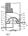
- the separator 9 is an elongated, upright, closed container 26, at whose lower end the inlet 17 and at the upper end of the outlet 18 is arranged.
- the lower part of the container has five separation stages 19 to 23 one above the other. A sight glass is provided for each of these separation stages.
- the separation stages are designed identically to one another, such as, for example, the separation stage 23, the configuration of which is now explained with reference to FIG.
- the separation stage 23 has an annular shell 25 which is open at the top and adjoins the container wall 24.
- a trough 27 which extends only over the central cross-sectional part of the container 26 and faces downward with the open side, is fastened in the container by means of fastening means, not shown.
- the tub 27 is arranged above the bowl 25 and dips with its lower edge 28 into the bowl 25 with play. Between the inner edge 29 of the bowl 25 and the lower edge 28 of the bowl 27 there is a labyrinth-like passage as indicated by the arrow 30 for the steam rising in the direction of arrow 31.
- This labyrinthine passage can be shut off siphon-like by fusel oil, which collects in the bowl 25 and whose level is indicated by the dash-dotted line 32, for example.
- a part of the tub 33 of the separation stage 22 can be seen under the separation stage 23.
- a shower head 35 which can be connected to an external pressurized water line 34 and extends centrally into the tub 27 from below, is provided for each separation stage.
- a lockable, outwardly leading fusel drain 36 which leads into the fusel collecting container 16, is provided for each of the annular shells, that is to say also for the shell 25.
- the separator is cleaned when a distillation run is finished.
- the valves 37 and 38 are opened and water is sprayed through the shower head 35 into the separation stage 23, which then flows out via the bowl 25 and the fusel drain 36 with the remaining fusel oil and the contaminants into the fusel collecting container 16.
- the upper part of the separator 9 is designed as a continuous cooler 39 with a system of vertical pipes 40 connected in parallel, through which the steam can flow upward to the outlet 18 in the direction of arrow 31.
- the pipes 40 are washed with cold water, so that very volatile constituents condense on the pipe walls and the condensate drips down into the uppermost separation stage 23.
- the condensate collection container 13 is a closed container which is equipped with an agitator 42.
- a steam outlet 43 is provided at the top of the condensate collection container.
- the steam outlet 43 has a vertical riser pipe 44, the upper end of which is bent downward in a U-shape and the free end 45 of which is immersed in an upwardly open container 46.
- a steam outlet opening 47 is provided at the top of the U-bend. The dirt accompanying the escaping steam collects in the container 46 and is collected for control purposes.
- the raw fire bladder is filled with fermented mash, approximately up to the mirror indicated by the dash-dotted line 58, and is heated. This filling with fermented mash is constantly maintained by refilling.
- the so-called vapor advance occurs. While this flow is being created, the slurry valve is in a position in which the branch 7 is connected to the first spirit line, so that the leading steam reaches the raw fire condenser 14, is condensed there and then reaches the lint collection container 16. From there, the fusel can be used for other purposes or subjected to distillation again.
- the three-way valve 6 is switched over as soon as the steam flowing in the first spirit line has a sufficient degree of purity.
- the steam in the first spirit line is increasingly polluted and this part of the spirit is called the wake that follows the middle run to be evaluated. This wake is kept away from the separator 9.
- the quality of the steam flowing in the first spirit line 5 is constantly monitored and as soon as contamination is found, the three-way valve is switched over again, so that the first spirit line is connected to the branch 7 and the wake, as well as the flow through the raw fire condenser 14, is condensed and then gets into the fuselage container 16.
- the raw edge bladder 1 is emptied, the system is cleaned and is then ready to process a new batch of stilling mash as described.
- the finished brandy collects in the condensate collector.
- Sampling taps are provided at various points in the system for required sampling, but these are not shown in the drawing.
- the exemplary embodiment shown in FIG. 4 is an exemplary embodiment which is greatly simplified compared to the exemplary embodiment according to FIGS. 1 to 3 and which is intended for very small distilleries.
- the raw fire bladder labeled 61 corresponds to the raw fire bladder 1 and is used to hold the fermented distillate and distill it.
- a first spirit line is designated, which conveys the steam emanating from the raw fire bladder to a three-way valve 66. In the three-way valve 66, the first spirit line branches into a first branch 67 and a second branch 68.
- the first branch 67 opens into a raw fire condenser 74, which corresponds to the raw fire condenser 14.
- a fusel collecting container can be connected at the bottom, optionally with the interposition of a distillation receiver, but it is also possible to simply place a fusel collecting container under the outlet 49 arranged below.
- 50 and 51 are Connections for a cooling water flow operated in counterflow.
- the second branch 68 opens into the lower part 53 of a separator 69, the function of which corresponds to that of the separator 9 from FIGS. 1 and 3.
- a pre-separator corresponding to the pre-separator 2 is not provided in this embodiment.
- the separator 69 is an elongated, upright, closed container, at the upper end of which the outlet 78 is provided for the cleaned steam.
- a first free space 54 is provided at the uppermost end of the separator 69 and extends over the entire cross section of the container.
- the lower part of the separator 69 takes up a second free space 55, which also extends over the entire cross section of the container.
- a shower head 56, 57 is arranged in each of the two free spaces and can be connected to an external pressurized water line 84.
- a continuous cooler 89 corresponding to the continuous cooler 39, which, like the continuous cooler 39, as shown in FIG. 2, consists of a plurality of riser pipes running in parallel and surrounded by cooling water.
- the lower end of the container 69 opens out via a funnel-shaped bottom part 60 into a return line 91 which leads into the raw fire bladder 61.
- the second spirit line 70 leads from the outlet 78, which leads to the condenser 71, which is constructed in exactly the same way as the condenser 11. At the bottom of the condenser 71, the condensate flows out via the outflow 100, which now, as in the exemplary embodiment according to FIG. 1 to 3 can be passed through a still to a condensate collector or otherwise collected.
- the operation is carried out in the same way as in the exemplary embodiment according to FIGS. 1 to 3.
- the three-way valve 66 is switched during the flow so that the first spirit line 65 is connected to the first branch 67 and the flow is condensed in the raw fire condenser.
- the three-way valve 65 has the same position during the overrun.
- the first spirit pipe 65 is connected to the second branch 68, so that the middle run is first cleaned in the separator 69 and then condensed in the condenser 71 to the brandy.
- the raw fire bladder is cleaned and can be refilled.
- the separator is cleaned by spraying cleaning water through the shower heads 56, 57. The cleaning water then flows into the raw fire bladder 61 and can be drained from there after cleaning the raw fire bladder.
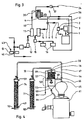
- 101 denotes the raw fire bladder on which a boiler hat 102 with sight glass 103 is seated.
- the first spirit line 104 leads from the top end of the boiler hat and leads to a three-way valve 105.
- a first branch 106 leads from the three-way valve to the raw fire condenser 107 and a second branch 108 to the separator 109.
- the second branch 108 opens into the separator at the lower end and from the upper end of the separator the second spirit line 110 leads to the condenser 111 leads.
- the condensed middle run can be removed as a highly pure drinking brandy.
- less pure condensate is obtained that can be used for other purposes or that can be returned to the raw fire still for further distillation.
- a water bath boiler is designated, with which the raw fire bladder 101 is heated in a water bath.
- the separator 109 is an elongated, upright, closed container, the upper part 115 of which has a flow cooler corresponding to the flow cooler 39.
- the lower part 114 of the container has a plurality of separation stages which correspond to the separation stages 19 to 23 from FIG. 1 and between which shower heads are arranged corresponding to the shower head 35 and which are connected to the outer pressure water line 116.
- the design of the separation stages differs from that of FIG. 1, as will be explained below with reference to FIG. 8.
- the separation stage 120 is shown excellent.
- the separation stage 120 consists of an annular, upwardly open shell 122 adjoining the container wall 121.
- a trough 123 which only extends over the central cross-sectional area of the container 121, is arranged with its open side facing downward over the shell 122 and that it is immersed with its lower edge 124 into the liquid filling 125 of the shell 122 like a siphon.
- a path corresponding to arrow 126 is formed for the steam rising from the bottom upwards through the siphon-like closure.
- an overflow pipe is designated that is open at the top and bottom and immersed in the liquid filling up to the liquid play 128, the separation stage 129 arranged underneath.
- the overflow pipe belonging to this next lower separation stage which corresponds to the overflow pipe 127, is arranged offset by a small angular amount in the circumference, so that it is not in the way of the overflow pipe 127. In this way, it is ensured that the entire overflow of the tub 123 runs through the overflow pipe into the next lower bowl and so on until the remaining overflow collects at the very bottom in the funnel-shaped bottom part 130 of the container 121. From there, a shutoff line 131 leads into the raw fire bladder 101.
- the tub 123 has a drain 133 which can be closed by a plug 132.
- the stopper can be raised from the outside using a handle 134 and the drawn closed position can be reset. In this way it is possible to let the liquid run out of the bowl 122 for cleaning purposes.
- shower heads 135, 136, 137 are arranged between the individual separation stages and can be connected to an external pressurized water line.
- a further shower head 140 is, as can be seen from FIG. 5, arranged at the uppermost end of the separator within the separator and connected to the same pressurized water line 138.
- the outer pressurized water line can be shut off by an adjustable valve 139.
- some pipes 141, 142 of the once-through cooler 143, which correspond to the pipes 40 from FIG. 2, are indicated. The system is operated accordingly, as described for the system from FIG. 1.
- the boiler hat is missing compared to FIG. 5, and instead the separator 150 is placed directly on the raw fire bladder 151.
- a first line 152 leads from the lower end of the separator and leads to a multi-way valve 153.
- a second line 154 extends from the upper end of the separator and leads to the same multi-way valve 153. From the multi-way valve 153, a line 155 goes to the raw fire cooler 156 and another line 157 to the condenser 158. During the flow and during the run-on, the multi-way valve 153 is switched from line 152 to line 155. Lines 154 and 157 are cordoned off. During the middle run, the valve is a flow connection between line 154 and line 157, while lines 152 and 155 are shut off. The spirit first reaches the bottom end of the separator and in the forward position of the multi-way valve, it leaves the separator immediately and flows via lines 152, 155 to the raw fire cooler 156.
- the separator 150 is designed as shown in FIG. 8 and described in the text relating to FIG.
- the shower heads are labeled 160 to 164 and a handle corresponding to the handle 134 is labeled 165.
- the pressurized water line for the shower heads is labeled 166.
- the exemplary embodiment according to FIG. 6 is designed in exactly the same way as that according to FIG. 5 and is also operated in the same way.
- a raw strip blister 180 corresponding to the raw fire bladder 1 is provided, from which a spirit line 181 leads to a pre-separator 182, from which a separation line 184 leads back into the raw fire bladder 180.
- the first spirit line 185 leads from the pre-separator 182 and leads to a three-way valve 186. From the three-way valve, a first branch 187 leads to a raw fire cooler 188 and a second branch 190 to a condenser 189. The flow and follow-up reach the raw fire cooler 188 by appropriate adjustment of the valve 186, while the middle run by correspondingly different adjustment of the valve 186 in the condenser 189 arrives.
- the drinking brandy resulting from the condenser 189 may not yet be sufficiently pure; it can then be distilled again in the same system in order to achieve a higher degree of purity which again keeps the flow and return from the condenser 189 by adjusting the valve 186 accordingly.
Landscapes
- Chemical & Material Sciences (AREA)
- Chemical Kinetics & Catalysis (AREA)
- Vaporization, Distillation, Condensation, Sublimation, And Cold Traps (AREA)
- Alcoholic Beverages (AREA)
Claims (10)
Priority Applications (2)
| Application Number | Priority Date | Filing Date | Title |
|---|---|---|---|
| AT86113721T ATE50592T1 (de) | 1986-04-29 | 1986-10-03 | Verfahren und vorrichtung zur chargenweisen gewinnung von branntwein. |
| DE8702149U DE8702149U1 (de) | 1986-04-29 | 1987-02-12 | Abscheider für eine Vorrichtung zum Gewinnen von Branntwein |
Applications Claiming Priority (4)
| Application Number | Priority Date | Filing Date | Title |
|---|---|---|---|
| LU86413 | 1986-04-29 | ||
| LU86413A LU86413A1 (de) | 1986-04-29 | 1986-04-29 | Verfahren zum gewinnen von branntwein aus vergorener brennmaische und vorrichtung zur ausuebung dieses verfahrens |
| LU86427A LU86427A1 (de) | 1986-05-13 | 1986-05-13 | Verfahren zum gewinnen von branntwein aus vergorener brennmaische und vorrichtung zur ausuebung dieses verfahrens |
| LU86427 | 1986-05-13 |
Publications (2)
| Publication Number | Publication Date |
|---|---|
| EP0243535A1 EP0243535A1 (fr) | 1987-11-04 |
| EP0243535B1 true EP0243535B1 (fr) | 1990-02-28 |
Family
ID=26640315
Family Applications (1)
| Application Number | Title | Priority Date | Filing Date |
|---|---|---|---|
| EP86113721A Expired - Lifetime EP0243535B1 (fr) | 1986-04-29 | 1986-10-03 | Méthode et appareil pour la production par charge d'eau-de-vie |
Country Status (4)
| Country | Link |
|---|---|
| EP (1) | EP0243535B1 (fr) |
| JP (1) | JPH082291B2 (fr) |
| CA (1) | CA1327540C (fr) |
| DE (1) | DE3669174D1 (fr) |
Families Citing this family (6)
| Publication number | Priority date | Publication date | Assignee | Title |
|---|---|---|---|---|
| DE8906105U1 (de) * | 1989-05-17 | 1989-07-06 | Kothe, Ulrich, 7332 Eislingen | Katalysatorvorrichtung für Brennereigeräte |
| ATE106939T1 (de) * | 1988-08-20 | 1994-06-15 | Ulrich Kothe | Verfahren und vorrichtung zur verringerung bzw. beseitigung von schadstoffen während der gewinnung von branntwein aus vornehmlich steinobst. |
| WO1993016168A1 (fr) * | 1992-02-14 | 1993-08-19 | Oy Alko Ab | Procede et appareil de production de whisky |
| JPH07503360A (ja) * | 1992-02-14 | 1995-04-13 | ジェーピーアイ プロセス コントラクティング オサケ ユキチュア | ウィスキーの製造方法および製造装置 |
| FR3071851B1 (fr) * | 2017-09-29 | 2019-10-18 | Martell & Co | Dispositif de distillation pour la production de spiritueux |
| CN115253338A (zh) * | 2022-07-15 | 2022-11-01 | 四川古蔺仙潭酒厂有限公司 | 一种自动蒸馏系统及自动蒸馏工艺 |
Family Cites Families (10)
| Publication number | Priority date | Publication date | Assignee | Title |
|---|---|---|---|---|
| FR766465A (fr) * | 1934-01-03 | 1934-06-28 | Procédé de préparation d'eau-de-vie et appareil permettant l'exécution de ce procédé | |
| FR1038520A (fr) * | 1951-06-19 | 1953-09-29 | Perfectionnements aux alambics | |
| DE1134966B (de) * | 1961-06-13 | 1962-08-23 | Kurt Rettberg | Als Dampfteiler ausgebildeter Aufsatz fuer Destillationskolonnen |
| FR1568336A (fr) * | 1968-03-29 | 1969-05-23 | ||
| DE1792097C3 (de) * | 1968-07-22 | 1973-09-13 | Arnold 7778 Markdorf Holstein | Verstarkereinnchtung fur Brennerei anlagen |
| FR2040682A5 (en) * | 1969-04-09 | 1971-01-22 | Bokobsa Albert | Brandy distillation process for instant - maturity |
| DE2311428C3 (de) * | 1973-03-08 | 1979-10-18 | Rudolf 7701 Muehlhausen Hohmann | Brennereivorrichtung |
| FR2312562A1 (fr) * | 1975-05-30 | 1976-12-24 | Audebeau Didier | Tete de separation des flegmes |
| FR2432547A1 (fr) * | 1978-07-31 | 1980-02-29 | Broustet Jean | Alambic perfectionne |
| DE3241493C2 (de) * | 1982-11-10 | 1984-08-30 | Gebr. Kisker oHG, 4802 Halle | Verfahren zur kontinuierlichen Gewinnung von gereinigtem Alkohol aus vergorener Maische |
-
1986
- 1986-10-03 DE DE8686113721T patent/DE3669174D1/de not_active Expired - Lifetime
- 1986-10-03 EP EP86113721A patent/EP0243535B1/fr not_active Expired - Lifetime
-
1987
- 1987-04-27 JP JP10416587A patent/JPH082291B2/ja not_active Expired - Lifetime
- 1987-04-28 CA CA000535751A patent/CA1327540C/fr not_active Expired - Fee Related
Also Published As
| Publication number | Publication date |
|---|---|
| JPH082291B2 (ja) | 1996-01-17 |
| EP0243535A1 (fr) | 1987-11-04 |
| DE3669174D1 (de) | 1990-04-05 |
| CA1327540C (fr) | 1994-03-08 |
| JPS62278976A (ja) | 1987-12-03 |
Similar Documents
| Publication | Publication Date | Title |
|---|---|---|
| EP0451721B1 (fr) | Procédé de nettoyage d'objets et appareil pour l'exécuter | |
| DE3818844C1 (fr) | ||
| DE2639836C3 (de) | Verfahren und Anordnung zur Reinigung oder Aufbereitung von Wasser | |
| DE69621456T2 (de) | Gerät zur entfernung unerwünschter, flüchtiger stoffe aus der bierwürze | |
| DE69114276T2 (de) | Ein verbessertes Verfahren zur Destillation/Deodorisierung von Ölen, Fetten und Fettsäuren. | |
| EP0196644A2 (fr) | Procédé et appareil de régénération de solutions aqueuses de nettoyage comprenant de l'huile et de la graisse | |
| EP0243535B1 (fr) | Méthode et appareil pour la production par charge d'eau-de-vie | |
| DE3341603A1 (de) | Verfahren und vorrichtungen zur verringerung des alkoholgehaltes von originalwein | |
| DE4123827C2 (de) | Verfahren zur Aufbereitung einer wässrigen Reinigungsflüssigkeit sowie Anlage zur Durchführung eines solchen Verfahrens | |
| DE834097C (de) | Dephlegmator zur Rueckflussdestillation von korrodierenden Fluessigkeiten, wie Schwefelsaeure | |
| LU86427A1 (de) | Verfahren zum gewinnen von branntwein aus vergorener brennmaische und vorrichtung zur ausuebung dieses verfahrens | |
| LU86413A1 (de) | Verfahren zum gewinnen von branntwein aus vergorener brennmaische und vorrichtung zur ausuebung dieses verfahrens | |
| DE3214064A1 (de) | Vorrichtung zum schwadenabzug an einer maische- und/oder wuerzepfanne | |
| DE8702149U1 (de) | Abscheider für eine Vorrichtung zum Gewinnen von Branntwein | |
| DE1493048A1 (de) | Verfahren zur Herstellung von Polyalkoholen und Einrichtungen zur Durchfuehrung des Verfahrens | |
| DE352432C (de) | Einrichtung zum Abdestillieren von Benzolkohlenwasserstoffen aus gesaettigtem Waschoel mit Hilfe von unmittelbar einwirkendem Wasserdampf | |
| DE2804592A1 (de) | Klaervorrichtung zum kontinuierlichen dekantieren | |
| DE3006127A1 (de) | Kontinuierlich arbeitende verdampferanlage fuer kontaminierte fluessigkeiten | |
| DE950150C (de) | Vorrichtung zum Reinigen von aus Samen oder Nuessen gewonnenen OElen oder Fetten | |
| DE1223805B (de) | Verfahren zur Beheizung von Schweroel- oder sonstigen hochviskosen Fluessigkeiten zwecks Ableitung aus Abscheidern | |
| DE737534C (de) | Verfahren und Vorrichtung zum Abscheiden und Waschen von Fuseloel bei Alkoholdestillier- und Rektifizierapparaten | |
| DE606133C (de) | Verfahren und Vorrichtung zur fraktionierten Destillation | |
| DE102018102512A1 (de) | Einrichtung zum Erzeugen von Dampf | |
| DE744815C (de) | Vorrichtung und Verfahren zum Destillieren, insbesondere von hochsiedenden Fluessigkeiten | |
| AT29470B (de) | Verfahren zur selbsttätigen Regelung des Spritaustritts aus dem oberen Teil von ununterbrochen arbeitenden Rektifikatoren oder auch aus deren Kondensatoren. |
Legal Events
| Date | Code | Title | Description |
|---|---|---|---|
| PUAI | Public reference made under article 153(3) epc to a published international application that has entered the european phase |
Free format text: ORIGINAL CODE: 0009012 |
|
| 17P | Request for examination filed |
Effective date: 19870518 |
|
| AK | Designated contracting states |
Kind code of ref document: A1 Designated state(s): AT BE CH DE ES FR GB GR IT LI LU NL SE |
|
| 17Q | First examination report despatched |
Effective date: 19880519 |
|
| GRAA | (expected) grant |
Free format text: ORIGINAL CODE: 0009210 |
|
| AK | Designated contracting states |
Kind code of ref document: B1 Designated state(s): AT BE CH DE ES FR GB GR IT LI LU NL SE |
|
| PG25 | Lapsed in a contracting state [announced via postgrant information from national office to epo] |
Ref country code: SE Effective date: 19900228 Ref country code: NL Effective date: 19900228 Ref country code: GR Free format text: LAPSE BECAUSE OF FAILURE TO SUBMIT A TRANSLATION OF THE DESCRIPTION OR TO PAY THE FEE WITHIN THE PRESCRIBED TIME-LIMIT Effective date: 19900228 Ref country code: GB Effective date: 19900228 |
|
| REF | Corresponds to: |
Ref document number: 50592 Country of ref document: AT Date of ref document: 19900315 Kind code of ref document: T |
|
| REF | Corresponds to: |
Ref document number: 3669174 Country of ref document: DE Date of ref document: 19900405 |
|
| ITF | It: translation for a ep patent filed | ||
| PG25 | Lapsed in a contracting state [announced via postgrant information from national office to epo] |
Ref country code: ES Free format text: LAPSE BECAUSE OF FAILURE TO SUBMIT A TRANSLATION OF THE DESCRIPTION OR TO PAY THE FEE WITHIN THE PRESCRIBED TIME-LIMIT Effective date: 19900608 |
|
| ET | Fr: translation filed | ||
| NLV1 | Nl: lapsed or annulled due to failure to fulfill the requirements of art. 29p and 29m of the patents act | ||
| GBV | Gb: ep patent (uk) treated as always having been void in accordance with gb section 77(7)/1977 [no translation filed] | ||
| PLBE | No opposition filed within time limit |
Free format text: ORIGINAL CODE: 0009261 |
|
| STAA | Information on the status of an ep patent application or granted ep patent |
Free format text: STATUS: NO OPPOSITION FILED WITHIN TIME LIMIT |
|
| 26N | No opposition filed | ||
| EPTA | Lu: last paid annual fee | ||
| PGFP | Annual fee paid to national office [announced via postgrant information from national office to epo] |
Ref country code: LU Payment date: 19941001 Year of fee payment: 9 |
|
| PGFP | Annual fee paid to national office [announced via postgrant information from national office to epo] |
Ref country code: FR Payment date: 19941007 Year of fee payment: 9 |
|
| PGFP | Annual fee paid to national office [announced via postgrant information from national office to epo] |
Ref country code: BE Payment date: 19941011 Year of fee payment: 9 Ref country code: AT Payment date: 19941011 Year of fee payment: 9 |
|
| ITPR | It: changes in ownership of a european patent |
Owner name: CESSIONE;GEBR. JOSEF UND MATTHAUS ZIEGLER GMBH |
|
| PGFP | Annual fee paid to national office [announced via postgrant information from national office to epo] |
Ref country code: CH Payment date: 19941111 Year of fee payment: 9 |
|
| REG | Reference to a national code |
Ref country code: CH Ref legal event code: PUE Owner name: GEBR. JOSEF UND MATTHAEUS ZIEGLER GMBH |
|
| PG25 | Lapsed in a contracting state [announced via postgrant information from national office to epo] |
Ref country code: LU Free format text: LAPSE BECAUSE OF NON-PAYMENT OF DUE FEES Effective date: 19951003 Ref country code: AT Effective date: 19951003 |
|
| PG25 | Lapsed in a contracting state [announced via postgrant information from national office to epo] |
Ref country code: LI Effective date: 19951031 Ref country code: CH Effective date: 19951031 Ref country code: BE Effective date: 19951031 |
|
| BERE | Be: lapsed |
Owner name: GEBR. JOSEF UND MATTHAUS ZIEGLER G.M.B.H. Effective date: 19951031 |
|
| REG | Reference to a national code |
Ref country code: CH Ref legal event code: PL |
|
| PG25 | Lapsed in a contracting state [announced via postgrant information from national office to epo] |
Ref country code: FR Effective date: 19960628 |
|
| REG | Reference to a national code |
Ref country code: FR Ref legal event code: ST |
|
| PGFP | Annual fee paid to national office [announced via postgrant information from national office to epo] |
Ref country code: DE Payment date: 20041022 Year of fee payment: 19 |
|
| PG25 | Lapsed in a contracting state [announced via postgrant information from national office to epo] |
Ref country code: IT Free format text: LAPSE BECAUSE OF NON-PAYMENT OF DUE FEES Effective date: 20051003 |
|
| PG25 | Lapsed in a contracting state [announced via postgrant information from national office to epo] |
Ref country code: DE Free format text: LAPSE BECAUSE OF NON-PAYMENT OF DUE FEES Effective date: 20060503 |