EP0243565A1 - Dispositif d'accumulation de fil de trame pour machine à tisser - Google Patents
Dispositif d'accumulation de fil de trame pour machine à tisser Download PDFInfo
- Publication number
- EP0243565A1 EP0243565A1 EP86810317A EP86810317A EP0243565A1 EP 0243565 A1 EP0243565 A1 EP 0243565A1 EP 86810317 A EP86810317 A EP 86810317A EP 86810317 A EP86810317 A EP 86810317A EP 0243565 A1 EP0243565 A1 EP 0243565A1
- Authority
- EP
- European Patent Office
- Prior art keywords
- weft
- thread
- winder
- supply
- speed
- Prior art date
- Legal status (The legal status is an assumption and is not a legal conclusion. Google has not performed a legal analysis and makes no representation as to the accuracy of the status listed.)
- Granted
Links
- 238000003780 insertion Methods 0.000 claims abstract description 37
- 230000037431 insertion Effects 0.000 claims abstract description 37
- 238000004804 winding Methods 0.000 claims abstract description 31
- 238000009941 weaving Methods 0.000 claims abstract description 24
- 238000000034 method Methods 0.000 claims description 17
- 239000000696 magnetic material Substances 0.000 claims description 2
- 238000012432 intermediate storage Methods 0.000 abstract 1
- 238000010586 diagram Methods 0.000 description 8
- 229910000831 Steel Inorganic materials 0.000 description 2
- 230000015572 biosynthetic process Effects 0.000 description 2
- 238000007654 immersion Methods 0.000 description 2
- 239000010959 steel Substances 0.000 description 2
- 230000001133 acceleration Effects 0.000 description 1
- 230000002730 additional effect Effects 0.000 description 1
- 230000033228 biological regulation Effects 0.000 description 1
- 230000000903 blocking effect Effects 0.000 description 1
- 239000003086 colorant Substances 0.000 description 1
- 230000003247 decreasing effect Effects 0.000 description 1
- 239000004744 fabric Substances 0.000 description 1
- 238000010304 firing Methods 0.000 description 1
- 230000006870 function Effects 0.000 description 1
- 230000005484 gravity Effects 0.000 description 1
- 230000002093 peripheral effect Effects 0.000 description 1
Images

Classifications
-
- D—TEXTILES; PAPER
- D03—WEAVING
- D03D—WOVEN FABRICS; METHODS OF WEAVING; LOOMS
- D03D47/00—Looms in which bulk supply of weft does not pass through shed, e.g. shuttleless looms, gripper shuttle looms, dummy shuttle looms
- D03D47/34—Handling the weft between bulk storage and weft-inserting means
- D03D47/36—Measuring and cutting the weft
- D03D47/361—Drum-type weft feeding devices
- D03D47/367—Monitoring yarn quantity on the drum
-
- D—TEXTILES; PAPER
- D03—WEAVING
- D03D—WOVEN FABRICS; METHODS OF WEAVING; LOOMS
- D03D47/00—Looms in which bulk supply of weft does not pass through shed, e.g. shuttleless looms, gripper shuttle looms, dummy shuttle looms
- D03D47/34—Handling the weft between bulk storage and weft-inserting means
- D03D47/36—Measuring and cutting the weft
- D03D47/361—Drum-type weft feeding devices
-
- D—TEXTILES; PAPER
- D03—WEAVING
- D03D—WOVEN FABRICS; METHODS OF WEAVING; LOOMS
- D03D47/00—Looms in which bulk supply of weft does not pass through shed, e.g. shuttleless looms, gripper shuttle looms, dummy shuttle looms
- D03D47/34—Handling the weft between bulk storage and weft-inserting means
- D03D47/36—Measuring and cutting the weft
- D03D47/361—Drum-type weft feeding devices
- D03D47/364—Yarn braking means acting on the drum
Definitions
- the invention relates to the working method of a weft thread storage device for presenting weft thread for entry into a weaving machine, weft thread being drawn off from a bobbin and temporarily stored on a drum in several turns in a first winding zone as a first supply by means of a winder and by means of a second winder in a second supply can be transferred in a second winding zone.
- a weft thread store which works according to this method is known from European patent application 0 145 163. He controls the end of the weft insertion by a thread stopper at the end of the second phase stopping the running of thread loops from a drum after a certain number of thread turns have been removed from the store. The drive for winding thread turns is controlled so that a certain number of thread turns for the weft insertion is provided.
- a weft thread storage device can measure the weft thread exactly, but its length can only be varied in steps corresponding to a circumferential length of the drum. The end of the weft entry will determined by the immersion of a finger on the circumference of the drum, whereby a tension spike emerges in the weft thread, since its braking is abruptly effected by the immersion.
- the speed of thread removal from the first supply is reduced before the end of the weft insertion according to a predetermined program.
- the speed of thread removal can be steadily reduced to zero or only reduced to a value that is low relative to the entry speed.
- the weft insertion is ended by blocking the thread feed to the weaving machine.
- the thread transfer from the first supply to the second supply can be carried out at a constant maximum thread speed, or the speed of the thread transfer is continuously increased to a value that results during the weft insertion into the weaving machine when the weft thread is used up shortly before the second supply is exhausted .
- the weft thread must be held behind the zone of the second supply formation in the discharge direction. The overall measured weft thread length is checked in the weaving machine after the entry, whereupon the run program for the second winder is adjusted in the event of a deviation from a target value.
- a weft thread store is used to carry out the method.
- At least the second winder is connected to a drive which is programmable with regard to the switch-on time and speed and which comprises a controlled electric motor and an associated control.
- the first winder can be driven independently of the second winder, it being only necessary to ensure that a certain thread supply in the first zone is not undershot.
- both winders can also be rigidly coupled to one another.
- the control of the drive of the second winder according to the described method enables gentle weft insertion, in particular the abrupt braking of the weft thread at the end of the insertion can be avoided, since the second winder can be operated towards the end of the weft insertion with a steadily decreasing angular velocity and the insertion speed of the weft thread is reduced in a controlled manner.
- the device is also suitable for the insertion of different weft threads on a weaving machine, since the second winder can be switched on in any weaving cycle. If several weft colors are entered, a corresponding number of thread stores must be arranged according to the invention.
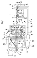
- a first winder 12 with a bearing 126 is freely rotatably mounted in the housing 11 of the weft thread store 1 and is driven by a drive 121, for example a frequency-controlled electric motor, via a drive belt 122.
- the drive 121 is controlled by the supply sensor 123 via the line 124. If a certain weft thread supply 21 is undershot, the drive 121 is switched on, so that the first winder 12 can pull weft thread 2 from a thread spool (not shown) and wind it up on the circumference of a drum 13 in a first winding zone 135.
- the drum 13 is mounted on the winder shaft 125 via bearings 131 and 132.
- a second winder 14 is rotatably arranged in the housing 11 by means of bearings 142. It can be set with a pulley 141 and a drive belt 143 by an electric motor 144 to rotate about the axis 10 of the weft thread store 1, the weft thread supply 21 being reduced, since the weft thread 2 passes through the eyelet 146 of the second winder 14 to a second winding zone 136 is relocated.
- the second winder operates until the end of the weft insertion, so that the pulling speed of the weft thread is smoothly decelerated to zero before the weft insertion is finished. To the right of the conical end 133 of the Drum 13 in Fig.
- a thread brake 16 is arranged with a conical axially displaceable against the drum 13 brake ring 161, which can be shifted towards the conical end with respect to the housing 162 by means of electromagnets 163 by means of electromagnets 163, whereby the weft thread in the region of conical end 133 is held.
- the brake In the dash-dotted position 161 ⁇ of the brake ring 161, the brake is closed.
- the thread brake 16 may only be switched on after the end of the rotary movement of the take-off winder 14 about the axis 10, since otherwise the weft thread jams between the eyelet 146 and the brake ring 161.
- the thread brake 16 must also be switched on by the second winder 14 before a new supply is formed in the second winding zone.
- the entry nozzle 36 Simultaneously with the start of withdrawal of the weft thread from the drum 13, the entry nozzle 36, which is fastened to the frame 35 of the weaving machine 3, is switched on and the weft thread is inserted into the shed 37 supported by nozzles 39 in the extended position. After the entry, the weft thread is struck on the edge of the fabric 38.
- a controller 15 which reads the angular position of the main shaft 31 of the weaving machine 3 by means of the reader 33 via the line 34.
- the controller 15 is connected via the line 145 to a controllable electric motor 144 which controls the second winder 14.
- the controller 15 has a connection to the sensors 41 to 43 on the catching side of the weaving machine via the lines 44 to 46.
- the sensors 41 to 43, which scan the position of the weft tip 22, are referred to as entry sensors 4.
- the controller 15 automatically increases the number of revolutions of the electric motor 144 due to this position of the weft thread tip 22, so that during the next or one of the next unwinding operations, more weft thread is drawn off from the weft thread supply 21 by means of the second winder 14 and accordingly the weft thread tip reaches the middle sensor 42 can. So that the regulation for the position of the weft thread tip is leveled out quickly after the entry to the sensor 42, a third sensor 43 can be arranged, which detects control deviations in the direction of an excessively long weft thread length.
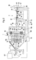
- the first and second winders are in alignment with one another.
- the first winder is held in the extended position as shown in FIG. 1.
- the second winder 14 then takes the dot-dash position 14 Stellung in FIG. 1.
- the weft thread 2 can then easily be threaded into the eyelet 146 of the second winder 14 from the outlet opening from the first winder 12.
- a certain thread supply 21 must then be formed by the winder 12 in the first winding zone 135, after which the second winder 14 can then also operate.
- the drum 13 is secured against rotation by an enlarged steel insert 134 which, due to its gravity, prevents the drum 13 from rotating without additional action by a magnet.
- FIG. 3a shows a drive 144 for the second winder 146, which is particularly low in mass.
- a ring 147 is embedded in the housing 11 and has electrical windings 148 distributed around the circumference.
- Magnetic fields are to be generated in the windings by means of the control 15 and the lines 145, which magnetic fields act on an insert 149a made of magnetic material in a rotor 149 which is guided in the ring 147.
- the magnetic fields thus exert acceleration or deceleration or supporting forces on the rotor 149.
- the eyelet 146 on the inside of the runner 149 unwinds 21 threads from the first thread supply.
- the rotor 149 takes the place of the second winder 14 and is driven in the same way.
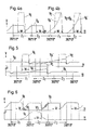
- V A means the removal speed of the weft thread from the first supply and is nothing else than the peripheral speed of the second winder, measured on the drum circumference.
- W the weft thread is inserted into the shed of the machine at the speed V E.
- Z1 or Z2 a thread transfer takes place from the first winding zone according to the speed profile V A.
- the weft insertion period is marked with W.
- the speed profile V E of the thread running through the nozzle 36 in the direction of the loom 3 corresponds in a first approximation to a rectangle.
- the steep increase in speed is brought about by the air supply to the nozzles 36, 39, while the sharp decrease in speed occurs towards the end of the entry period because the thread supply in the second winding zone 136 is scooped.
- the weft thread is then only entered into the shed 37 at the maximum discharge speed V A.
- the removal speed also begins to decrease according to the speed profile V A according to the predetermined program in the controller 15.
- the removal speed V A is only reduced to a certain value at the end of the weft thread entry according to the profile in FIG. 4a.
- the removal speed V A is immediately increased again to a maximum value, as a result of which the second winder 14 in turn begins to build up stocks in the second winding zone 136.
- 4b shows another possible operating mode for the weft thread store.
- the discharge speed V A ⁇ , or the winding speed of the second winder 14 is steadily increased from zero to a value close to the maximum entry speed of the weft thread into the shed 37, whereby the sudden drop in speed when the thread supply in the second winding zone 136 is exhausted is less than 4a is pronounced in the mode of operation.
- FIG. 5 shows the joint operation of two weft thread stores on a weaving machine in the so-called mixed change operation.
- the one memory according to the upper diagram in Fig. 5 provides weft thread in the weaving machine during the cycle Z1; thread is stored again during the cycle Z2 and at the beginning of the cycle Z3, whereupon weft thread is withdrawn again from the first memory in the cycle Z3.
- the end of the weft insertion coincides with the sudden drop in the thread removal speed V A at the end of a storage process.
- the second memory for which the discharge speed V A is shown in the lower diagram, stores during the cycle Z1 and releases during the cycle Z2 weft thread to only save again during the cycle Z3.
- the speed profiles V A and V A ⁇ correspond to those in FIGS. 4a and 4b, however, with the difference that in FIG. 5 the discharge speed V A is not reduced to zero at the end of the weft insertion.
- Fig. 6 shows the operation of two stores with selective thread withdrawal, that is, with controlled two-shot operation.
- the first weft store supplies Z1, Z3 etc. during the machine cycles, while the second weft store supplies Z2 thread according to the diagram below during the cycle.
- the storage of the weft thread extends over one cycle.
- the discharge speed V A of the first store according to the upper diagram in FIG. 6 is reduced towards the end of the weft insertion period W according to the above explanations to a low value at the end of the weft insertion. This is what the second winder 14 up to the machine rotation angle W 1.
- the dashed line in the upper diagram in FIG. 6 shows the speed curve when the weft yarn is removed in the first winding zone in the first store, even if Z2 thread would have to be supplied during the machine cycle. Because the winder 14 in the selected example continues to run up to the machine rotation angle W 1, the removal speed after switching on the second winder 14 from the machine rotation angle W 2 can be increased more slowly than when the winder is stopped at the end of the weft insertion period W.
- the second memory according to the diagram below in Fig. 6 is only for firing a shot during the cycle Z2 in operation.
- the speed profile V A for removing the weft yarn corresponds to the profile V A in the upper part of FIG. 6.
- Thread removal from the 1st weft supply by means of the winder 14, W begins only at the beginning of the weft insertion period. In this case, no second supply 23 is formed in the winding zone 136, since the weft thread is immediately removed into the shed 37. In this case, the winder 14 must be accelerated faster than in the other cases described, which requires a particularly low-mass drive 144. In order to achieve the required weft thread length during a weft insertion, the number of revolutions of the winder 14 must be checked by the controller 15 during each winding process.
Landscapes
- Engineering & Computer Science (AREA)
- Textile Engineering (AREA)
- Looms (AREA)
Applications Claiming Priority (2)
| Application Number | Priority Date | Filing Date | Title |
|---|---|---|---|
| CH1754/86 | 1986-04-29 | ||
| CH1754/86A CH669621A5 (fr) | 1986-04-29 | 1986-04-29 |
Publications (2)
| Publication Number | Publication Date |
|---|---|
| EP0243565A1 true EP0243565A1 (fr) | 1987-11-04 |
| EP0243565B1 EP0243565B1 (fr) | 1990-04-18 |
Family
ID=4217779
Family Applications (1)
| Application Number | Title | Priority Date | Filing Date |
|---|---|---|---|
| EP86810317A Expired - Lifetime EP0243565B1 (fr) | 1986-04-29 | 1986-07-15 | Dispositif d'accumulation de fil de trame pour machine à tisser |
Country Status (5)
| Country | Link |
|---|---|
| US (1) | US4799517A (fr) |
| EP (1) | EP0243565B1 (fr) |
| JP (1) | JPS62263350A (fr) |
| CH (1) | CH669621A5 (fr) |
| DE (1) | DE3670516D1 (fr) |
Cited By (8)
| Publication number | Priority date | Publication date | Assignee | Title |
|---|---|---|---|---|
| EP0330951A1 (fr) * | 1988-03-02 | 1989-09-06 | L.G.L. ELECTRONICS S.p.A. | Dispositif alimenteur de fil, en particulier pour métiers à tisser |
| WO1993023595A1 (fr) * | 1992-05-14 | 1993-11-25 | Te Strake B.V. | Dispositif de regulation de la course du fil entre un conditionnement fixe de fil et un dispositif consommateur de fil a fonctionnement periodique |
| WO1993025742A1 (fr) * | 1992-06-12 | 1993-12-23 | Iro Ab | Procede et dispositif d'alimentation en fils de trame |
| WO1995028348A1 (fr) * | 1994-04-13 | 1995-10-26 | Sobrevin Soc. De Brevets Industriels-Etablissement | Systeme de stockage de fil avec frein d'etirage du fil |
| US5546994A (en) * | 1994-10-14 | 1996-08-20 | Sobrevin Societe De Brevets Industriels-Etablissement | Thread storage drum with frustoconical brake strip |
| WO1997037069A1 (fr) * | 1996-04-01 | 1997-10-09 | Iro Ab | Frein a disque axial et appareil d'alimentation en fil equipe d'un tel frein |
| EP0707102A3 (fr) * | 1994-10-10 | 1998-05-27 | L.G.L. ELECTRONICS S.p.A. | Frein de fil positif modulé pour fournisseurs de trame |
| DE19839272B4 (de) * | 1997-09-11 | 2007-02-01 | Iro Sweden Ab | Steuerbare Fadenbremse |
Families Citing this family (7)
| Publication number | Priority date | Publication date | Assignee | Title |
|---|---|---|---|---|
| BE1001188A3 (nl) * | 1987-11-12 | 1989-08-08 | Picanol Nv | Werkwijze voor het regelen van de toevoer van inslagdraad bij weefmachines en inrichting die deze werkwijze toepast. |
| IT1217339B (it) * | 1988-02-11 | 1990-03-22 | Roy Electrotex Spa | Alimentatore di filo per macchine tessili |
| EP0519970B1 (fr) | 1990-03-12 | 1998-09-23 | Iro Ab | Frein de sortie de fil |
| US5261586A (en) * | 1992-03-26 | 1993-11-16 | Chen Jen Fu | Yarn feeding device with a guiding flange |
| US5669245A (en) * | 1996-03-08 | 1997-09-23 | Shieh; Meei-Ju | Yarn feeding device of a circular knitting machine |
| IT201700113434A1 (it) * | 2017-10-10 | 2019-04-10 | Lgl Electronics Spa | Metodo di controllo del consumo di filato in un processo di tessitura |
| CN109455574A (zh) * | 2018-12-05 | 2019-03-12 | 大连英蕴科技有限公司 | 一种海洋工程用线缆回收设备及方法 |
Citations (4)
| Publication number | Priority date | Publication date | Assignee | Title |
|---|---|---|---|---|
| DD143592A5 (de) * | 1978-05-18 | 1980-09-03 | Iro Ab | Fadenspeicher-und-liefervorrichtung |
| WO1983000137A1 (fr) * | 1981-07-14 | 1983-01-20 | Bonas Machine Co | Dispositif de mesure du fil de trame |
| GB2126610A (en) * | 1979-08-06 | 1984-03-28 | Leesona Holdings Inc | Method and apparatus for strand delivery |
| EP0145163A1 (fr) * | 1983-10-15 | 1985-06-19 | Sulzer Brothers Limited | Dispositif de mesure de la longueur de fils |
Family Cites Families (2)
| Publication number | Priority date | Publication date | Assignee | Title |
|---|---|---|---|---|
| JPS5891849A (ja) * | 1981-11-25 | 1983-05-31 | 株式会社豊田中央研究所 | ジエツトル−ム用緯糸貯留装置 |
| US4627474A (en) * | 1982-09-03 | 1986-12-09 | Aktiebolaget Iro | Yarn storing, feeding and measuring device |
-
1986
- 1986-04-29 CH CH1754/86A patent/CH669621A5/de not_active IP Right Cessation
- 1986-07-15 EP EP86810317A patent/EP0243565B1/fr not_active Expired - Lifetime
- 1986-07-15 DE DE8686810317T patent/DE3670516D1/de not_active Expired - Lifetime
-
1987
- 1987-04-22 US US07/041,097 patent/US4799517A/en not_active Expired - Fee Related
- 1987-04-28 JP JP62103474A patent/JPS62263350A/ja active Pending
Patent Citations (4)
| Publication number | Priority date | Publication date | Assignee | Title |
|---|---|---|---|---|
| DD143592A5 (de) * | 1978-05-18 | 1980-09-03 | Iro Ab | Fadenspeicher-und-liefervorrichtung |
| GB2126610A (en) * | 1979-08-06 | 1984-03-28 | Leesona Holdings Inc | Method and apparatus for strand delivery |
| WO1983000137A1 (fr) * | 1981-07-14 | 1983-01-20 | Bonas Machine Co | Dispositif de mesure du fil de trame |
| EP0145163A1 (fr) * | 1983-10-15 | 1985-06-19 | Sulzer Brothers Limited | Dispositif de mesure de la longueur de fils |
Cited By (11)
| Publication number | Priority date | Publication date | Assignee | Title |
|---|---|---|---|---|
| EP0330951A1 (fr) * | 1988-03-02 | 1989-09-06 | L.G.L. ELECTRONICS S.p.A. | Dispositif alimenteur de fil, en particulier pour métiers à tisser |
| WO1993023595A1 (fr) * | 1992-05-14 | 1993-11-25 | Te Strake B.V. | Dispositif de regulation de la course du fil entre un conditionnement fixe de fil et un dispositif consommateur de fil a fonctionnement periodique |
| WO1993025742A1 (fr) * | 1992-06-12 | 1993-12-23 | Iro Ab | Procede et dispositif d'alimentation en fils de trame |
| US5509450A (en) * | 1992-06-12 | 1996-04-23 | Iro Ab | Weft yarn feeding device having a rotating retainer |
| WO1995028348A1 (fr) * | 1994-04-13 | 1995-10-26 | Sobrevin Soc. De Brevets Industriels-Etablissement | Systeme de stockage de fil avec frein d'etirage du fil |
| CN1063722C (zh) * | 1994-04-13 | 2001-03-28 | 专利工业建设协会 | 具有纱线退绕制动器的纱线存放器 |
| EP0707102A3 (fr) * | 1994-10-10 | 1998-05-27 | L.G.L. ELECTRONICS S.p.A. | Frein de fil positif modulé pour fournisseurs de trame |
| US5546994A (en) * | 1994-10-14 | 1996-08-20 | Sobrevin Societe De Brevets Industriels-Etablissement | Thread storage drum with frustoconical brake strip |
| WO1997037069A1 (fr) * | 1996-04-01 | 1997-10-09 | Iro Ab | Frein a disque axial et appareil d'alimentation en fil equipe d'un tel frein |
| US6257516B1 (en) | 1996-04-01 | 2001-07-10 | Iro Ab | Axial disc brake and yarn feeding device including an axial disc brake |
| DE19839272B4 (de) * | 1997-09-11 | 2007-02-01 | Iro Sweden Ab | Steuerbare Fadenbremse |
Also Published As
| Publication number | Publication date |
|---|---|
| US4799517A (en) | 1989-01-24 |
| JPS62263350A (ja) | 1987-11-16 |
| DE3670516D1 (de) | 1990-05-23 |
| CH669621A5 (fr) | 1989-03-31 |
| EP0243565B1 (fr) | 1990-04-18 |
Similar Documents
| Publication | Publication Date | Title |
|---|---|---|
| EP0243565B1 (fr) | Dispositif d'accumulation de fil de trame pour machine à tisser | |
| EP0094483B1 (fr) | Commande de broche de bobinage | |
| EP0237892A1 (fr) | Procédé et dispositif pour rebobiner des fils | |
| DE3238376C2 (de) | Fadenspeicher | |
| DE2328828A1 (de) | Aufwickelvorrichtung | |
| EP0777003A2 (fr) | Mécanisme rotatif pour lisières pas de gaze pour métiers à tisser | |
| EP1859089A1 (fr) | Dispositif d'introduction de fils de trame pour des machines de tissage, en particulier des machines de tissage a navette centrale | |
| EP0521816B1 (fr) | Procédé pour transferer le fil d'une bobine pleine à une bobine vide et un bobinoir | |
| DE4116497B4 (de) | Fadenliefervorrichtung | |
| DE102007038871A1 (de) | Verfahren zum Anspinnen an Textilmaschinen mit einer Mehrzahl von Spinnstellen | |
| CH381622A (de) | Webmaschine | |
| DD143592A5 (de) | Fadenspeicher-und-liefervorrichtung | |
| EP0451176B1 (fr) | Dispositif de livraison du fil | |
| DE3324947C1 (de) | Fadenspeichervorrichtung für Webmaschinen und Verfahren zu deren Betrieb | |
| DE1063537B (de) | Vorrichtung zum periodischen Abwickeln und Abmessen gleicher Laengen des Schussfadens fuer Webmaschinen mit Entnahme des Schussfadens von feststehenden Spulen | |
| EP0799915A2 (fr) | Procédé et appareil pour la régulation de ruban dans une machine de cardage | |
| DE10010196A1 (de) | Verfahren und Vorrichtung zum pneumatischen Halten eines Fadens | |
| DE4214734C2 (de) | Verfahren und Vorrichtung zum Anspinnen einer Offenend-Spinnvorrichtung | |
| DE3909106A1 (de) | Aufspulmaschine | |
| EP1254066A1 (fr) | Procede de livraison d'un fil sans torsion et dispositif livreur de fil | |
| DE3440389C1 (de) | Fadenspeichervorrichtung fuer Webmaschinen und Verfahren zu deren Betrieb | |
| WO1987000214A1 (fr) | Procede et dispositif pour relier les fils sur une installation de filage open-end a friction | |
| DE4423205A1 (de) | Aufspulmaschine | |
| EP0438439B1 (fr) | Dispositif de stockage et de livraison du fil | |
| DE1535643C2 (de) | Schußfaden Zwischenspeicher fur Webmaschinen mit feststehender Schuß faden Vorratsspule |
Legal Events
| Date | Code | Title | Description |
|---|---|---|---|
| PUAI | Public reference made under article 153(3) epc to a published international application that has entered the european phase |
Free format text: ORIGINAL CODE: 0009012 |
|
| 17P | Request for examination filed |
Effective date: 19860717 |
|
| AK | Designated contracting states |
Kind code of ref document: A1 Designated state(s): AT BE CH DE FR GB IT LI LU NL SE |
|
| RBV | Designated contracting states (corrected) |
Designated state(s): BE DE FR GB IT SE |
|
| 17Q | First examination report despatched |
Effective date: 19890127 |
|
| ITF | It: translation for a ep patent filed | ||
| GRAA | (expected) grant |
Free format text: ORIGINAL CODE: 0009210 |
|
| AK | Designated contracting states |
Kind code of ref document: B1 Designated state(s): BE DE FR GB IT SE |
|
| REF | Corresponds to: |
Ref document number: 3670516 Country of ref document: DE Date of ref document: 19900523 |
|
| GBT | Gb: translation of ep patent filed (gb section 77(6)(a)/1977) | ||
| ET | Fr: translation filed | ||
| PGFP | Annual fee paid to national office [announced via postgrant information from national office to epo] |
Ref country code: GB Payment date: 19900704 Year of fee payment: 5 |
|
| PGFP | Annual fee paid to national office [announced via postgrant information from national office to epo] |
Ref country code: FR Payment date: 19900717 Year of fee payment: 5 |
|
| PGFP | Annual fee paid to national office [announced via postgrant information from national office to epo] |
Ref country code: SE Payment date: 19900718 Year of fee payment: 5 |
|
| PGFP | Annual fee paid to national office [announced via postgrant information from national office to epo] |
Ref country code: DE Payment date: 19900731 Year of fee payment: 5 |
|
| PGFP | Annual fee paid to national office [announced via postgrant information from national office to epo] |
Ref country code: BE Payment date: 19900808 Year of fee payment: 5 |
|
| PLBE | No opposition filed within time limit |
Free format text: ORIGINAL CODE: 0009261 |
|
| STAA | Information on the status of an ep patent application or granted ep patent |
Free format text: STATUS: NO OPPOSITION FILED WITHIN TIME LIMIT |
|
| 26N | No opposition filed | ||
| PG25 | Lapsed in a contracting state [announced via postgrant information from national office to epo] |
Ref country code: GB Effective date: 19910715 |
|
| PG25 | Lapsed in a contracting state [announced via postgrant information from national office to epo] |
Ref country code: SE Effective date: 19910716 |
|
| ITTA | It: last paid annual fee | ||
| PG25 | Lapsed in a contracting state [announced via postgrant information from national office to epo] |
Ref country code: BE Effective date: 19910731 |
|
| BERE | Be: lapsed |
Owner name: GEBRUDER SULZER A.G. Effective date: 19910731 |
|
| GBPC | Gb: european patent ceased through non-payment of renewal fee | ||
| PG25 | Lapsed in a contracting state [announced via postgrant information from national office to epo] |
Ref country code: FR Effective date: 19920331 |
|
| PG25 | Lapsed in a contracting state [announced via postgrant information from national office to epo] |
Ref country code: DE Effective date: 19920401 |
|
| REG | Reference to a national code |
Ref country code: FR Ref legal event code: ST |
|
| EUG | Se: european patent has lapsed |
Ref document number: 86810317.7 Effective date: 19920210 |
|
| PG25 | Lapsed in a contracting state [announced via postgrant information from national office to epo] |
Ref country code: IT Free format text: LAPSE BECAUSE OF NON-PAYMENT OF DUE FEES;WARNING: LAPSES OF ITALIAN PATENTS WITH EFFECTIVE DATE BEFORE 2007 MAY HAVE OCCURRED AT ANY TIME BEFORE 2007. THE CORRECT EFFECTIVE DATE MAY BE DIFFERENT FROM THE ONE RECORDED. Effective date: 20050715 |