EP0243711A2 - Tool changing device - Google Patents
Tool changing device Download PDFInfo
- Publication number
- EP0243711A2 EP0243711A2 EP87104822A EP87104822A EP0243711A2 EP 0243711 A2 EP0243711 A2 EP 0243711A2 EP 87104822 A EP87104822 A EP 87104822A EP 87104822 A EP87104822 A EP 87104822A EP 0243711 A2 EP0243711 A2 EP 0243711A2
- Authority
- EP
- European Patent Office
- Prior art keywords
- tool
- spindle
- vertical
- horizontal
- headstock
- Prior art date
- Legal status (The legal status is an assumption and is not a legal conclusion. Google has not performed a legal analysis and makes no representation as to the accuracy of the status listed.)
- Withdrawn
Links
- 238000003801 milling Methods 0.000 claims abstract description 21
- 230000032258 transport Effects 0.000 claims abstract 2
- 230000033001 locomotion Effects 0.000 description 12
- 238000003754 machining Methods 0.000 description 6
- 238000000034 method Methods 0.000 description 5
- 238000009434 installation Methods 0.000 description 4
- SGTNSNPWRIOYBX-UHFFFAOYSA-N 2-(3,4-dimethoxyphenyl)-5-{[2-(3,4-dimethoxyphenyl)ethyl](methyl)amino}-2-(propan-2-yl)pentanenitrile Chemical compound C1=C(OC)C(OC)=CC=C1CCN(C)CCCC(C#N)(C(C)C)C1=CC=C(OC)C(OC)=C1 SGTNSNPWRIOYBX-UHFFFAOYSA-N 0.000 description 1
- 230000005540 biological transmission Effects 0.000 description 1
- 238000010276 construction Methods 0.000 description 1
- 238000003780 insertion Methods 0.000 description 1
- 230000037431 insertion Effects 0.000 description 1
- 125000006850 spacer group Chemical group 0.000 description 1
Images

Classifications
-
- B—PERFORMING OPERATIONS; TRANSPORTING
- B23—MACHINE TOOLS; METAL-WORKING NOT OTHERWISE PROVIDED FOR
- B23Q—DETAILS, COMPONENTS, OR ACCESSORIES FOR MACHINE TOOLS, e.g. ARRANGEMENTS FOR COPYING OR CONTROLLING; MACHINE TOOLS IN GENERAL CHARACTERISED BY THE CONSTRUCTION OF PARTICULAR DETAILS OR COMPONENTS; COMBINATIONS OR ASSOCIATIONS OF METAL-WORKING MACHINES, NOT DIRECTED TO A PARTICULAR RESULT
- B23Q3/00—Devices holding, supporting, or positioning work or tools, of a kind normally removable from the machine
- B23Q3/155—Arrangements for automatic insertion or removal of tools, e.g. combined with manual handling
- B23Q3/157—Arrangements for automatic insertion or removal of tools, e.g. combined with manual handling of rotary tools
- B23Q3/1578—Arrangements for automatic insertion or removal of tools, e.g. combined with manual handling of rotary tools for tool transfer in a machine tool with a horizontal and a vertical spindle; for tool transfer in a machine tool with a spindle having variable orientation
Definitions
- the invention relates to a tool changing device of the type specified in the preamble of claim 1, with which the tools of the vertical spindle and those of the horizontal spindle can be changed as required and according to the respective control or machining program without manual intervention and transferred to the tool magazine.
- a particular advantage of universal milling machines is that the workpieces can be machined one after the other with the horizontal spindle and the vertical spindle, the operations for changing the work spindles in modern machines, e.g. B. in so-called. Machining centers are automated.
- the universal processing too complicated workpieces in a single setup increases machining accuracy and reduces dead times.
- the program-controlled change of the tools for the horizontal spindle and the vertical spindle by means of a conventional tool changer, e.g. B. according to DE-OS 33 44 084. Due to the mutually perpendicular alignment of the two spindles, the transfer link of the tool changer must be able to perform motions about several axes by motor in order to remove the tools from the magazine and optionally to operate either the horizontal spindle or the vertical spindle. When the machine is at a standstill, the tool changer has to travel relatively long distances made up of different movements, which increases the changeover times and thus reduces the machine performance.
- the object of the invention is to provide a tool changing device which is suitable for the optional operation of the horizontal spindle and the vertical spindle of a universal milling machine and which accelerates the installation and removal of the tools in and made possible from the respective work spindle with a reduced overall technical outlay and thus reduced machine tool idle times.
- the total changeover times are shortened to the ultimately only essential installation and removal processes of the tools in and out of the respective work spindle, because the processes necessary for the supply and removal of the tools are by means of of the universally movable tool changer - not as before with the machine stopped - but with the machine working.
- the entire change processes are thus divided, with only the short-term installation and removal processes taking place when the work spindle is shut down, while the far longer part of the processes, such as removing the tools from the magazine, transporting them and aligning them in a predetermined transfer position , with the machine running.
- the tool changer specified in the subclaims offers the advantage that the tool magazine can be positioned relatively far back on the stand of the milling machine or - as a separate structural unit - can be positioned at a freely selectable location.
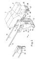
- the drawing shows a headstock 1 one Milling machine that carries a vertical milling head 2 via spacers 3 on its front end.
- the work spindle is mounted in the vertical milling head 2 and is driven in a conventional manner by an electric motor mounted on the headstock 1 via a brake transmission, a dog clutch and at least one bevel gear pair.
- clamping means are provided in the work spindle for releasably gripping and fixing a tool cone.
- a quick coupler 4 is integrated, which contains a pin 6 rotatably and axially displaceably mounted axially parallel to the spindle axis 5 in the milling head 2 and a support member fastened to its lower end in the form of a rectangular plate 7.
- two semicircular cutouts 8, 9 are provided offset from one another by 180 ° on both sides of the bolt 6, the size and shape of which is designed to accommodate a tool cone 10 each.
- spring pliers - not shown - are provided in the area of these cutouts 8, 9, which grip a tool cone and hold it in the support plate 7 during a changing operation.
- the quick coupler 4 is also assigned a rotary drive for controlled rotation by 180 ° and a feed drive for the axial extension and insertion movement of the bolt 6, both of which are integrated in the vertical milling head 2.
- a univer Seller tool changer 11 is provided, which is designed for operating the horizontal spindle and the vertical spindle.
- a support slide 13 is in the direction of the double arrow by means of a - not shown - linear drive, for. B. a spindle drive or a pressure cylinder, guided.
- a vertical support piece 14 is fixedly mounted on the slide 13, in whose lower end part a pivot pin 15 is mounted, which is rotated by a motor 16.
- a pivot lever 17 is wedged onto the free end section of the pivot pin 15, in the free end part of which a pivot pin 18 is mounted in a transverse bore.
- the tool changer 11 is in a retracted position in which its movable parts cannot interfere with the various machining operations.
- the quick coupler 4 is also retracted, so that the support plate 7 in the position shown in solid lines lies approximately on the lower end face of the vertical milling head 2.
- the linear motor for the quick coupler 4 is then actuated by the program control of the milling machine, which moves the bolt 6 and the support member 7 into the position shown in broken lines.
- the collet Since the collet has previously released the tool cone in the work spindle, it is taken away by the support member 7 and its spring elements.
- the quick coupler 4 is then rotated about the axis of the bolt 6, so that the tool cone held in the cutout 8 reaches a position to the side of the vertical milling head 2.
- the part of the support member 7 having the cutout 9 comes into the axial position of the work spindle.
- a new tool cone previously introduced into this cutout 9 is thus in the spindle axis and is inserted into the work spindle by a pulling-in movement caused by the linear drive of the quick coupler 4 and then fixed by actuating its collet.
- the tool located in the cutout 9 on the side next to the vertical milling head 2 is gripped by a pivoting movement of the swivel arm 20 caused by the motor 18 by its - empty - tool holder 21 and is pulled out of the cutout 9 of the support element 7 when it swings back.
- the carriage 13 moves back so far that the removed tool is transferred into a receptacle predetermined by the program in the chain magazine.
- a further tool is removed from the chain magazine 22 by means of the holder 21 and brought into a ready position, from which it can be removed within a very short time, e.g. B. still during the machining process or during the shutdown of the work spindle to which - then empty - cutout 8 of the support element 7 can be transferred. This completes a tool change that is repeated as often as required.
- a quick coupler 40 of the same construction which is built directly into the headstock 1 is assigned.
- This quick coupler 40 contains an axially parallel to the spindle axis of the horizontal spindle in the headstock 1 pivot pin 46, which - with the help of - not shown - drive motors can perform rotary movements by 180 ° and axial movements.
- a plate-shaped support element 47 is fastened, which contains two axially symmetrically arranged tool holders 48, 49 in the form of semicircular cutouts and spring elements.
- the pivot lever 17 is in the position shown in FIG. 2 by the motor 16 pivoted so that the swivel arm 20 can move the tool 10 into the receptacle 49 or remove it from it by moving about the axis of the bolt 19.
Landscapes
- Engineering & Computer Science (AREA)
- Mechanical Engineering (AREA)
- Automatic Tool Replacement In Machine Tools (AREA)
Abstract
Gegenstand der Erfindung ist eine Vorrichtung für den Werkzeugwechsel der Horizontal- und Vertikalspindel einer Universal-Fräsmaschine, bestehend aus einem Werkzeugmagazin (22) und aus einem Werkzeugwechsler (11), der die Werkzeuge vom Magazin übernimmt und sie wahlweise zur Vertikal- oder Horizontalspindel transportiert. Erfindungsgemäß ist der Vertikalspindel und der Horizontalspindel je ein Schnellwechsler (4) zugeordnet, der einen motorisch verdrehbar und axial verschiebbar parallel zur jeweiligen Spindelachse im Vertikal-Fräskopf (2) und im Spindelstock (1) angeordneten Drehbolzen (6) und ein vor der jeweiligen Spindel angeordnetes Tragelement (7) mit zwei Werkzeugaufnahmen in Form von Ausschnitten mit Federzangen enthält, von denen in jeder Endlage ein Ausschnitt (8) koaxial zur jeweiligen Spindelachse (5) ausgerichtet und der andere diametral gegenüberliegende Ausschnitt (9) neben dem Vertikal-Fräskopf (2) und dem Spindelstock im Zugriffsbereich des Werkzeugwechslers (11) angeordnet ist. 
Description
Die Erfindung betrifft eine Werkzeugwechsel-Vorrichtung der im Oberbegriff des Patentanspruchs 1 angegebenen Gattung, mit welcher die Werkzeuge der Vertikalspindel und die der Horizontalspindel nach Bedarf und entsprechend dem jeweiligen Steuerungs- bzw. Bearbeitungsprogramm ohne manuelle Eingriffe gewechselt und dem Werkzeugmagazin übergeben werden können.The invention relates to a tool changing device of the type specified in the preamble of claim 1, with which the tools of the vertical spindle and those of the horizontal spindle can be changed as required and according to the respective control or machining program without manual intervention and transferred to the tool magazine.
Ein besonderer Vorteil von Universal-Fräsmaschinen ist es, daß die Werkstücke in nur einer Aufspannung nacheinander mit der Horizontalspindel und der Vertikalspindel bearbeitet werden können, wobei die Operationen zum Wechsel der Arbeitsspindeln bei modernen Maschinen, z. B. bei sog. Bearbeitungszentren, automatisiert sind. Die universelle Bearbeitung auch komplizierter Werkstücke in einer einzigen Aufspannung erhöht die Bearbeitungsgenauigkeit und verringert die Totzeiten.A particular advantage of universal milling machines is that the workpieces can be machined one after the other with the horizontal spindle and the vertical spindle, the operations for changing the work spindles in modern machines, e.g. B. in so-called. Machining centers are automated. The universal processing too complicated workpieces in a single setup increases machining accuracy and reduces dead times.
Problematisch gestaltet sich jedoch der programmgesteuerte Wechsel der Werkzeuge für die Horizontalspindel und die Vertikalspindel mittels eines herkömmlichen Werkzeugwechslers, z. B. gemäß DE-OS 33 44 084. Aufgrund der zueinander senkrechten Ausrichtung der beiden Spindeln muß das Übergabeglied des Werkzeugwechslers Bewegungen um mehrere Achsen motorisch ausführen können, um die Werkzeuge dem Magazin zu entnehmen und wahlweise entweder die Horizontalspindel oder die Vertikalspindel zu bedienen. Bei stillgesetzter Maschine müssen relativ lange aus unterschiedlichen Bewegungen zusammengesetzte Wege vom Werkzeugwechsler zurückgelegt werden, was die Wechselzeiten verlängert und damit die Maschinenleistung vermindert. Darüber hinaus müssen die unterschiedlichen Bewegungen des Werkzeugwechslers bzw. seines das Werkzeug tragenden Bauteils sehr exakt ausgeführt werden, damit in der Übergabeposition die Werkzeugachse zur Spindelachse genau zentriert ist. Diese Forderungen lassen sich bei einem herkömmlichen Werkzeugwechsler nur mit einem hohen Aufwand erreichen.However, the program-controlled change of the tools for the horizontal spindle and the vertical spindle by means of a conventional tool changer, e.g. B. according to DE-OS 33 44 084. Due to the mutually perpendicular alignment of the two spindles, the transfer link of the tool changer must be able to perform motions about several axes by motor in order to remove the tools from the magazine and optionally to operate either the horizontal spindle or the vertical spindle. When the machine is at a standstill, the tool changer has to travel relatively long distances made up of different movements, which increases the changeover times and thus reduces the machine performance. In addition, the different movements of the tool changer or its component carrying the tool must be carried out very precisely so that the tool axis is exactly centered in relation to the spindle axis in the transfer position. With a conventional tool changer, these requirements can only be met with great effort.
Aufgabe der Erfindung ist es, eine zur wahlweisen Bedienung der Horizontalspindel und der Vertikalspindel einer Universal-Fräsmaschine geeignete Werkzeugwechselvorrichtung zu schaffen, die eine Beschleunigung des Ein- und Ausbaus der Werkzeuge in die und aus der jeweiligen Arbeitsspindel bei insgesamt verringertem technischen Aufwand ermöglicht und damit verkürzte Totzeiten der Werkzeugmaschine ergibt.The object of the invention is to provide a tool changing device which is suitable for the optional operation of the horizontal spindle and the vertical spindle of a universal milling machine and which accelerates the installation and removal of the tools in and made possible from the respective work spindle with a reduced overall technical outlay and thus reduced machine tool idle times.
Diese Aufgabe wird erfindungsgemäß durch die Merkmale des Patentanspruchs 1 gelöst.This object is achieved by the features of claim 1.
Durch die Zuordnung je eines konstruktiv einfachen Schnellwechslers zu jeder der beiden Arbeitsspindeln werden die Gesamtwechselzeiten auf die letztlich allein wesentlichen Ein- und Ausbau-Vorgänge der Werkzeuge in und aus der jeweiligen Arbeitsspindel verkürzt, weil die für die Zu- und Abführung der Werkzeuge notwendigen Vorgänge mittels des universell bewegbaren Werkzeugwechslers - nicht wie bisher bei stillgesetzter Maschine -, sondern bei arbeitender Maschine durchgeführt werden können. Gemäß der Erfindung werden somit die gesamten Wechselvorgänge aufgeteilt, wobei nur die kurzfristig durchzuführenden Ein- und Ausbauvorgänge bei stillgesetzter Arbeitsspindel ablaufen, während der weitaus längere Teil der Vorgänge, wie die Entnahme der Werkzeuge aus dem Magazin, ihr Transport und ihre Ausrichtung in eine vorgegebene Übergabeposition, bei laufender Maschine erfolgen. Da die genaue Ausrichtung des jeweiligen Werkzeugs in die Spindelachse von dem stabil gelagerten Schnellwechsler vorgenommen wird, vermindern sich die technischen Anforderungen des universell bewegbaren Werkzeugwechslers bezüglich Steifigkeit und Bewegungsgenauigkeit in einem Maße, das den durch die beiden Schnellwechsler bedingten Aufwand weit übersteigt, so daß sich nicht nur die Wechselzeiten ver kürzen, sondern auch der Gesamtaufwand geringer wird.By assigning a structurally simple quick coupler to each of the two work spindles, the total changeover times are shortened to the ultimately only essential installation and removal processes of the tools in and out of the respective work spindle, because the processes necessary for the supply and removal of the tools are by means of of the universally movable tool changer - not as before with the machine stopped - but with the machine working. According to the invention, the entire change processes are thus divided, with only the short-term installation and removal processes taking place when the work spindle is shut down, while the far longer part of the processes, such as removing the tools from the magazine, transporting them and aligning them in a predetermined transfer position , with the machine running. Since the precise alignment of the respective tool in the spindle axis is carried out by the stably mounted quick changer, the technical requirements of the universally movable tool changer with regard to rigidity and movement accuracy are reduced to an extent that far exceeds the effort required by the two quick changers, so that they do not only change times ver cut, but also the total effort is lower.
Der in den Unteransprüchen angegebene Werkzeugwechsler bietet den Vorteil, daß das Werkzeugmagazin relativ weit zurückgesetzt am Ständer der Fräsmaschine oder auch - als gesonderte Baueinheit ausgeführt - an einem frei wählbaren Ort positioniert sein kann.The tool changer specified in the subclaims offers the advantage that the tool magazine can be positioned relatively far back on the stand of the milling machine or - as a separate structural unit - can be positioned at a freely selectable location.
Wesentlich für den zügigen Operationsablauf der erfindungsgemäßen Vorrichtung ist es, daß die genaue Positionierung sowie auch der Ein- und Ausbau der zu wechselnden Werkzeuge mittels der konstruktiv einfachen und stabilen direkt im Spindelgehäuse gelagerten Schnellwechsler erfolgt, welche die Werkzeuge durch eine einfache und kurze Bewegung in eine gut zugängliche Übergabeposition neben dem Vertikalfräskopf bzw. neben dem Spindelstock bringen, in welcher sie dann vom Werkzeugwechsler sicher übernommen bzw. übergeben werden können.It is essential for the speedy operation of the device according to the invention that the exact positioning and also the installation and removal of the tools to be changed is carried out by means of the structurally simple and stable quick coupler which is mounted directly in the spindle housing and which the tools can be moved into a simple and short movement Bring the easily accessible transfer position next to the vertical milling head or next to the headstock, in which they can then be safely transferred or transferred by the tool changer.
Im folgenden wird ein Ausführungsbeispiel der erfindungsgemäßen Vorrichtung anhand der Zeichnung ausführlich beschrieben. Es zeigen:
- Fig. 1 die Vorrichtung beim Werkzeugwechsel einer Vertikalspindel;
- Fig. 2 die Vorrichtung beim Werkzeugwechsel einer Horizontalspindel.
- Figure 1 shows the device when changing the tool of a vertical spindle.
- Fig. 2 shows the device when changing the tool of a horizontal spindle.
Die Zeichnung zeigt einen Spindelstock 1 einer Fräsmaschine, der an seiner vorderen Stirnseite einen Vertikal-Fräskopf 2 über Zwischenstücke 3 trägt. Die nicht dargestellte Arbeitsspindel ist im Vertikalfräskopf 2 gelagert und wird in herkömmlicher Weise von einem am Spindelstock 1 montierten Elektromotor über ein Brems-Schaltgetriebe, eine Klauenkupplung und mindestens ein Kegelrad-Paar angetrieben. Ferner sind in der Arbeitsspindel nicht dargestellte Spannmittel zum lösbaren Erfassen und Fixieren eines Werkzeugkegels vorgesehen.The drawing shows a headstock 1 one Milling machine that carries a
In den Vertikalfräskopf 2 ist ein Schnellwechsler 4 integriert, der einen achsparallel zur Spindelachse 5 im Fräskopf 2 verdrehbar und axial verschiebbar gelagerten Bolzen 6 und ein an dessen unterem Ende befestigtes Tragglied in Form einer rechteckigen Platte 7 enthält. In der Platte 7 sind zwei halbrunde Ausschnitte 8, 9 gegeneinander um 180° versetzt zu beiden Seiten des Bolzens 6 vorgesehen, deren Größe und Form zur Aufnahme je eines Werkzeugkegels 10 ausgelegt ist. Ferner sind im Bereich dieser Ausschnitte 8, 9 - nicht dargestellte - Federzangen vorgesehen, die einen Werkzeugkegel erfassen und während einer Wechseloperation in der Tragplatte 7 halten. Dem Schnellwechsler 4 sind ferner ein Drehantrieb zum gesteuerten Verdrehen um 180° und ein Vorschubantrieb für die axiale Ausfahr- und Einschiebebewegung des Bolzens 6 zugeordnet, die beide in den Vertikal-Fräskopf 2 integriert sind.In the
Seitlich neben dem Spindelstock 1 ist ein univer seller Werkzeugwechsler 11 vorgesehen, der zum Bedienen der Horizontalspindel und der Vertikalspindel ausgelegt ist. An horizontalen Führungsschienen 12 ist ein Tragschlitten 13 in Richtung des Doppelpfeils mittels eines - nicht dargestellten - Linearantriebs, z. B. eines Spindeltriebs oder eines Druckmittelzylinders, verschiebbar geführt. Am Schlitten 13 ist ein vertikales Tragstück 14 fest montiert, in dessen unterem Endteil ein Drehzapfen 15 gelagert ist, der von einem Motor 16 verdreht wird. Auf dem freien Endabschnitt des Drehzapfens 15 ist ein Schwenkhebel 17 aufgekeilt, in dessen freiem Endteil in einer Querbohrung ein Gelenkzapfen 18 gelagert ist. Mit diesem Gelenkzapfen 18 ist einerseits ein Drehantrieb 19 und andererseits ein Schwenkarm 20 fest verbunden, der an seinem freien Ende Greifelemente 21 für die lösbare Halterung eines Werkzeugkegels 10 aufweist. Wie dargestellt, befindet sich in einer zurückgesetzten Position ein Werkzeugmagazin 22, hier ein Kettenmagazin, dessen Wechselposition - wie dargestellt - im Bewegungsbereich des Schlittens 13 bzw. des Schwenkarms 20 liegt.On the side next to the headstock 1 is a univer
Die vorstehend beschriebene Einrichtung arbeitet beim Wechsel eines Werkzeugs wie folgt:The device described above works as follows when changing a tool:
Während einer Werkstück-Bearbeitung mit einem im Vertikal-Fräskopf 2 eingespannten Werkzeug befindet sich der Werkzeugwechsler 11 in einer zurückgezogenen Stellung, in der seine bewegbaren Teile die verschiedenen Bearbeitungsvorgänge nicht stören können. Der Schnellwechsler 4 ist ebenfalls eingezogen, so daß die Tragplatte 7 in der in Vollinien dargestellten Lage etwa an der unteren Stirnfläche des Vertikal-Fräskopfes 2 anliegt. Zum Ausbau eines Werkzeugs zusammen mit seinem Werkzeugkegel 10 wird die Arbeitsspindel durch Abbremsen stillgesetzt und anschließend in der Wechselposition genau ausgerichtet. Daraufhin wird der Linearmotor für den Schnellwechsler 4 von der Programm-Steuerung der Fräsmaschine betätigt, der den Bolzen 6 und das Tragglied 7 in die strichpunktiert dargestellte Position verfährt. Da zuvor die Spannzange in der Arbeitsspindel den Werkzeugkegel freigegeben hat, wird dieser vom Tragglied 7 und dessen Federelementen mitgenommen. Anschließend erfolgt eine Verdrehung des Schnellwechslers 4 um die Achse des Bolzens 6, so daß der im Ausschnitt 8 gehalterte Werkzeugkegel in eine Stellung seitlich neben dem Vertikal-Fräskopf 2 gelangt. Gleichzeitig kommt der den Ausschnitt 9 aufweisende Teil des Tragglieds 7 in die Achsposition der Arbeitsspindel. Ein zuvor in diesen Ausschnitt 9 eingebrachter neuer Werkzeugkegel befindet sich somit in der Spindelachse und wird durch eine vom Linearantrieb des Schnellwechslers 4 veranlaßte Einziehbewegung in die Arbeitsspindel eingeschoben und anschließend durch Betätigen ihrer Spannzange fixiert. Das im Ausschnitt 9 seitlich neben dem Vertikal-Fräskopf 2 befindliche Werkzeug wird durch eine vom Motor 18 veranlaßte Schwenkbewegung des Schwenkarms 20 von dessen - leeren - Werkzeughalter 21 erfaßt und beim Rückschwenken aus dem Ausschnitt 9 des Tragelements 7 herausgezogen. In der dargestellten Stellung des Schwenkarms 20 fährt der Schlitten 13 so weit zurück, daß das ausgebaute Werkzeug in eine vom Programm vorbestimmte Aufnahme im Kettenmagazin übergeben wird. Während des Bearbeitungsvorganges mit dem neuen Werkzeug wird dem Kettenmagazin 22 ein weiteres Werkzeug mittels des Halters 21 entnommen und in eine Bereitstellungsposition gebracht, aus der es innerhalb kürzester Zeit, z. B. noch während des Bearbeitungsvorganges oder während der Stillsetzung der Arbeitsspindel, an den - dann leeren - Ausschnitt 8 des Tragelements 7 übergeben werden kann. Damit ist ein Werkzeugwechsel abgeschlossen, der beliebig oft wiederholt wird.During a workpiece machining with a tool clamped in the
Wie aus Fig. 2 ersichtlich, vollziehen sich entsprechende Operationen und Bewegungen beim Wechsel der Werkzeuge der Horizontalspindel, der für diesen Zweck ein direkt in den Spindelstock 1 eingebauter Schnellwechsler 40 gleicher Konstruktion zugeordnet ist. Dieser Schnellwechsler 40 enthält einen achsparallel neben der Spindelachse der Horizontalspindel im Spindelstock 1 gelagerten Drehbolzen 46, der mit Hilfe von - nicht dargestellten - Antriebsmotoren Drehbewegungen um 180° und Axialbewegungen ausführen kann. Am Ende des Drehbolzens ist ein plattenförmiges Tragelement 47 befestigt, das zwei achssymmetrisch angeordnete Werkzeugaufnahmen 48, 49 in Form von halbrunden Ausschnitten und Federelementen enthält. Zur Bedienung der seitlich vorstehenden Werkzeugaufnahme 49 ist der Schwenkhebel 17 in die in Fig. 2 dargestellte Position durch den Motor 16 geschwenkt, so daß der Schwenkarm 20 durch eine Bewegung um die Achse des Bolzens 19 das Werkzeug 10 in die Aufnahme 49 einlegen bzw. aus ihr herausnehmen kann.As can be seen from FIG. 2, corresponding operations and movements take place when the tools of the horizontal spindle are changed, for which purpose a
Claims (3)
dadurch gekennzeichnet,
daß der Vertikalspindel und der Horizontalspindel je ein Schnellwechsler (4, 40) zugeordnet ist, der einen motorisch verdrehbar und axial verschiebbar parallel zur jeweiligen Spindelachse im Vertikal-Fräskopf (2) und im Spindelstock (1) angeordneten Drehbolzen (6, 46) und ein vor der jeweiligen Spindel angeordnetes Tragelement (7, 47) mit zwei Werkzeugaufnahmen in Form von Ausschnitten (8, 9; 48, 49) mit Federzangen enthält, von denen in jeder Endlage ein Ausschnitt (8; 48) koaxial zur jeweiligen Spindelachse (5) ausgerichtet und der andere diametral gegenüberliegende Ausschnitt (9; 49) neben dem Vertikal-Fräskopf (2) bzw. dem Spindelstock im Zugriffsbereich des Werkzeugwechslers (11) angeordnet ist.1. Device for the tool change of the horizontal and vertical spindle of a universal milling machine, consisting of a tool magazine and a tool changer, which takes over the tools from the magazine and transports them to the vertical or horizontal spindle,
characterized,
that the vertical spindle and the horizontal spindle are each assigned a quick coupler (4, 40), which has a motor-rotatable and axially displaceable parallel to the respective spindle axis in the vertical milling head (2) and in the headstock (1) arranged pivot pins (6, 46) and a Carrying element (7, 47) arranged in front of the respective spindle with two tool holders in the form of cutouts (8, 9; 48, 49) with spring pliers, of which a cutout (8; 48) coaxial to the respective spindle axis (5) in each end position aligned and the other diametrically opposite cutout (9; 49) is arranged next to the vertical milling head (2) or the headstock in the access area of the tool changer (11).
dadurch gekennzeichnet,
daß das Tragelement (7) eine Platte ist, in der die beiden Ausschnitte (8, 9) symmetrisch zur Achse des Drehbolzens (6) angeordnet sind.2. Device according to claim 1,
characterized,
that the support element (7) is a plate in which the two cutouts (8, 9) are arranged symmetrically to the axis of the pivot pin (6).
dadurch gekennzeichnet,
daß der Werkzeugwechsler (11) einen in ortsfesten Führungsschienen (12) motorisch verfahrbaren Schlitten (13) enthält, an dem ein motorisch bewegbares Gelenkhebelsystem (14 bis 20) mit einem Schwenkarm (20) angeordnet ist, welcher an seinem freien Ende eine Werkzeugaufnahme (21) aufweist.3. Device according to claim 1,
characterized,
that the tool changer (11) contains a carriage (13) which can be moved by motor in stationary guide rails (12) and on which a motor-operated articulated lever system (14 to 20) with a swivel arm (20) is arranged, which has a tool holder (21 ) having.
Applications Claiming Priority (2)
| Application Number | Priority Date | Filing Date | Title |
|---|---|---|---|
| DE19863614807 DE3614807A1 (en) | 1986-05-02 | 1986-05-02 | TOOL CHANGE DEVICE |
| DE3614807 | 1986-05-02 |
Publications (2)
| Publication Number | Publication Date |
|---|---|
| EP0243711A2 true EP0243711A2 (en) | 1987-11-04 |
| EP0243711A3 EP0243711A3 (en) | 1989-12-27 |
Family
ID=6299975
Family Applications (1)
| Application Number | Title | Priority Date | Filing Date |
|---|---|---|---|
| EP87104822A Withdrawn EP0243711A3 (en) | 1986-05-02 | 1987-04-01 | Tool changing device |
Country Status (3)
| Country | Link |
|---|---|
| EP (1) | EP0243711A3 (en) |
| JP (1) | JPS62292336A (en) |
| DE (1) | DE3614807A1 (en) |
Cited By (1)
| Publication number | Priority date | Publication date | Assignee | Title |
|---|---|---|---|---|
| EP2460622A3 (en) * | 2010-12-05 | 2013-06-12 | T + S-Jakob GmbH & Co. KG | Device for automatic tool swapping |
Families Citing this family (2)
| Publication number | Priority date | Publication date | Assignee | Title |
|---|---|---|---|---|
| DE3918901A1 (en) * | 1989-06-09 | 1990-12-13 | Heller Geb Gmbh Maschf | REPLACEMENT DEVICE FOR TOOL SPINDLE CARRIERS ON A MACHINING MACHINE |
| DE4406386A1 (en) * | 1994-02-26 | 1995-08-31 | Stroemungsmaschinen Gmbh | Motor driven arm for holding and moving tool |
Family Cites Families (7)
| Publication number | Priority date | Publication date | Assignee | Title |
|---|---|---|---|---|
| IT1037252B (en) * | 1975-04-14 | 1979-11-10 | Mandelli Spa | MACHINE TOOL CONTAINING A SINGLE SPINDLE SUITABLE TO AUTOMATICALLY ASSUME THE HORIZONTAL POSITION THE VERTICAL POSITION AND A SINGLE DEVICE FOR AUTOMATIC CHANGE OF TOOLS |
| EP0011882B1 (en) * | 1978-11-29 | 1982-04-07 | Werkzeugmaschinenfabrik Oerlikon-Bührle AG | Machine tool with tool changing apparatus |
| JPS5935739B2 (en) * | 1982-05-14 | 1984-08-30 | 株式会社オ−エム製作所 | Machine tool tool changer |
| JPS58223543A (en) * | 1982-06-18 | 1983-12-26 | Hitachi Seiki Co Ltd | automatic tool changer |
| JPS5934935U (en) * | 1982-08-30 | 1984-03-05 | 株式会社大隈鐵工所 | Automatic tool changer for attachments |
| DE3344084A1 (en) * | 1983-12-06 | 1985-06-20 | Maho Werkzeugmaschinenbau Babel & Co, 8962 Pfronten | TOOL CHANGER FOR MILLING AND DRILLING MACHINES |
| JPS60135154A (en) * | 1983-12-22 | 1985-07-18 | Miyano Tekkosho:Kk | Tool replacing system for machine tool |
-
1986
- 1986-05-02 DE DE19863614807 patent/DE3614807A1/en active Granted
-
1987
- 1987-04-01 EP EP87104822A patent/EP0243711A3/en not_active Withdrawn
- 1987-05-01 JP JP10652887A patent/JPS62292336A/en active Pending
Cited By (1)
| Publication number | Priority date | Publication date | Assignee | Title |
|---|---|---|---|---|
| EP2460622A3 (en) * | 2010-12-05 | 2013-06-12 | T + S-Jakob GmbH & Co. KG | Device for automatic tool swapping |
Also Published As
| Publication number | Publication date |
|---|---|
| JPS62292336A (en) | 1987-12-19 |
| DE3614807C2 (en) | 1989-05-24 |
| DE3614807A1 (en) | 1987-11-05 |
| EP0243711A3 (en) | 1989-12-27 |
Similar Documents
| Publication | Publication Date | Title |
|---|---|---|
| EP0216261B1 (en) | Machine tool | |
| DE69602079T2 (en) | MACHINE TOOL WITH HORIZONTAL SPINDLES | |
| DE3035451C2 (en) | ||
| DE3220026C2 (en) | ||
| DE3502328C2 (en) | ||
| DE19860492B4 (en) | Program-controlled milling and drilling machine | |
| EP0368996B1 (en) | Horizontal boring and milling machine | |
| DE3322444A1 (en) | DEVICE FOR CHANGING TOOLS | |
| EP0307691A1 (en) | Tool changer for universal milling and boring machine | |
| DE1602798A1 (en) | Drilling and milling machine | |
| EP0111046A2 (en) | Tool changing apparatus for multiple spindle machine tools | |
| DE3872604T2 (en) | MACHINE TOOL FOR TURNING, MILLING, DRILLING AND WASHING WITH INDEPENDENT CLAMPING DEVICE FOR THE WORKPIECE TO BE MACHINED. | |
| EP0260692B1 (en) | Machine tool with a drilling and milling spindle carrier movable in the z direction on a machine body | |
| DE69102511T2 (en) | MACHINE TOOL, ESPECIALLY FOR DECOLLETING. | |
| DE10025614A1 (en) | Device for gripping and transporting workpieces in lathes | |
| EP1736264B1 (en) | Device for inside machining of workpieces, especially of differential gear housings | |
| DE3634018C2 (en) | ||
| DE112006003145B4 (en) | Feeding device for a cutting tool for internal machining | |
| EP0941790A1 (en) | Lathe | |
| EP0949029B1 (en) | Machine tool for machining bars | |
| EP0637277B1 (en) | Device for cutting metal-machining | |
| DE3614807C2 (en) | ||
| EP1752241B1 (en) | Turning machine | |
| EP0137117B1 (en) | Tool-changing unit having a presentation device for tool-heads | |
| DE2950934C2 (en) | Flexible manufacturing system with a central turret machining unit with a vertical indexing axis and a horizontal tool drive axis |
Legal Events
| Date | Code | Title | Description |
|---|---|---|---|
| PUAI | Public reference made under article 153(3) epc to a published international application that has entered the european phase |
Free format text: ORIGINAL CODE: 0009012 |
|
| AK | Designated contracting states |
Kind code of ref document: A2 Designated state(s): CH DE FR GB IT LI |
|
| PUAL | Search report despatched |
Free format text: ORIGINAL CODE: 0009013 |
|
| AK | Designated contracting states |
Kind code of ref document: A3 Designated state(s): CH DE FR GB IT LI |
|
| STAA | Information on the status of an ep patent application or granted ep patent |
Free format text: STATUS: THE APPLICATION IS DEEMED TO BE WITHDRAWN |
|
| 18D | Application deemed to be withdrawn |
Effective date: 19900628 |
|
| RIN1 | Information on inventor provided before grant (corrected) |
Inventor name: BABEL, WERNER |