EP0243711A2 - Dispositif de changement d'outils - Google Patents
Dispositif de changement d'outils Download PDFInfo
- Publication number
- EP0243711A2 EP0243711A2 EP87104822A EP87104822A EP0243711A2 EP 0243711 A2 EP0243711 A2 EP 0243711A2 EP 87104822 A EP87104822 A EP 87104822A EP 87104822 A EP87104822 A EP 87104822A EP 0243711 A2 EP0243711 A2 EP 0243711A2
- Authority
- EP
- European Patent Office
- Prior art keywords
- tool
- spindle
- vertical
- horizontal
- headstock
- Prior art date
- Legal status (The legal status is an assumption and is not a legal conclusion. Google has not performed a legal analysis and makes no representation as to the accuracy of the status listed.)
- Withdrawn
Links
- 238000003801 milling Methods 0.000 claims abstract description 21
- 230000032258 transport Effects 0.000 claims abstract 2
- 230000033001 locomotion Effects 0.000 description 12
- 238000003754 machining Methods 0.000 description 6
- 238000000034 method Methods 0.000 description 5
- 238000009434 installation Methods 0.000 description 4
- SGTNSNPWRIOYBX-UHFFFAOYSA-N 2-(3,4-dimethoxyphenyl)-5-{[2-(3,4-dimethoxyphenyl)ethyl](methyl)amino}-2-(propan-2-yl)pentanenitrile Chemical compound C1=C(OC)C(OC)=CC=C1CCN(C)CCCC(C#N)(C(C)C)C1=CC=C(OC)C(OC)=C1 SGTNSNPWRIOYBX-UHFFFAOYSA-N 0.000 description 1
- 230000005540 biological transmission Effects 0.000 description 1
- 238000010276 construction Methods 0.000 description 1
- 238000003780 insertion Methods 0.000 description 1
- 230000037431 insertion Effects 0.000 description 1
- 125000006850 spacer group Chemical group 0.000 description 1
Images

Classifications
-
- B—PERFORMING OPERATIONS; TRANSPORTING
- B23—MACHINE TOOLS; METAL-WORKING NOT OTHERWISE PROVIDED FOR
- B23Q—DETAILS, COMPONENTS, OR ACCESSORIES FOR MACHINE TOOLS, e.g. ARRANGEMENTS FOR COPYING OR CONTROLLING; MACHINE TOOLS IN GENERAL CHARACTERISED BY THE CONSTRUCTION OF PARTICULAR DETAILS OR COMPONENTS; COMBINATIONS OR ASSOCIATIONS OF METAL-WORKING MACHINES, NOT DIRECTED TO A PARTICULAR RESULT
- B23Q3/00—Devices holding, supporting, or positioning work or tools, of a kind normally removable from the machine
- B23Q3/155—Arrangements for automatic insertion or removal of tools, e.g. combined with manual handling
- B23Q3/157—Arrangements for automatic insertion or removal of tools, e.g. combined with manual handling of rotary tools
- B23Q3/1578—Arrangements for automatic insertion or removal of tools, e.g. combined with manual handling of rotary tools for tool transfer in a machine tool with a horizontal and a vertical spindle; for tool transfer in a machine tool with a spindle having variable orientation
Definitions
- the invention relates to a tool changing device of the type specified in the preamble of claim 1, with which the tools of the vertical spindle and those of the horizontal spindle can be changed as required and according to the respective control or machining program without manual intervention and transferred to the tool magazine.
- a particular advantage of universal milling machines is that the workpieces can be machined one after the other with the horizontal spindle and the vertical spindle, the operations for changing the work spindles in modern machines, e.g. B. in so-called. Machining centers are automated.
- the universal processing too complicated workpieces in a single setup increases machining accuracy and reduces dead times.
- the program-controlled change of the tools for the horizontal spindle and the vertical spindle by means of a conventional tool changer, e.g. B. according to DE-OS 33 44 084. Due to the mutually perpendicular alignment of the two spindles, the transfer link of the tool changer must be able to perform motions about several axes by motor in order to remove the tools from the magazine and optionally to operate either the horizontal spindle or the vertical spindle. When the machine is at a standstill, the tool changer has to travel relatively long distances made up of different movements, which increases the changeover times and thus reduces the machine performance.
- the object of the invention is to provide a tool changing device which is suitable for the optional operation of the horizontal spindle and the vertical spindle of a universal milling machine and which accelerates the installation and removal of the tools in and made possible from the respective work spindle with a reduced overall technical outlay and thus reduced machine tool idle times.
- the total changeover times are shortened to the ultimately only essential installation and removal processes of the tools in and out of the respective work spindle, because the processes necessary for the supply and removal of the tools are by means of of the universally movable tool changer - not as before with the machine stopped - but with the machine working.
- the entire change processes are thus divided, with only the short-term installation and removal processes taking place when the work spindle is shut down, while the far longer part of the processes, such as removing the tools from the magazine, transporting them and aligning them in a predetermined transfer position , with the machine running.
- the tool changer specified in the subclaims offers the advantage that the tool magazine can be positioned relatively far back on the stand of the milling machine or - as a separate structural unit - can be positioned at a freely selectable location.
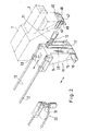
- the drawing shows a headstock 1 one Milling machine that carries a vertical milling head 2 via spacers 3 on its front end.
- the work spindle is mounted in the vertical milling head 2 and is driven in a conventional manner by an electric motor mounted on the headstock 1 via a brake transmission, a dog clutch and at least one bevel gear pair.
- clamping means are provided in the work spindle for releasably gripping and fixing a tool cone.
- a quick coupler 4 is integrated, which contains a pin 6 rotatably and axially displaceably mounted axially parallel to the spindle axis 5 in the milling head 2 and a support member fastened to its lower end in the form of a rectangular plate 7.
- two semicircular cutouts 8, 9 are provided offset from one another by 180 ° on both sides of the bolt 6, the size and shape of which is designed to accommodate a tool cone 10 each.
- spring pliers - not shown - are provided in the area of these cutouts 8, 9, which grip a tool cone and hold it in the support plate 7 during a changing operation.
- the quick coupler 4 is also assigned a rotary drive for controlled rotation by 180 ° and a feed drive for the axial extension and insertion movement of the bolt 6, both of which are integrated in the vertical milling head 2.
- a univer Seller tool changer 11 is provided, which is designed for operating the horizontal spindle and the vertical spindle.
- a support slide 13 is in the direction of the double arrow by means of a - not shown - linear drive, for. B. a spindle drive or a pressure cylinder, guided.
- a vertical support piece 14 is fixedly mounted on the slide 13, in whose lower end part a pivot pin 15 is mounted, which is rotated by a motor 16.
- a pivot lever 17 is wedged onto the free end section of the pivot pin 15, in the free end part of which a pivot pin 18 is mounted in a transverse bore.
- the tool changer 11 is in a retracted position in which its movable parts cannot interfere with the various machining operations.
- the quick coupler 4 is also retracted, so that the support plate 7 in the position shown in solid lines lies approximately on the lower end face of the vertical milling head 2.
- the linear motor for the quick coupler 4 is then actuated by the program control of the milling machine, which moves the bolt 6 and the support member 7 into the position shown in broken lines.
- the collet Since the collet has previously released the tool cone in the work spindle, it is taken away by the support member 7 and its spring elements.
- the quick coupler 4 is then rotated about the axis of the bolt 6, so that the tool cone held in the cutout 8 reaches a position to the side of the vertical milling head 2.
- the part of the support member 7 having the cutout 9 comes into the axial position of the work spindle.
- a new tool cone previously introduced into this cutout 9 is thus in the spindle axis and is inserted into the work spindle by a pulling-in movement caused by the linear drive of the quick coupler 4 and then fixed by actuating its collet.
- the tool located in the cutout 9 on the side next to the vertical milling head 2 is gripped by a pivoting movement of the swivel arm 20 caused by the motor 18 by its - empty - tool holder 21 and is pulled out of the cutout 9 of the support element 7 when it swings back.
- the carriage 13 moves back so far that the removed tool is transferred into a receptacle predetermined by the program in the chain magazine.
- a further tool is removed from the chain magazine 22 by means of the holder 21 and brought into a ready position, from which it can be removed within a very short time, e.g. B. still during the machining process or during the shutdown of the work spindle to which - then empty - cutout 8 of the support element 7 can be transferred. This completes a tool change that is repeated as often as required.
- a quick coupler 40 of the same construction which is built directly into the headstock 1 is assigned.
- This quick coupler 40 contains an axially parallel to the spindle axis of the horizontal spindle in the headstock 1 pivot pin 46, which - with the help of - not shown - drive motors can perform rotary movements by 180 ° and axial movements.
- a plate-shaped support element 47 is fastened, which contains two axially symmetrically arranged tool holders 48, 49 in the form of semicircular cutouts and spring elements.
- the pivot lever 17 is in the position shown in FIG. 2 by the motor 16 pivoted so that the swivel arm 20 can move the tool 10 into the receptacle 49 or remove it from it by moving about the axis of the bolt 19.
Landscapes
- Engineering & Computer Science (AREA)
- Mechanical Engineering (AREA)
- Automatic Tool Replacement In Machine Tools (AREA)
Applications Claiming Priority (2)
| Application Number | Priority Date | Filing Date | Title |
|---|---|---|---|
| DE19863614807 DE3614807A1 (de) | 1986-05-02 | 1986-05-02 | Werkzeugwechsel-vorrichtung |
| DE3614807 | 1986-05-02 |
Publications (2)
| Publication Number | Publication Date |
|---|---|
| EP0243711A2 true EP0243711A2 (fr) | 1987-11-04 |
| EP0243711A3 EP0243711A3 (fr) | 1989-12-27 |
Family
ID=6299975
Family Applications (1)
| Application Number | Title | Priority Date | Filing Date |
|---|---|---|---|
| EP87104822A Withdrawn EP0243711A3 (fr) | 1986-05-02 | 1987-04-01 | Dispositif de changement d'outils |
Country Status (3)
| Country | Link |
|---|---|
| EP (1) | EP0243711A3 (fr) |
| JP (1) | JPS62292336A (fr) |
| DE (1) | DE3614807A1 (fr) |
Cited By (1)
| Publication number | Priority date | Publication date | Assignee | Title |
|---|---|---|---|---|
| EP2460622A3 (fr) * | 2010-12-05 | 2013-06-12 | T + S-Jakob GmbH & Co. KG | Dispositif de changement d'outil automatique |
Families Citing this family (2)
| Publication number | Priority date | Publication date | Assignee | Title |
|---|---|---|---|---|
| DE3918901A1 (de) * | 1989-06-09 | 1990-12-13 | Heller Geb Gmbh Maschf | Wechseleinrichtung fuer werkzeugspindeltraeger an einer bearbeitungsmaschine |
| DE4406386A1 (de) * | 1994-02-26 | 1995-08-31 | Stroemungsmaschinen Gmbh | Einrichtung zum Transport eines Werkzeuges |
Family Cites Families (7)
| Publication number | Priority date | Publication date | Assignee | Title |
|---|---|---|---|---|
| IT1037252B (it) * | 1975-04-14 | 1979-11-10 | Mandelli Spa | Macchina utensile conportante un unico mandrino atto ad assumere automaticamente siala posizione orizzontale quella verticale ed un unico dispositivo di cambio automatico degli utnesili |
| EP0011882B1 (fr) * | 1978-11-29 | 1982-04-07 | Werkzeugmaschinenfabrik Oerlikon-Bührle AG | Machine-outil avec dispositif de changement d'outil |
| JPS5935739B2 (ja) * | 1982-05-14 | 1984-08-30 | 株式会社オ−エム製作所 | 工作機械の工具交換装置 |
| JPS58223543A (ja) * | 1982-06-18 | 1983-12-26 | Hitachi Seiki Co Ltd | 自動工具交換装置 |
| JPS5934935U (ja) * | 1982-08-30 | 1984-03-05 | 株式会社大隈鐵工所 | アタツチメントの自動工具交換装置 |
| DE3344084A1 (de) * | 1983-12-06 | 1985-06-20 | Maho Werkzeugmaschinenbau Babel & Co, 8962 Pfronten | Werkzeugwechsler fuer fraes- und bohrmaschinen |
| JPS60135154A (ja) * | 1983-12-22 | 1985-07-18 | Miyano Tekkosho:Kk | 工作機械における工具交換装置 |
-
1986
- 1986-05-02 DE DE19863614807 patent/DE3614807A1/de active Granted
-
1987
- 1987-04-01 EP EP87104822A patent/EP0243711A3/fr not_active Withdrawn
- 1987-05-01 JP JP10652887A patent/JPS62292336A/ja active Pending
Cited By (1)
| Publication number | Priority date | Publication date | Assignee | Title |
|---|---|---|---|---|
| EP2460622A3 (fr) * | 2010-12-05 | 2013-06-12 | T + S-Jakob GmbH & Co. KG | Dispositif de changement d'outil automatique |
Also Published As
| Publication number | Publication date |
|---|---|
| EP0243711A3 (fr) | 1989-12-27 |
| DE3614807A1 (de) | 1987-11-05 |
| JPS62292336A (ja) | 1987-12-19 |
| DE3614807C2 (fr) | 1989-05-24 |
Similar Documents
| Publication | Publication Date | Title |
|---|---|---|
| EP0216261B1 (fr) | Machine-outil | |
| DE69602079T2 (de) | Werkzeugmaschine mit horizontalen spindeln | |
| DE3035451C2 (fr) | ||
| DE3220026C2 (fr) | ||
| DE3502328C2 (fr) | ||
| DE19860492B4 (de) | Programmgesteuerte Fräs- und Bohrmaschine | |
| EP0368996B1 (fr) | Machine a aleser et a fraiser | |
| DE3322444A1 (de) | Vorrichtung zum wechseln von werkzeugen | |
| EP0307691A1 (fr) | Changeur d'outil pour fraiseuse-aléseuse universelle | |
| DE1602798A1 (de) | Bohr- und Fraeswerk | |
| EP0111046A2 (fr) | Dispositif de changement d'outil pour une machine-outil à broches multiples | |
| DE3872604T2 (de) | Werkzeugmaschine zum drehen, fraesen, bohren und waschen mit unabhaengiger einspannvorrichtung fuer das zu bearbeitende werkstueck. | |
| EP0260692B1 (fr) | Machine-outil avec un porte-broche à forer et à fraiser à déplacement dans la direction Z sur un châssis de machine | |
| DE69102511T2 (de) | Werkzeugmaschine, insbesondere für dekolletieren. | |
| DE10025614A1 (de) | Vorrichtung zum Greifen und Transportieren von Werkstücken in Drehmaschinen | |
| EP1736264B1 (fr) | Dispositif pour l'usinage intérieur de pièces, en particulier de carters d'engrenages différentiels | |
| DE3634018C2 (fr) | ||
| DE112006003145B4 (de) | Zuführungsvorrichtung für ein Schneidwerkzeug zur Innenbearbeitung | |
| EP0941790A1 (fr) | Tour | |
| EP0949029B1 (fr) | Machine outil pour l'usinage des barres | |
| EP0637277B1 (fr) | Dispositif pour l'usinage de metaux par enlevement de copeaux | |
| DE3614807C2 (fr) | ||
| EP1752241B1 (fr) | Tour d'usinage | |
| EP0137117B1 (fr) | Dispositif changeur d'outils comprenant un appareil pour le transfert des têtes d'outils | |
| DE2950934C2 (de) | Flexibles Fertigungssystem mit einer zentralen, eine vertikale Schaltachse und eine horizontale Werkzeug-Antriebsachse aufweisenden Revolverkopf-Bearbeitungseinheit |
Legal Events
| Date | Code | Title | Description |
|---|---|---|---|
| PUAI | Public reference made under article 153(3) epc to a published international application that has entered the european phase |
Free format text: ORIGINAL CODE: 0009012 |
|
| AK | Designated contracting states |
Kind code of ref document: A2 Designated state(s): CH DE FR GB IT LI |
|
| PUAL | Search report despatched |
Free format text: ORIGINAL CODE: 0009013 |
|
| AK | Designated contracting states |
Kind code of ref document: A3 Designated state(s): CH DE FR GB IT LI |
|
| STAA | Information on the status of an ep patent application or granted ep patent |
Free format text: STATUS: THE APPLICATION IS DEEMED TO BE WITHDRAWN |
|
| 18D | Application deemed to be withdrawn |
Effective date: 19900628 |
|
| RIN1 | Information on inventor provided before grant (corrected) |
Inventor name: BABEL, WERNER |