EP0243732B1 - Contre-couteaux pour dispositif à granuler - Google Patents
Contre-couteaux pour dispositif à granuler Download PDFInfo
- Publication number
- EP0243732B1 EP0243732B1 EP87104990A EP87104990A EP0243732B1 EP 0243732 B1 EP0243732 B1 EP 0243732B1 EP 87104990 A EP87104990 A EP 87104990A EP 87104990 A EP87104990 A EP 87104990A EP 0243732 B1 EP0243732 B1 EP 0243732B1
- Authority
- EP
- European Patent Office
- Prior art keywords
- sections
- rod
- counter
- section
- cutting
- Prior art date
- Legal status (The legal status is an assumption and is not a legal conclusion. Google has not performed a legal analysis and makes no representation as to the accuracy of the status listed.)
- Expired - Lifetime
Links
Images

Classifications
-
- B—PERFORMING OPERATIONS; TRANSPORTING
- B26—HAND CUTTING TOOLS; CUTTING; SEVERING
- B26D—CUTTING; DETAILS COMMON TO MACHINES FOR PERFORATING, PUNCHING, CUTTING-OUT, STAMPING-OUT OR SEVERING
- B26D7/00—Details of apparatus for cutting, cutting-out, stamping-out, punching, perforating, or severing by means other than cutting
- B26D7/26—Means for mounting or adjusting the cutting member; Means for adjusting the stroke of the cutting member
- B26D7/2628—Means for adjusting the position of the cutting member
-
- B—PERFORMING OPERATIONS; TRANSPORTING
- B01—PHYSICAL OR CHEMICAL PROCESSES OR APPARATUS IN GENERAL
- B01J—CHEMICAL OR PHYSICAL PROCESSES, e.g. CATALYSIS OR COLLOID CHEMISTRY; THEIR RELEVANT APPARATUS
- B01J2/00—Processes or devices for granulating materials, e.g. fertilisers in general; Rendering particulate materials free flowing in general, e.g. making them hydrophobic
- B01J2/22—Processes or devices for granulating materials, e.g. fertilisers in general; Rendering particulate materials free flowing in general, e.g. making them hydrophobic by pressing in moulds or between rollers
-
- B—PERFORMING OPERATIONS; TRANSPORTING
- B02—CRUSHING, PULVERISING, OR DISINTEGRATING; PREPARATORY TREATMENT OF GRAIN FOR MILLING
- B02C—CRUSHING, PULVERISING, OR DISINTEGRATING IN GENERAL; MILLING GRAIN
- B02C18/00—Disintegrating by knives or other cutting or tearing members which chop material into fragments
- B02C18/06—Disintegrating by knives or other cutting or tearing members which chop material into fragments with rotating knives
- B02C18/14—Disintegrating by knives or other cutting or tearing members which chop material into fragments with rotating knives within horizontal containers
- B02C18/148—Disintegrating by knives or other cutting or tearing members which chop material into fragments with rotating knives within horizontal containers specially adapted for disintegrating plastics, e.g. cinematographic films
-
- B—PERFORMING OPERATIONS; TRANSPORTING
- B02—CRUSHING, PULVERISING, OR DISINTEGRATING; PREPARATORY TREATMENT OF GRAIN FOR MILLING
- B02C—CRUSHING, PULVERISING, OR DISINTEGRATING IN GENERAL; MILLING GRAIN
- B02C18/00—Disintegrating by knives or other cutting or tearing members which chop material into fragments
- B02C18/06—Disintegrating by knives or other cutting or tearing members which chop material into fragments with rotating knives
- B02C18/16—Details
- B02C18/18—Knives; Mountings thereof
- B02C18/186—Axially elongated knives
-
- B—PERFORMING OPERATIONS; TRANSPORTING
- B29—WORKING OF PLASTICS; WORKING OF SUBSTANCES IN A PLASTIC STATE IN GENERAL
- B29B—PREPARATION OR PRETREATMENT OF THE MATERIAL TO BE SHAPED; MAKING GRANULES OR PREFORMS; RECOVERY OF PLASTICS OR OTHER CONSTITUENTS OF WASTE MATERIAL CONTAINING PLASTICS
- B29B9/00—Making granules
- B29B9/02—Making granules by dividing preformed material
- B29B9/06—Making granules by dividing preformed material in the form of filamentary material, e.g. combined with extrusion
-
- B—PERFORMING OPERATIONS; TRANSPORTING
- B02—CRUSHING, PULVERISING, OR DISINTEGRATING; PREPARATORY TREATMENT OF GRAIN FOR MILLING
- B02C—CRUSHING, PULVERISING, OR DISINTEGRATING IN GENERAL; MILLING GRAIN
- B02C18/00—Disintegrating by knives or other cutting or tearing members which chop material into fragments
- B02C18/06—Disintegrating by knives or other cutting or tearing members which chop material into fragments with rotating knives
- B02C18/16—Details
- B02C18/18—Knives; Mountings thereof
- B02C2018/188—Stationary counter-knives; Mountings thereof
-
- Y—GENERAL TAGGING OF NEW TECHNOLOGICAL DEVELOPMENTS; GENERAL TAGGING OF CROSS-SECTIONAL TECHNOLOGIES SPANNING OVER SEVERAL SECTIONS OF THE IPC; TECHNICAL SUBJECTS COVERED BY FORMER USPC CROSS-REFERENCE ART COLLECTIONS [XRACs] AND DIGESTS
- Y10—TECHNICAL SUBJECTS COVERED BY FORMER USPC
- Y10S—TECHNICAL SUBJECTS COVERED BY FORMER USPC CROSS-REFERENCE ART COLLECTIONS [XRACs] AND DIGESTS
- Y10S83/00—Cutting
- Y10S83/906—Chip making
-
- Y—GENERAL TAGGING OF NEW TECHNOLOGICAL DEVELOPMENTS; GENERAL TAGGING OF CROSS-SECTIONAL TECHNOLOGIES SPANNING OVER SEVERAL SECTIONS OF THE IPC; TECHNICAL SUBJECTS COVERED BY FORMER USPC CROSS-REFERENCE ART COLLECTIONS [XRACs] AND DIGESTS
- Y10—TECHNICAL SUBJECTS COVERED BY FORMER USPC
- Y10T—TECHNICAL SUBJECTS COVERED BY FORMER US CLASSIFICATION
- Y10T83/00—Cutting
- Y10T83/465—Cutting motion of tool has component in direction of moving work
- Y10T83/4766—Orbital motion of cutting blade
- Y10T83/4795—Rotary tool
- Y10T83/4847—With cooperating stationary tool
-
- Y—GENERAL TAGGING OF NEW TECHNOLOGICAL DEVELOPMENTS; GENERAL TAGGING OF CROSS-SECTIONAL TECHNOLOGIES SPANNING OVER SEVERAL SECTIONS OF THE IPC; TECHNICAL SUBJECTS COVERED BY FORMER USPC CROSS-REFERENCE ART COLLECTIONS [XRACs] AND DIGESTS
- Y10—TECHNICAL SUBJECTS COVERED BY FORMER USPC
- Y10T—TECHNICAL SUBJECTS COVERED BY FORMER US CLASSIFICATION
- Y10T83/00—Cutting
- Y10T83/485—Cutter with timed stroke relative to moving work
- Y10T83/494—Uniform periodic tool actuation
- Y10T83/501—With plural tools on a single tool support
-
- Y—GENERAL TAGGING OF NEW TECHNOLOGICAL DEVELOPMENTS; GENERAL TAGGING OF CROSS-SECTIONAL TECHNOLOGIES SPANNING OVER SEVERAL SECTIONS OF THE IPC; TECHNICAL SUBJECTS COVERED BY FORMER USPC CROSS-REFERENCE ART COLLECTIONS [XRACs] AND DIGESTS
- Y10—TECHNICAL SUBJECTS COVERED BY FORMER USPC
- Y10T—TECHNICAL SUBJECTS COVERED BY FORMER US CLASSIFICATION
- Y10T83/00—Cutting
- Y10T83/929—Tool or tool with support
- Y10T83/9309—Anvil
-
- Y—GENERAL TAGGING OF NEW TECHNOLOGICAL DEVELOPMENTS; GENERAL TAGGING OF CROSS-SECTIONAL TECHNOLOGIES SPANNING OVER SEVERAL SECTIONS OF THE IPC; TECHNICAL SUBJECTS COVERED BY FORMER USPC CROSS-REFERENCE ART COLLECTIONS [XRACs] AND DIGESTS
- Y10—TECHNICAL SUBJECTS COVERED BY FORMER USPC
- Y10T—TECHNICAL SUBJECTS COVERED BY FORMER US CLASSIFICATION
- Y10T83/00—Cutting
- Y10T83/929—Tool or tool with support
- Y10T83/9457—Joint or connection
- Y10T83/9488—Adjustable
- Y10T83/949—Rectilinearly
Definitions
- the knife bar can be given a precise support in that the wings of the sections form a smoothed flat surface with the surface of the rod in the area of the constriction. Due to this processing, you get a plane, continuous wing that extends over all sections and extends in the relevant part of the surface of the rod.
- This has the advantage that when the screws penetrating the rod are tightened, the rod with the part of its surface which belongs to the supporting surface is pulled against the supporting surface of the supporting beam, with the result that the ceramic cutting material is relieved of excessive pressure.
- sufficient tension is transferred to the part of each section consisting of the ceramic cutting material, since due to the elasticity of the rod material, in particular steel, a certain deformation of the rod occurs which is greater than that of the ceramic cutting material.
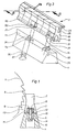
- the sections 18 contain as a recess the circular bore 19 which extends in alignment over all sections 18.
- the holes 19 and 26 are shown empty.
- the bore 19 then contains the rod 20 and the bore 26 the axis 25 in the assembled state.
- the elongated hole 31 or 32 according to FIG. 3 is drawn in the sectional view according to FIG. 4, which represents a section along the line C-C from FIG. 2. 4 protrudes into the elongated hole 31/32, the screw 6, which can be guided back and forth in the longitudinal direction of the elongated hole 31/32 practically without play.
Landscapes
- Engineering & Computer Science (AREA)
- Chemical & Material Sciences (AREA)
- Food Science & Technology (AREA)
- Mechanical Engineering (AREA)
- Organic Chemistry (AREA)
- Chemical Kinetics & Catalysis (AREA)
- Life Sciences & Earth Sciences (AREA)
- Forests & Forestry (AREA)
- Processing And Handling Of Plastics And Other Materials For Molding In General (AREA)
- Crushing And Pulverization Processes (AREA)
- Knives (AREA)
Claims (9)
- Barre de contre-lame (3), destinée à coopérer avec une lame de coupe (1) déplacée devant elle, notamment pour la granulation de boudins (24) de matière plastique, et constituée de tronçons individuels identiques juxtaposés (2 ; 18), chaque tronçon étant configuré de telle sorte qu'il s'étend sur la région d'alimentation et d'évacuation du matériau à couper ou coupé, et lesdits tronçons étant fixés sur une poutre porteuse (4) et formant un tranchant continu en matériau coupant résistant à l'usure, caractérisée en ce que chaque tronçon (2 ; 18) est réalisé sensiblement totalement en matériau coupant céramique et est doté d'un évidement (9 ; 19), qui s'étend dans la direction de la barre de contre-lame (3) et qui, en partant d'une face extérieure (10) du tronçon (2 ; 18), est réalisé sous la forme d'une partie rétrécie (13 ; 22) suivie d'une partie élargie s'étendant à l'intérieur du tronçon (2 ; 18), les évidements (9 ; 19) de tous les tronçons (2 ; 18) étant mutuellement alignés et recevant un barreau continu (7 ; 20) de mêmes dimensions, qui s'étend sur plusieurs tronçons (2 ; 18) et peut être serré contre la poutre porteuse (4), conjointement avec les tronçons (2 ; 18), au moyen de vis (6) qui traversent la partie rétrécie (13 ; 22), pénètrent dans des trous filetés (8 ; 21) du barreau (7 ; 20) et s'appuient contre la poutre porteuse (4), un axe (25), s'étendant parallèlement audit barreau et traversant les tronçons (2 ; 18), étant associé audit barreau comme sécurité supplémentaire pour empêcher la rotation des tronçons (2 ; 18) les uns par rapport aux autres.
- Barre de contre-lame selon la revendication 1, caractérisée en ce que l'évidement (9 ; 19) part de la face extérieure des tronçons (2 ; 18) qui, lors de la coupe, s'appuie comme face porteuse plane (10) contre une face d'appui (11) de la poutre porteuse (4).
- Barre de contre-lame selon la revendication 2, caractérisée en ce que l'évidement (9) se raccorde à la partie rétrécie (13) par un gradin d'appui (12) qui s'étend parallèlement à la face porteuse (10).
- Barre de contre-lame selon la revendication 1 ou 2, caractérisée en ce que l'évidement est réalisé sous la forme d'un perçage circulaire (19), doté d'une ouverture latérale en forme de segment de cercle qui constitue la partie rétrécie (22).
- Barre de contre-lame selon l'une quelconque des revendications précédentes, caractérisée en ce qu'on a prévu, comme sécurité supplémentaire pour empêcher la rotation des tronçons (18) les uns par rapport aux autres, un axe (25) qui traverse les tronçons (18) parallèlement au barreau (20).
- Barre de contre-lame selon l'une quelconque des revendications précédentes, caractérisée en ce que les tronçons (18) sont assemblés par collage au barreau (20) et a l'axe (25).
- Barre de contre-lame selon l'une quelconque des revendications précédentes, caractérisée en ce que les tronçons sont assemblés au barreau (20) et à l'axe (25) en étant serrés par un assemblage vissé aux extrémités de ces derniers.
- Barre de contre-lame selon l'une quelconque des revendications 2 à 7, caractérisée en ce que les faces porteuses (10) des tronçons (2 ; 18) forment une surface rectifiée plane avec la surface du barreau (7 ; 20) dans la région de la partie rétrécie (13 ; 22).
- Barre de contre-lame selon l'une quelconque des revendications 5 à 7, caractérisée en ce que les vis (6) traversent sensiblement sans jeu des trous oblongs (14), pratiqués dans la poutre porteuse (4) et s'étendant perpendiculairement au barreau (7 ; 20), et en ce que le barreau (7 ; 20) est pourvu de fentes (31 ; 32), qui s'étendent dans sa direction longitudinale et dans lesquelles s'adaptent des pointes (33 ; 34) dépassant excentriquement d'un pivot (35 ; 36) monté dans la poutre porteuse (4), ces pointes permettant, en faisant tourner le pivot (35 ; 36), de décaler le barreau (7 ; 20) et donc les tronçons (2 ; 18) dans la direction des trous oblongs (14).
Applications Claiming Priority (2)
| Application Number | Priority Date | Filing Date | Title |
|---|---|---|---|
| DE3611179A DE3611179C1 (de) | 1986-04-03 | 1986-04-03 | Messerleiste,insbesondere zum Granulieren von Kunststoffstraengen |
| DE3611179 | 1986-04-03 |
Publications (3)
| Publication Number | Publication Date |
|---|---|
| EP0243732A2 EP0243732A2 (fr) | 1987-11-04 |
| EP0243732A3 EP0243732A3 (en) | 1990-01-31 |
| EP0243732B1 true EP0243732B1 (fr) | 1993-09-15 |
Family
ID=6297834
Family Applications (1)
| Application Number | Title | Priority Date | Filing Date |
|---|---|---|---|
| EP87104990A Expired - Lifetime EP0243732B1 (fr) | 1986-04-03 | 1987-04-03 | Contre-couteaux pour dispositif à granuler |
Country Status (4)
| Country | Link |
|---|---|
| US (1) | US4759248A (fr) |
| EP (1) | EP0243732B1 (fr) |
| DE (1) | DE3611179C1 (fr) |
| ES (1) | ES2043615T3 (fr) |
Families Citing this family (19)
| Publication number | Priority date | Publication date | Assignee | Title |
|---|---|---|---|---|
| US5020404A (en) * | 1989-06-30 | 1991-06-04 | Hoeh James A | Testing apparatus for strand pelletizing operation |
| JPH0613175B2 (ja) * | 1989-07-31 | 1994-02-23 | 株式会社クラレ | ペレツトの製造法 |
| US5265507A (en) * | 1989-07-31 | 1993-11-30 | Kuraray Co., Ltd. | Process for producing pellets |
| DE4236451C1 (de) * | 1992-10-28 | 1993-11-04 | Scheer & Cie C F | Granuliervorrichtung fuer strangmaterialien |
| US5711492A (en) * | 1994-07-08 | 1998-01-27 | T.P.L. Products, Inc. | Composite machine elements from fiber reinforced polymers and advanced wear ceramics |
| JPH09314555A (ja) * | 1996-05-30 | 1997-12-09 | Kako Kiki Kk | 熱可塑性樹脂造粒機用カッターナイフ及びその製造方法 |
| US6269714B1 (en) * | 1996-05-30 | 2001-08-07 | Kakoh Kiki Co., Ltd. | Cutter knife for thermoplastic resin pelletizer and production method of said cutter knife |
| DE10005950B4 (de) * | 2000-02-09 | 2004-11-25 | Joachim Kozlowski | Schienenförmiges Untermesser |
| DE10103827B4 (de) * | 2001-01-29 | 2005-12-29 | Rieter Automatik Gmbh | Messeranordnung für einen Granulator zum Granulieren von Kunststoffsträngen |
| CN1206084C (zh) * | 2002-05-28 | 2005-06-15 | 肖友谊 | 粘结式陶瓷切粒刀 |
| DE102007044201A1 (de) | 2007-09-17 | 2009-03-19 | Rieter Automatik Gmbh | Vorrichtung zum Granulieren von Kunststoffsträngen |
| DE202007014782U1 (de) * | 2007-10-23 | 2009-03-05 | Rieter Automatik Gmbh | Stranggranulierungsvorrichtung |
| EP2459453A1 (fr) * | 2009-07-29 | 2012-06-06 | Sidel S.p.A. | Unité de coupe pour machines d'étiquetage avec un tambour rotatif à lames multiples |
| WO2011012926A1 (fr) * | 2009-07-29 | 2011-02-03 | Sidel S.P.A. | Unité de coupe pour machines d'étiquetage |
| EP2529836A1 (fr) * | 2011-05-30 | 2012-12-05 | LANXESS Deutschland GmbH | Procédé de broyage d'un élastomère et broyeur |
| DE102014108607A1 (de) * | 2014-06-18 | 2015-12-24 | Betek Gmbh & Co. Kg | Gegenschneide |
| EP3689571B1 (fr) * | 2019-01-29 | 2023-04-05 | Coperion GmbH | Granulateur à joncs, et procédé de réglage du jeu de coupe d'un tel granulateur |
| CN117651637A (zh) * | 2021-08-09 | 2024-03-05 | 埃克森美孚化学专利公司 | 利用聚晶金刚石元件的聚合物挤出装置和方法 |
| CN116690657B (zh) * | 2022-02-25 | 2025-11-18 | 宁德时代新能源科技股份有限公司 | 裁切装置、裁切方法以及电池制造设备 |
Family Cites Families (9)
| Publication number | Priority date | Publication date | Assignee | Title |
|---|---|---|---|---|
| CA532643A (fr) * | 1956-11-06 | John W. Bolton And Sons | Coupoirs | |
| US2193148A (en) * | 1938-03-30 | 1940-03-12 | George P Thomas | Shear |
| US2857111A (en) * | 1955-01-21 | 1958-10-21 | Unipulver Ltd | Rotor blades and blade mounting means for grinding mills |
| GB922341A (en) * | 1958-06-13 | 1963-03-27 | Munters Carl Georg | Improvements in or relating to the production of saw tooth serrations in sheets of material such as paper |
| DE2259315A1 (de) * | 1972-12-04 | 1974-06-06 | Henry Neuenburg | Fraeswalze fuer strassenfraesen oder dergleichen |
| US3822625A (en) * | 1973-02-09 | 1974-07-09 | Westvaco Corp | Rotary cutter with quick change knife |
| US4204451A (en) * | 1977-12-19 | 1980-05-27 | Reichert Leonard K | Cutting block employing cuttable rods |
| US4219291A (en) * | 1979-03-14 | 1980-08-26 | Hoeh James A | Segmented helical rotary cutter and method of making same |
| DE3108954C2 (de) * | 1981-03-10 | 1986-07-24 | Michael Dr.-Ing. 3100 Celle Kaiser | Messer und Verfahren zu seiner Herstellung |
-
1986
- 1986-04-03 DE DE3611179A patent/DE3611179C1/de not_active Expired
-
1987
- 1987-04-02 US US07/034,074 patent/US4759248A/en not_active Expired - Fee Related
- 1987-04-03 ES ES87104990T patent/ES2043615T3/es not_active Expired - Lifetime
- 1987-04-03 EP EP87104990A patent/EP0243732B1/fr not_active Expired - Lifetime
Also Published As
| Publication number | Publication date |
|---|---|
| EP0243732A2 (fr) | 1987-11-04 |
| EP0243732A3 (en) | 1990-01-31 |
| DE3611179C1 (de) | 1987-11-26 |
| US4759248A (en) | 1988-07-26 |
| ES2043615T3 (es) | 1994-01-01 |
Similar Documents
| Publication | Publication Date | Title |
|---|---|---|
| EP0243732B1 (fr) | Contre-couteaux pour dispositif à granuler | |
| DE4344801C2 (de) | Granulator | |
| EP1768771B1 (fr) | Dispositif de melange | |
| EP0377060B1 (fr) | Outil de coupe rotatif, en particulier pour la granulation de rubans de matière synthétique | |
| DE2848976A1 (de) | Vorrichtung zum maschinellen behandeln der oberflaeche von langhoelzern | |
| EP2598247B1 (fr) | Aube directrice pour un dispositif de broyage | |
| DE10026825C2 (de) | Zerkleinerungsvorrichtung | |
| DE19703495C2 (de) | Trogmischer | |
| DE3216092C2 (de) | Zerkleinerer für Material aus Kunststoff | |
| DE4319058A1 (de) | Schneckenwelle | |
| DE69221518T2 (de) | Webschaft für einen Webstuhl | |
| AT407847B (de) | Halterung für messer von granuliervorrichtungen | |
| DE69607030T2 (de) | Messern für die schraubenwinde von misch- und schneidemaschinen | |
| DE2065612C3 (de) | Befestigung für ein im Querschnitt ein Parallelogramm bildendes Messer an einer Messertrommel | |
| DE3242999C1 (de) | Schneckenpresse zum mechanischen Trennen von Fluessigkeitsfeststoffgemischen | |
| DE3806159A1 (de) | Walzenmuehle | |
| DE3304206A1 (de) | Schneidwerkzeug und halter | |
| DE3613071C2 (fr) | ||
| EP0887164A1 (fr) | Matrice de formage pour extrudeuse | |
| DE4429792C2 (de) | Verfahren und Kollergang zum Zerkleinern von mineralischen Rohstoffen | |
| EP0095515B1 (fr) | Dispositif de dosage pour des flocs | |
| EP3980195B1 (fr) | Rouleau de saupoudrage pour un dispositif de distribution | |
| DE2145364A1 (de) | Spritzkopf fuer eine kunststoff-spritzmaschine | |
| DE3517234C1 (de) | Gegenmesser-Schnellspannvorrichtung | |
| DE3645293C2 (de) | Auflöseeinrichtung an einer Mischeinrichtung für einem Mahlwerkzeug zuzuführendes körniges Gut |
Legal Events
| Date | Code | Title | Description |
|---|---|---|---|
| PUAI | Public reference made under article 153(3) epc to a published international application that has entered the european phase |
Free format text: ORIGINAL CODE: 0009012 |
|
| AK | Designated contracting states |
Kind code of ref document: A2 Designated state(s): BE CH ES FR IT LI NL |
|
| PUAL | Search report despatched |
Free format text: ORIGINAL CODE: 0009013 |
|
| AK | Designated contracting states |
Kind code of ref document: A3 Designated state(s): BE CH ES FR IT LI NL |
|
| 17P | Request for examination filed |
Effective date: 19900712 |
|
| 17Q | First examination report despatched |
Effective date: 19911204 |
|
| RAP1 | Party data changed (applicant data changed or rights of an application transferred) |
Owner name: RIETER AUTOMATIK GMBH |
|
| GRAA | (expected) grant |
Free format text: ORIGINAL CODE: 0009210 |
|
| AK | Designated contracting states |
Kind code of ref document: B1 Designated state(s): BE CH ES FR IT LI NL |
|
| ITF | It: translation for a ep patent filed | ||
| ET | Fr: translation filed | ||
| REG | Reference to a national code |
Ref country code: ES Ref legal event code: FG2A Ref document number: 2043615 Country of ref document: ES Kind code of ref document: T3 |
|
| PLBE | No opposition filed within time limit |
Free format text: ORIGINAL CODE: 0009261 |
|
| STAA | Information on the status of an ep patent application or granted ep patent |
Free format text: STATUS: NO OPPOSITION FILED WITHIN TIME LIMIT |
|
| 26N | No opposition filed | ||
| PGFP | Annual fee paid to national office [announced via postgrant information from national office to epo] |
Ref country code: FR Payment date: 19950413 Year of fee payment: 9 |
|
| PGFP | Annual fee paid to national office [announced via postgrant information from national office to epo] |
Ref country code: ES Payment date: 19950428 Year of fee payment: 9 |
|
| PGFP | Annual fee paid to national office [announced via postgrant information from national office to epo] |
Ref country code: NL Payment date: 19950430 Year of fee payment: 9 |
|
| PGFP | Annual fee paid to national office [announced via postgrant information from national office to epo] |
Ref country code: BE Payment date: 19950510 Year of fee payment: 9 |
|
| PGFP | Annual fee paid to national office [announced via postgrant information from national office to epo] |
Ref country code: CH Payment date: 19950519 Year of fee payment: 9 |
|
| PG25 | Lapsed in a contracting state [announced via postgrant information from national office to epo] |
Ref country code: ES Free format text: LAPSE BECAUSE OF NON-PAYMENT OF DUE FEES Effective date: 19960406 |
|
| PG25 | Lapsed in a contracting state [announced via postgrant information from national office to epo] |
Ref country code: LI Effective date: 19960430 Ref country code: CH Effective date: 19960430 Ref country code: BE Effective date: 19960430 |
|
| BERE | Be: lapsed |
Owner name: RIETER AUTOMATIK G.M.B.H. Effective date: 19960430 |
|
| PG25 | Lapsed in a contracting state [announced via postgrant information from national office to epo] |
Ref country code: NL Effective date: 19961101 |
|
| REG | Reference to a national code |
Ref country code: CH Ref legal event code: PL |
|
| PG25 | Lapsed in a contracting state [announced via postgrant information from national office to epo] |
Ref country code: FR Effective date: 19961227 |
|
| NLV4 | Nl: lapsed or anulled due to non-payment of the annual fee |
Effective date: 19961101 |
|
| REG | Reference to a national code |
Ref country code: FR Ref legal event code: ST |
|
| REG | Reference to a national code |
Ref country code: ES Ref legal event code: FD2A Effective date: 19990201 |
|
| PG25 | Lapsed in a contracting state [announced via postgrant information from national office to epo] |
Ref country code: IT Free format text: LAPSE BECAUSE OF NON-PAYMENT OF DUE FEES Effective date: 20050403 |