EP0243795A2 - Dispositif pour guider des viroles arrondies à travers une zône de soudage - Google Patents
Dispositif pour guider des viroles arrondies à travers une zône de soudage Download PDFInfo
- Publication number
- EP0243795A2 EP0243795A2 EP87105558A EP87105558A EP0243795A2 EP 0243795 A2 EP0243795 A2 EP 0243795A2 EP 87105558 A EP87105558 A EP 87105558A EP 87105558 A EP87105558 A EP 87105558A EP 0243795 A2 EP0243795 A2 EP 0243795A2
- Authority
- EP
- European Patent Office
- Prior art keywords
- frames
- chains
- welding
- guide elements
- chain
- Prior art date
- Legal status (The legal status is an assumption and is not a legal conclusion. Google has not performed a legal analysis and makes no representation as to the accuracy of the status listed.)
- Granted
Links
Images


Classifications
-
- B—PERFORMING OPERATIONS; TRANSPORTING
- B23—MACHINE TOOLS; METAL-WORKING NOT OTHERWISE PROVIDED FOR
- B23K—SOLDERING OR UNSOLDERING; WELDING; CLADDING OR PLATING BY SOLDERING OR WELDING; CUTTING BY APPLYING HEAT LOCALLY, e.g. FLAME CUTTING; WORKING BY LASER BEAM
- B23K37/00—Auxiliary devices or processes, not specially adapted for a procedure covered by only one of the other main groups of this subclass
- B23K37/04—Auxiliary devices or processes, not specially adapted for a procedure covered by only one of the other main groups of this subclass for holding or positioning work
- B23K37/053—Auxiliary devices or processes, not specially adapted for a procedure covered by only one of the other main groups of this subclass for holding or positioning work aligning cylindrical work; Clamping devices therefor
-
- B—PERFORMING OPERATIONS; TRANSPORTING
- B23—MACHINE TOOLS; METAL-WORKING NOT OTHERWISE PROVIDED FOR
- B23K—SOLDERING OR UNSOLDERING; WELDING; CLADDING OR PLATING BY SOLDERING OR WELDING; CUTTING BY APPLYING HEAT LOCALLY, e.g. FLAME CUTTING; WORKING BY LASER BEAM
- B23K26/00—Working by laser beam, e.g. welding, cutting or boring
- B23K26/20—Bonding
- B23K26/21—Bonding by welding
- B23K26/24—Seam welding
- B23K26/244—Overlap seam welding
-
- B—PERFORMING OPERATIONS; TRANSPORTING
- B23—MACHINE TOOLS; METAL-WORKING NOT OTHERWISE PROVIDED FOR
- B23K—SOLDERING OR UNSOLDERING; WELDING; CLADDING OR PLATING BY SOLDERING OR WELDING; CUTTING BY APPLYING HEAT LOCALLY, e.g. FLAME CUTTING; WORKING BY LASER BEAM
- B23K26/00—Working by laser beam, e.g. welding, cutting or boring
- B23K26/20—Bonding
- B23K26/21—Bonding by welding
- B23K26/24—Seam welding
- B23K26/26—Seam welding of rectilinear seams
- B23K26/262—Seam welding of rectilinear seams of longitudinal seams of tubes
-
- B—PERFORMING OPERATIONS; TRANSPORTING
- B23—MACHINE TOOLS; METAL-WORKING NOT OTHERWISE PROVIDED FOR
- B23K—SOLDERING OR UNSOLDERING; WELDING; CLADDING OR PLATING BY SOLDERING OR WELDING; CUTTING BY APPLYING HEAT LOCALLY, e.g. FLAME CUTTING; WORKING BY LASER BEAM
- B23K2101/00—Articles made by soldering, welding or cutting
- B23K2101/04—Tubular or hollow articles
- B23K2101/12—Vessels
- B23K2101/125—Cans
Definitions
- the invention relates to a device for passing rounded frames through a welding zone of a machine for welding the longitudinal edges of the frames, with groups of movable guide elements which are opposite one another with respect to the frames and exert radial executives thereon.
- diabolo-like rollers are arranged as guide elements around the axis along which the frames move. Some of these rollers are supported in a radially resilient manner in such a way that they exert forces on the frames which endeavor to press their longitudinal edges against a stationary guide rail of a Z-shaped profile.
- Such guide elements which can only be moved in the radial direction and can be rotated about their own axes, serve their purpose perfectly if the frames which are passed through the welding zone have a diameter of the order of 50 mm or more, in particular if the longitudinal edges of the frames are in one Overlap squeeze seam to be welded.
- Difficulties can occur with known devices of the type described, however, if the frame diameter is less than 50 mm and / or the longitudinal edges of the frames are butt-welded together, especially by means of a laser beam. In such cases, the quality of the weld seam can be reduced by barely noticeable shocks, which occur when one of the numerous roller-shaped guide elements arranged in or near the welding zone only rolls over the front and later over the rear end of a frame.
- the invention is therefore based on the object of designing a device for passing rounded frames through a welding zone in such a way that it is also suitable for frames of small diameter of, for example, 32 or 25 mm and in particular for laser welding the longitudinal edges of such frames. Frames of such a small diameter are required above all for electrical batteries.
- the object is achieved according to the invention in a device of the type described in the introduction in that the guide elements of each group are arranged on an endless chain which has a chain strand running in the direction of movement of the frames, which on both sides contains a plane containing the welding zone and normal to the direction of movement of the frames, the welding plane, is supported by a rail.
- a transport system for can frames in resistance welding machines is known (DE-OS 28 10 188), in which two chains provided with cam-like carriers are arranged one behind the other, one chain of which passes through a station for rounding frames, in which it rotates during the rounding of the frames Frames are at least approximately stationary at times, while the second chain connects to the first chain and takes over the rounded frames from it in order to move them to the welding zone.
- the second chain ends at a distance from the welding plane; it does not guide the rounded frames, but only pushes them forward until they are gripped by two electrode rollers and conveyed by them.
- calibration tools are provided which are independent of the chains and which, like described above, act on the frames with diabolo-type rollers and do not participate in their conveying movement.
- the guide elements while they exercise the necessary radial managers on the frames, move together with them through the welding plane and are supported on both sides of the welding plane, i.e. upstream and downstream of it, on the associated rail .
- This avoids sudden impacts on the frames in the vicinity of the welding plane; the longitudinal edges of the frames consequently move smoothly and evenly through the welding zone.
- Each of the rails preferably extends continuously and in a straight line between a start and an end, the distance from the welding plane of which is greater than the length of each individual frame.
- the guide elements each have a cylindrical contact surface for the frames.
- the chains are preferably designed as roller chains and are supported by their rollers on the associated rail.
- the frames are conveyed through the welding plane in a known manner, for example by means of reciprocating drivers, or are only conveyed up to the welding plane and then moved on by electrode rollers. In such cases, it is basically possible with essentially friction-free guidance and deflection of the chains that the chains are without their own drive and are simply taken along by the frames.
- the chains each wrap around a drive wheel via which they can be driven.
- This preferred embodiment is expediently developed in that at least one of the chains, together with the associated rail and a chain tensioning wheel, can be pivoted away from the opposite chain around the associated drive wheel. In this way, the device according to the invention for maintenance and for eliminating faults can be easily opened.
- each of the rails is supported radially on two springs which are offset from one another in the conveying direction and are adjustable independently of one another.
- a slide rail leading the longitudinal edges of the frames can be arranged, in particular a rail with a Z-shaped profile, which is usually referred to as a Z-rail. It is advantageous if, according to a further feature of the invention, the slide rail is arranged diametrically opposite a magnetic rail additionally guiding the frames.
- a guide sleeve is arranged upstream of the chains, which tapers in a funnel shape in the direction of movement of the frames and minimizes least has an axial slot, along which a pawl for inserting the frames between the chains is movable.
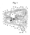
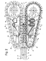
- the device shown has the task of cylindrically rounded frames 10, which consist, for example, of uncoated steel sheet or tinplate, in such a way that their longitudinal edges 12 and 14 can be welded tightly to one another, while the frames 10 along their axis A forward, in Fig. 1 and 2 from left to right, through a normal to the axis A welding plane B.
- Such welded housings are provided in particular as housings for electric batteries.
- the frames 10 were rolled around a stationary lower arm 16 by a round device of conventional design, which extends parallel to the usual horizontal axis A through a likewise stationary guide sleeve 18 and is centered in the illustrated one Device protrudes.
- a round device of conventional design which extends parallel to the usual horizontal axis A through a likewise stationary guide sleeve 18 and is centered in the illustrated one Device protrudes.
- Fixed slide rail 20 of Z-shaped profile, on which the longitudinal edges 14 and 16 of the frames are guided.
- the slide rail 20 ends shortly before the welding plane B, in which a laser cannon 22 is arranged, the beam 24 of which is indicated in FIG. 4.
- the longitudinal edges 12 and 14 run between a front end section 26 of the lower arm 16 and a slide shoe 28 arranged above it, both of which are perforated in such a way that they do not obstruct the beam 24.
- a cooled absorber 30 is arranged vertically below it.
- a pawl 32 is provided which can be moved back and forth parallel to the axis A by means of a conventional drive device, not shown, for example of the type of a crank drive, and each time it moves forward through an axial slot 34 the guide sleeve 18 protrudes into the interior.
- a conventional drive device not shown, for example of the type of a crank drive
- Each frame 10 which emerges from the guide sleeve 18 is gripped by two groups of guide elements 36 which are each arranged on an endless chain 38.
- the two chains 38 are arranged symmetrically with respect to the axis A, each have a chain strand running parallel to it and extend in a horizontal plane around a drive wheel 40 and a chain tensioning wheel 42.
- a chain tensioning wheel 42 Of the chain tensioning wheels 42 from the chains 38 converge towards their axially parallel chain strands.
- both chains 38 are designed as triple roller chains; their members are connected to each other by hinge bolts 44, on which three rollers 46 are mounted.
- Each of the guide elements 36 is fastened to two adjacent hinge pins 44 and has a cylindrical contact surface 48, the diameter of which corresponds to the outer diameter of the frames 10.
- Each of the frames 10 is gripped by three guide elements 36 on both sides of the frame length shown and is guided along the axis A through the welding plane B.
- a driver 50 is attached to the last of the three guide elements 36.
- the drivers 50 on the two axially parallel chain strands face each other in pairs, so that each frame 10 is grasped by a pair of drivers 50, which lies against its rear end, and is therefore reliably moved through the welding plane B when the radial forces are present which the guide elements 36 act on the frames 10 via their contact surfaces 48 should be too weak to generate sufficient frictional forces to take the frames with them.
- the magnitude of the radial forces mentioned is determined in that the straight chain strand of each of the two chains 38 is supported on a rail 52.
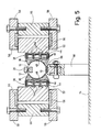
- Each of the rails 52 has three guide ribs 54 arranged one above the other parallel to the axis A, on which the rollers 46 of the associated chain 38 run.
- the length of the guide ribs 54 in front of and behind the welding plane B is greater than the frame length; as a result, each frame 10 is guided via the guide elements 36 accompanying it from a point in time before the front end of the frame reaches the welding plane B to a point in time after its rear end has left the welding plane.
- Each of the two rails 52 is slidably guided between two sliding plates 56, each of which is attached to a cheek 58.
- two threaded bolts 60 are screwed, which extend in a horizontal plane radially to the axis A and are guided in a support 62 which is fastened between the two associated cheeks 58.
- two compression springs 64 are clamped, which are arranged around each of the threaded bolts 60 and the rail with a supporting force of the order of magnitude, for example Support 25 to 30 kg. In this way, the axially parallel chain strand of each of the two chains 38 is adjustably supported by the associated rail 52 in a radial direction with respect to the axis A.
- a further support 66 is fastened to the associated cheeks 58, on which the associated chain tensioning wheel 42 is displaceably guided and is also supported by a compression spring 68.
- the two drive wheels 40 are each attached to a vertical shaft 70, which is mounted in a sleeve 72.
- the two sleeves 72 are fastened to a common, fixed base plate 74.
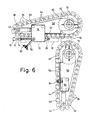
- the two pairs of cheeks 58 belonging together are each mounted on one of the two shafts 70, so that they can be pivoted away from one another into a maintenance position about the associated shaft from their operating position shown in FIGS. 1 to 5.
- a pair of cheeks 58 including associated device parts in particular chain 38 including guide elements 36 and chain tensioning wheel 42, is pivoted into the maintenance position, while the other pair of cheeks 58 including associated device parts are still in their operating position.
- a lock plate 76 is fastened to the upper cheek 58 of one of the two cheek pairs, on which a tie rod 78 is pivotably mounted.
- a lock plate 80 is fastened in a corresponding manner to the upper cheek 58 of the other cheek pair, which can be clamped together with the lock plate 76 in the operating position of the device by means of the tie rod 78 and a screw handle 82 screwed onto it.
- the distance between the axially parallel chain strands of the two chains 38 in the operating position is determined by an adjustable stop screw 84 which is screwed into the lock plate 80 and abuts the lock plate 76 with one of its end faces.
- the two shafts 70 can be driven in opposite directions at exactly the same speed;
- a controllable electric motor 86 is connected via a toothed pinion 88 and a toothed belt 90 to two toothed wheels 92, which are each attached to one of the shafts 70.
- the toothed belt 90 additionally wraps around a deflection wheel 94 which is mounted on the base plate 94.
- the drawings show how four frames 10 pass through the device described in the foregoing at fixed intervals and are guided by the guide elements 36 on the axially parallel chain strands.
- the longitudinal edges 12 and 14 are welded together by the beam 24.
- the welded frames 10 are then conveyed further between the axially parallel chain strands and finally delivered at a relatively large distance from the welding plane B, for example to a further processing device.
- a magnetic rail 96 is fastened on supports 98 below the slide rail 20.
- the frames 10 slide in a region diametrically opposite their longitudinal edges 12 and 14 on the magnetic rail 96 before and while they are gripped by the guide elements 36. This ensures that the frames 10 assume exactly a predetermined position with respect to the guide elements 36.
- the magnet strength is chosen so that the frictional force between each frame 10 and the magnetic rail 96 corresponds at least approximately to the sum of the frictional forces between the longitudinal edges 12 and 14 and the slide rail 20. As a result, the moments of these frictional forces are at least approximately in equilibrium and can therefore not tilt the frame 10.
Landscapes
- Physics & Mathematics (AREA)
- Optics & Photonics (AREA)
- Engineering & Computer Science (AREA)
- Mechanical Engineering (AREA)
- Plasma & Fusion (AREA)
- Advancing Webs (AREA)
- Laser Beam Processing (AREA)
Applications Claiming Priority (2)
| Application Number | Priority Date | Filing Date | Title |
|---|---|---|---|
| CH1628/86 | 1986-04-22 | ||
| CH1628/86A CH669921A5 (fr) | 1986-04-22 | 1986-04-22 |
Publications (3)
| Publication Number | Publication Date |
|---|---|
| EP0243795A2 true EP0243795A2 (fr) | 1987-11-04 |
| EP0243795A3 EP0243795A3 (en) | 1989-01-04 |
| EP0243795B1 EP0243795B1 (fr) | 1990-07-25 |
Family
ID=4214888
Family Applications (1)
| Application Number | Title | Priority Date | Filing Date |
|---|---|---|---|
| EP87105558A Expired - Lifetime EP0243795B1 (fr) | 1986-04-22 | 1987-04-14 | Dispositif pour guider des viroles arrondies à travers une zône de soudage |
Country Status (7)
| Country | Link |
|---|---|
| US (1) | US4741468A (fr) |
| EP (1) | EP0243795B1 (fr) |
| JP (1) | JPS62254937A (fr) |
| CH (1) | CH669921A5 (fr) |
| DE (2) | DE3615706A1 (fr) |
| ES (1) | ES2016820B3 (fr) |
| GR (1) | GR3000954T3 (fr) |
Families Citing this family (18)
| Publication number | Priority date | Publication date | Assignee | Title |
|---|---|---|---|---|
| DE3703270A1 (de) * | 1987-02-04 | 1988-08-18 | Krupp Gmbh | Verfahren zur herstellung eines behaelterrumpfes mit stumpfgeschweisster laengsnaht aus einem blechzuschnitt und vorrichtung zur durchfuehrung des verfahrens |
| CH674169A5 (fr) * | 1987-05-11 | 1990-05-15 | Elpatronic Ag | |
| DE3826953A1 (de) * | 1988-08-09 | 1990-03-01 | Transnorm System Gmbh | Kurvengurtfoerderer |
| JPH0616953B2 (ja) * | 1989-05-16 | 1994-03-09 | 東洋製罐株式会社 | 乾電池用外装缶の製造装置 |
| DE3932551C2 (de) * | 1989-09-29 | 1998-07-09 | Krupp Kunststofftechnik Gmbh | Einrichtung zum Zuführen gerundeter Dosenzargen in den Bereich einer Schweißeinheit |
| DE4024277A1 (de) * | 1990-07-31 | 1992-02-06 | Hetran Maschinen Vertriebs Gmb | Vorrichtung zum bewegen stangenfoermigen gutes in richtung seiner laengsachse |
| DE29718929U1 (de) * | 1997-10-23 | 1998-02-19 | Heuft Systemtechnik Gmbh, 56659 Burgbrohl | Vorrichtung zum Transportieren von Gegenständen zwischen zwei Transportriemen |
| DE19803297A1 (de) * | 1998-01-29 | 1999-08-05 | Rovema Gmbh | Vorrichtung zum Transportieren von stückigem Produkt |
| DE19829433A1 (de) | 1998-07-01 | 2000-01-05 | Kolbus Gmbh & Co Kg | Fördervorrichtung für Buchbindemaschinen |
| JP2003001323A (ja) * | 2001-06-13 | 2003-01-07 | Mitsubishi Shindoh Co Ltd | 電縫管のスクイズロールユニット装置 |
| CN1292873C (zh) * | 2004-05-14 | 2007-01-03 | 武汉楚天激光(集团)股份有限公司 | 激光焊接机的自动送料装置 |
| DE102004039577B3 (de) * | 2004-08-14 | 2006-02-02 | Weil Engineering Gmbh | Vorrichtung zum Herstellen von Rohren |
| US8337750B2 (en) * | 2005-09-13 | 2012-12-25 | Ati Properties, Inc. | Titanium alloys including increased oxygen content and exhibiting improved mechanical properties |
| GB2433908B (en) * | 2006-06-03 | 2008-05-07 | Brecknell Willis & Co Ltd | Conductor rails |
| DE102007018387B4 (de) * | 2007-04-17 | 2014-09-04 | Weil Engineering Gmbh | Durchlaufschweißmaschine zum Verschweißen eines Rohrrohlings |
| JP2012121062A (ja) * | 2010-12-10 | 2012-06-28 | Fuji Kikai Kosakusho:Kk | 管体溶接装置 |
| US9452464B2 (en) | 2011-07-06 | 2016-09-27 | Federal-Mogul Corporation | Method of forming a tubular member |
| US10421144B2 (en) * | 2017-08-03 | 2019-09-24 | Esab Ab | Welding wire feeder device |
Family Cites Families (13)
| Publication number | Priority date | Publication date | Assignee | Title |
|---|---|---|---|---|
| DD84988A (fr) * | ||||
| US1124759A (en) * | 1912-04-06 | 1915-01-12 | Elyria Iron & Steel Company | Machine for forming and welding tubing. |
| US2322221A (en) * | 1941-09-09 | 1943-06-22 | American Can Co | Soldering machine |
| US2517574A (en) * | 1946-10-29 | 1950-08-08 | American Can Co | Apparatus for electric welding side seam portions of can bodies |
| US2767829A (en) * | 1952-07-07 | 1956-10-23 | Hallden Machine Company | Apparatus for drawing rod stock |
| US3371839A (en) * | 1964-03-03 | 1968-03-05 | United Shoe Machinery Corp | Side seam soldering machines |
| DE2016559A1 (en) * | 1969-04-08 | 1970-12-17 | Marshall Richards Barcro Ltd., Eastleigh, Hampshire (Großbritannien) | Drawing pipes |
| US3591756A (en) * | 1969-12-09 | 1971-07-06 | Continental Can Co | Timed-hydraulic dampener for suppression of electrode bounce in welding of can body seams |
| DE2559671C2 (de) * | 1975-03-19 | 1982-08-12 | Opprecht, Paul, 8962 Bergdietikon, Aargau | Vorrichtung zum halb- oder vollautomatischen elektrischen Widerstands- Längsnaht-Quetschnahtschweißen von Dosenkörpern |
| CH621499A5 (fr) * | 1977-06-10 | 1981-02-13 | Paul Opprecht | |
| DE2907391A1 (de) * | 1979-02-26 | 1980-09-04 | Keller Maschinenbau Gmbh Geb | Vorrichtung zur halterung rohrfoermiger werkstuecke in einer schweisseinrichtung zum kontinuierlichen herstellen der laengsnaehte von rohren |
| JPS5647281A (en) * | 1979-09-26 | 1981-04-28 | Toyo Seikan Kaisha Ltd | Method and device for producing welded metal can barrel |
| US4354090A (en) * | 1979-10-23 | 1982-10-12 | Sws Incorporated | Z-bar guide apparatus and method of butt welding |
-
1986
- 1986-04-22 CH CH1628/86A patent/CH669921A5/de not_active IP Right Cessation
- 1986-05-09 DE DE19863615706 patent/DE3615706A1/de active Granted
-
1987
- 1987-04-14 DE DE8787105558T patent/DE3763890D1/de not_active Expired - Lifetime
- 1987-04-14 EP EP87105558A patent/EP0243795B1/fr not_active Expired - Lifetime
- 1987-04-14 ES ES87105558T patent/ES2016820B3/es not_active Expired - Lifetime
- 1987-04-16 US US07/039,674 patent/US4741468A/en not_active Expired - Lifetime
- 1987-04-21 JP JP62096374A patent/JPS62254937A/ja active Granted
-
1990
- 1990-10-19 GR GR90400626T patent/GR3000954T3/el unknown
Also Published As
| Publication number | Publication date |
|---|---|
| EP0243795A3 (en) | 1989-01-04 |
| DE3615706C2 (fr) | 1988-01-28 |
| JPH0351503B2 (fr) | 1991-08-07 |
| JPS62254937A (ja) | 1987-11-06 |
| EP0243795B1 (fr) | 1990-07-25 |
| DE3615706A1 (de) | 1987-10-29 |
| CH669921A5 (fr) | 1989-04-28 |
| DE3763890D1 (de) | 1990-08-30 |
| GR3000954T3 (en) | 1991-12-10 |
| ES2016820B3 (es) | 1990-12-01 |
| US4741468A (en) | 1988-05-03 |
Similar Documents
| Publication | Publication Date | Title |
|---|---|---|
| EP0243795B1 (fr) | Dispositif pour guider des viroles arrondies à travers une zône de soudage | |
| DE1461915C3 (de) | Vorrichtung zur Herstellung von Quaderpackungen | |
| DE69408239T2 (de) | Maschine zum Ziehen von Stangen | |
| EP0289744A2 (fr) | Convoyeur pour les corps cylindriques des boîtes à une machine à souder les boîtes | |
| DE3016047C2 (fr) | ||
| DE2531290C3 (de) | Verfahren zum Biegen von Kettengliedern und Kettengliedbiegemaschine zur Durchführung des Verfahrens | |
| DE8713698U1 (de) | Vorrichtung zum Ausbreiten und Führen einer Warenbahn | |
| DE2048855C3 (de) | Verfahren und Vorrichtung zum Herstellen von aus zwei parallelen Längsstäben und sprossenartig zwischengeschweiBten Querverbindern bestehenden Bauelementen aus Stahl | |
| DE4110668C1 (fr) | ||
| DE2110836C3 (de) | Vorrichtung für den Transport von Buchblöcken | |
| DE2748910C3 (de) | Elektrische Widerstandsnahtschweißmaschine | |
| DE3722284C2 (fr) | ||
| DE2210983A1 (de) | Verfahren und Vorrichtung zur Montage von Einfach- und Mehrfach-Antriebsrollenketten | |
| DE10059312C2 (de) | Zentriervorrichtung für Fördergut | |
| DE2059283A1 (de) | Bandfuehrungs- und -dehnvorrichtung | |
| DE3401869C1 (de) | Vorrichtung zum Zerschneiden eines Schaumstoffkoerpers oder dergleichen | |
| DE2431790C2 (de) | Vorrichtung zum Kehlnahtschweißen von Längsgliedern an einer waagerechten Grundplatte einer Rahmenkonstruktion | |
| DE3428512A1 (de) | Vorrichtung an einem falzklappenzylinder zur uebernahme von falzprodukten | |
| DE3712522C2 (fr) | ||
| DE3034700C2 (de) | Elektrische Widerstandsschweißzange | |
| DE2342646C2 (de) | Spurkettenanordnung für Kettenfahrzeuge | |
| DE2921415C2 (de) | Vorrichtung zum Aufziehen von Querrippen auf mehrere ortsfeste nebeneinander angeordnete Rohre | |
| DE20112142U1 (de) | Maschine für die Bearbeitung von Profilen | |
| DE3600082C2 (fr) | ||
| DE2543552C3 (de) | Kettenschweißmaschine |
Legal Events
| Date | Code | Title | Description |
|---|---|---|---|
| PUAI | Public reference made under article 153(3) epc to a published international application that has entered the european phase |
Free format text: ORIGINAL CODE: 0009012 |
|
| AK | Designated contracting states |
Kind code of ref document: A2 Designated state(s): CH DE ES FR GB GR IT LI NL SE |
|
| PUAL | Search report despatched |
Free format text: ORIGINAL CODE: 0009013 |
|
| AK | Designated contracting states |
Kind code of ref document: A3 Designated state(s): CH DE ES FR GB GR IT LI NL SE |
|
| 17P | Request for examination filed |
Effective date: 19881128 |
|
| 17Q | First examination report despatched |
Effective date: 19890505 |
|
| GRAA | (expected) grant |
Free format text: ORIGINAL CODE: 0009210 |
|
| AK | Designated contracting states |
Kind code of ref document: B1 Designated state(s): CH DE ES FR GB GR IT LI NL SE |
|
| PG25 | Lapsed in a contracting state [announced via postgrant information from national office to epo] |
Ref country code: GR Free format text: LAPSE BECAUSE OF FAILURE TO SUBMIT A TRANSLATION OF THE DESCRIPTION OR TO PAY THE FEE WITHIN THE PRESCRIBED TIME-LIMIT Effective date: 19900725 |
|
| ITF | It: translation for a ep patent filed | ||
| REF | Corresponds to: |
Ref document number: 3763890 Country of ref document: DE Date of ref document: 19900830 |
|
| ET | Fr: translation filed | ||
| GBT | Gb: translation of ep patent filed (gb section 77(6)(a)/1977) | ||
| ITF | It: translation for a ep patent filed | ||
| REG | Reference to a national code |
Ref country code: GR Ref legal event code: FG4A Free format text: 3000954 |
|
| PG25 | Lapsed in a contracting state [announced via postgrant information from national office to epo] |
Ref country code: SE Effective date: 19910415 |
|
| ITTA | It: last paid annual fee | ||
| PLBE | No opposition filed within time limit |
Free format text: ORIGINAL CODE: 0009261 |
|
| STAA | Information on the status of an ep patent application or granted ep patent |
Free format text: STATUS: NO OPPOSITION FILED WITHIN TIME LIMIT |
|
| 26N | No opposition filed | ||
| PG25 | Lapsed in a contracting state [announced via postgrant information from national office to epo] |
Ref country code: NL Effective date: 19911101 |
|
| NLV4 | Nl: lapsed or anulled due to non-payment of the annual fee | ||
| REG | Reference to a national code |
Ref country code: GR Ref legal event code: MM2A Free format text: 3000954 |
|
| EUG | Se: european patent has lapsed |
Ref document number: 87105558.8 Effective date: 19911108 |
|
| REG | Reference to a national code |
Ref country code: CH Ref legal event code: PFA Free format text: ELPATRONIC AG,HERTIZENTRUM 6,6303 ZUG (CH) TRANSFER- ELPATRONIC AG,INDUSTRIESTRASSE 35,8962 BERGDIETIKON (CH) |
|
| REG | Reference to a national code |
Ref country code: GB Ref legal event code: IF02 |
|
| PGFP | Annual fee paid to national office [announced via postgrant information from national office to epo] |
Ref country code: GB Payment date: 20050404 Year of fee payment: 19 |
|
| PGFP | Annual fee paid to national office [announced via postgrant information from national office to epo] |
Ref country code: FR Payment date: 20050412 Year of fee payment: 19 Ref country code: CH Payment date: 20050412 Year of fee payment: 19 |
|
| PGFP | Annual fee paid to national office [announced via postgrant information from national office to epo] |
Ref country code: ES Payment date: 20050415 Year of fee payment: 19 |
|
| PGFP | Annual fee paid to national office [announced via postgrant information from national office to epo] |
Ref country code: DE Payment date: 20050418 Year of fee payment: 19 |
|
| PG25 | Lapsed in a contracting state [announced via postgrant information from national office to epo] |
Ref country code: GB Free format text: LAPSE BECAUSE OF NON-PAYMENT OF DUE FEES Effective date: 20060414 |
|
| PG25 | Lapsed in a contracting state [announced via postgrant information from national office to epo] |
Ref country code: ES Free format text: LAPSE BECAUSE OF NON-PAYMENT OF DUE FEES Effective date: 20060415 |
|
| PG25 | Lapsed in a contracting state [announced via postgrant information from national office to epo] |
Ref country code: LI Free format text: LAPSE BECAUSE OF NON-PAYMENT OF DUE FEES Effective date: 20060430 Ref country code: CH Free format text: LAPSE BECAUSE OF NON-PAYMENT OF DUE FEES Effective date: 20060430 |
|
| PGFP | Annual fee paid to national office [announced via postgrant information from national office to epo] |
Ref country code: IT Payment date: 20060430 Year of fee payment: 20 |
|
| PG25 | Lapsed in a contracting state [announced via postgrant information from national office to epo] |
Ref country code: DE Free format text: LAPSE BECAUSE OF NON-PAYMENT OF DUE FEES Effective date: 20061101 |
|
| REG | Reference to a national code |
Ref country code: CH Ref legal event code: PL |
|
| GBPC | Gb: european patent ceased through non-payment of renewal fee |
Effective date: 20060414 |
|
| REG | Reference to a national code |
Ref country code: FR Ref legal event code: ST Effective date: 20061230 |
|
| REG | Reference to a national code |
Ref country code: ES Ref legal event code: FD2A Effective date: 20060415 |
|
| PG25 | Lapsed in a contracting state [announced via postgrant information from national office to epo] |
Ref country code: FR Free format text: LAPSE BECAUSE OF NON-PAYMENT OF DUE FEES Effective date: 20060502 |