EP0289744A2 - Convoyeur pour les corps cylindriques des boîtes à une machine à souder les boîtes - Google Patents
Convoyeur pour les corps cylindriques des boîtes à une machine à souder les boîtes Download PDFInfo
- Publication number
- EP0289744A2 EP0289744A2 EP88103850A EP88103850A EP0289744A2 EP 0289744 A2 EP0289744 A2 EP 0289744A2 EP 88103850 A EP88103850 A EP 88103850A EP 88103850 A EP88103850 A EP 88103850A EP 0289744 A2 EP0289744 A2 EP 0289744A2
- Authority
- EP
- European Patent Office
- Prior art keywords
- bodies
- arm
- conveyor
- strand
- slides
- Prior art date
- Legal status (The legal status is an assumption and is not a legal conclusion. Google has not performed a legal analysis and makes no representation as to the accuracy of the status listed.)
- Granted
Links
Images


Classifications
-
- B—PERFORMING OPERATIONS; TRANSPORTING
- B23—MACHINE TOOLS; METAL-WORKING NOT OTHERWISE PROVIDED FOR
- B23K—SOLDERING OR UNSOLDERING; WELDING; CLADDING OR PLATING BY SOLDERING OR WELDING; CUTTING BY APPLYING HEAT LOCALLY, e.g. FLAME CUTTING; WORKING BY LASER BEAM
- B23K11/00—Resistance welding; Severing by resistance heating
- B23K11/06—Resistance welding; Severing by resistance heating using roller electrodes
- B23K11/061—Resistance welding; Severing by resistance heating using roller electrodes for welding rectilinear seams
- B23K11/062—Resistance welding; Severing by resistance heating using roller electrodes for welding rectilinear seams for welding longitudinal seams of tubes
- B23K11/063—Lap welding
-
- B—PERFORMING OPERATIONS; TRANSPORTING
- B21—MECHANICAL METAL-WORKING WITHOUT ESSENTIALLY REMOVING MATERIAL; PUNCHING METAL
- B21D—WORKING OR PROCESSING OF SHEET METAL OR METAL TUBES, RODS OR PROFILES WITHOUT ESSENTIALLY REMOVING MATERIAL; PUNCHING METAL
- B21D51/00—Making hollow objects
- B21D51/16—Making hollow objects characterised by the use of the objects
- B21D51/26—Making hollow objects characterised by the use of the objects cans or tins; Closing same in a permanent manner
- B21D51/2676—Cans or tins having longitudinal or helical seams
Definitions
- the invention relates to a conveyor device for can bodies on a can welding machine with an arm, around which the can bodies are rounded, and at least one endless conveyor line, which is guided over deflection devices and a drive wheel and has a run parallel to the arm, around the can bodies along the arm to promote towards a welding station.
- a support is arranged above and parallel to the arm, the lower edge region of which is designed as a Z-rail for guiding the longitudinal edges of the can bodies.
- a conveyor line is arranged, which consists of an endless link chain with drivers arranged at intervals from one another.
- the two link chains run in a vertical plane, which extends parallel to the common central plane of the arm and the support.
- the lower run of each of these two conveyor strands runs directly next to the Z-rail in such a way that the drivers of the two conveyor strands can grip in pairs behind the rear edge of a can frame, regardless of whether this has a large or small diameter.
- These two conveyor lines each have a rear and a front deflection roller; the front Deflection rollers are arranged in the vicinity of a welding station, in which the longitudinal seams of the can bodies are welded together using a pair of electrode rollers.
- the conveying strands mentioned overlap with a pair of upstream conveying strands, which likewise each consist of a roller chain and spaced drivers and take over the can bodies from a round device.
- These upstream conveyor lines are arranged on one side of the arm in each case in an inclined plane that is approximately radial with respect to the arm. The drivers of these two upstream conveyor strands extend so far away from the associated conveyor chain that they are able to advance can bodies of different diameters by reaching behind the rear edge thereof.
- the invention is therefore based on the object of developing a conveyor device for can bodies on a can welding machine in such a way that they can be adapted to can bodies in a large diameter and length range with little work.
- the object is achieved, starting from a conveyor of the type described above, in that -
- the deflection devices are mounted on a strand carrier and form a unit adapted to the length of the can bodies with this and the associated conveying strand, and - This unit is exchangeably fastened to a slide that is at least approximately radially adjustable to the arm.
- Each conveyor strand is assigned its own strand carrier and its own carriage and -
- the two slides of each pair are adjustable on guides that extend obliquely upwards on one side of a longitudinal median plane of the arm in the direction of this.
- This saddle-like arrangement of the guides below the arm improves the accessibility to the can bodies that are conveyed along the arm.
- the possibility of moving the conveyor strands radially away from the arm by means of the slides on which the strand carriers are fastened also makes it easier to attach and remove the strand carriers together with all associated components.
- guide elements for the can bodies are fastened to one of the slides in an adjustable manner. This provides the additional advantage that the guide elements mentioned can be moved away from the arm together with the slide on which they are supported, as a result of which the latter is accessible all round. This means that malfunctions in which can bodies have jammed on the way to the welding station can be eliminated particularly easily and quickly.
- Both slides of each pair of slides are preferably assigned a separate actuating drive for precise adjustment in accordance with the diameter of the can bodies and minde
- the rapid traverse drive also helps to speed up the machine retooling and troubleshooting.
- each strand carrier is attached to a gear attached to the associated slide, which has a drive shaft that can be coupled to the drive wheel.
- the drive shafts on the two carriages can be driven by a common motor via an articulated shaft.
- each endless conveying line which conveys the can bodies to the welding station can be preceded by a conveying line which takes over the can bodies from a round station.
- each upstream conveyor line like the conveyor line following it and conveying the can bodies to the welding station, is part of a unit which can be exchangeably arranged on a carriage and is adapted to the size of the can bodies.
- each upstream conveyor line which is connected to the transmission for the conveyor line following it by means of a cardan shaft.
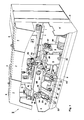
- the purpose of the machine shown is to round box bodies 1 from flat, rectangular sheet metal blanks and to weld their longitudinal edges 2 to one another.
- the machine has an elongated machine bed 3 which is delimited at its ends by end walls 4 and which is divided by intermediate walls 5.
- a switch box 8 is connected to an end region of the frame 6 on its side facing away from the machine bed 3.
- a housing 9 adjoins the other end region on the same side.
- a stacker 10 Arranged on the housing 9 is a stacker 10, which in the usual way is intended to take flat sheet metal plates individually from a stack and to convey them to a flexer 11, which frees each individual sheet metal plate from internal stresses by multiple bending and feeds it to a round station 12.
- a wedge 13 is arranged at the transition between the flexer 11 and the round station 12, via which each individual sheet metal plate runs between a lower roller 14 and an upper roller 15.
- the lower roller 14 is mounted on an arm 16 which is fastened to the frame 6 with one of its ends and extends horizontally from there via the round station 12 along a large part of the frame 6, approximately at half its height.
- the upper roller 15 is mounted on a bracket 17 which extends above the arm 16 transversely thereto and is attached to the frame 6 with one of its ends.
- the round station 12 also includes a shell-like lower guide element 18 and two likewise shell-like upper guide elements 19, each of which has a ring-shaped cross section and are arranged around the arm 16 in such a way that each individual sheet metal plate is moved by the rollers 14 and 15 into a space between these guide elements and the arm 16 is promoted and takes the desired cylindrical shape of a can frame 1.
- the conveyor device with which the can bodies 1 are individually conveyed along the arm 16 away from the round station 12 is described below.
- the machine bed 3 is bridged by a frame 20, the shape of which is a satellite roof with an open ridge is similar.
- a frame 20 On the frame 20, two guides 21 are arranged, each extending radially towards the arm 16 on an inclined side of the frame, at right angles to one another, and inclined by 45 ° against a horizontal plane.
- a slide 22 is guided on each of the guides 21 and can be adjusted with high accuracy to adapt to can bodies 1 of different diameters by means of an actuator 23, which has, for example, a threaded spindle.
- the one of the two carriages 22, which is arranged on the operating side of the machine, that is to say the viewer of FIG. 1, can be adjusted independently of the actuating drive 23 by means of a rapid traverse drive 23 'so that the arm 16 can be released quickly, for example if Fault must be remedied.
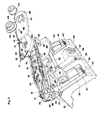
- Each of the slides 22 carries a gear 24, from which a drive shaft 25 protrudes upward.
- the drive shafts 25 lie in a common vertical plane lying transversely with respect to the arm 16 and form an angle of 45 ° with the vertical longitudinal center plane of the arm 16.
- An interchangeable strand carrier 26 is attached to the gear 24 of each of the two carriages 22 and has a certain similarity to the chain sword of a chainsaw.
- Each strand carrier 26 has a cutout 27 for the associated drive shaft 25 and also has a pair of centering holes 28 which are approximately diametrically opposite one another with respect to the cutout 27 and are each assigned to a bolt 29 arranged on the housing of the associated gearbox 24.
- Each strand carrier 26 is plugged onto the associated bolts 29, centered by them and held in place with quick-release threaded nuts (not shown).
- an endless conveyor strand 30 is guided, which in the example shown is formed by a link chain with drivers 31 arranged at regular intervals, but could also be formed, for example, by a toothed belt.
- Each conveyor line 30 runs over a pair of deflection devices 32, each of which has a sprocket in the example shown.
- the deflection devices 32 are arranged in such a way that one strand of each conveyor line 30 extends parallel to the arm 16, and the overall conveyor line is always kept uniformly tensioned.
- Each conveyor train 30 is also assigned a drive wheel 33, also a chain wheel in the example shown, which can be plugged onto the associated drive shaft 25 and attached to it by means of a quick-release coupling 34.
- the drive shafts 25 of the two carriages 22 are connected to a respective drive shaft 35 by the respective associated gear 24 and via this to a further drive shaft 36.
- the two cardan shafts 36 start from a branching gear 37 which is fastened to one of the intermediate walls 5 and can be driven by a motor 38.
- the motor 38 also drives the flexer 11 and the rollers 14 and 15 in the round station 12 via a cardan shaft 39.
- These conveyor elements responsible for feeding the sheet metal blanks to the round station 12 are therefore synchronized with the conveyor lines 30. In this way, it is ensured that each can body 11, which has been rounded in the round station 12 around the arm 16, is gripped by two drivers 31, each of which belongs to one of the two conveyor lines 30 and the can body along the arm 16 of move the round station 12 away.
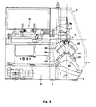
- a further, similar frame 40 is arranged on the machine bed 3 at a distance downstream from the frame 20.
- the frame 40 has a pair of guides 41, which correspond to the guides 21 and each guide a carriage 42, which can be adjusted by means of an actuator 43 in the form of a threaded spindle with high accuracy to adapt to can bodies 1 of different diameters.
- the one of the two carriages 42 which is arranged on the operating side of the machine, that is to say the viewer of FIG. 1, can also be adjusted independently of the actuator 43 by means of a rapid traverse drive 43 'from the arm 16 so that it can be quickly accessed can without changing anything on the setting of the actuator 43.
- the two rapid traverse drives 23 'and 43' can always be operated together and in the same direction.
- Each of the two slides 42 carries a gear 44 with a drive shaft 45.
- Each of the two gears 44 connects the two associated cardan shafts 35 and 36 to one another and to the relevant drive shaft 45.
- a strand carrier 46 is attached to the gear 44 of each of the two slides 42, which for this purpose has a recess 47 for the drive shaft 45 and a pair of holes 48 for a pair of bolts 49 fastened to the gear 44 and is easily replaceable.
- Each strand carrier 46 carries a conveyor strand 50, which in turn is formed by a link chain with drivers 51.
- Each of the two conveyor lines 50 runs over a pair of deflection devices 52 and can be driven by a drive wheel 53 which can be plugged onto the associated drive shaft 45 and fastened to it by means of a quick-release coupling 54.
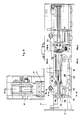
- the frames 20 and 40 are adjustable in the manner of bed slides along the machine bed 3, that is to say parallel to the arm 16. For common movements, the two frames 20 and 40 are connected to one another by a length-adjustable threaded rod 55. On the frame 40, a gear transmission 56 is arranged, which can be driven by a handwheel 57 and cooperates with a rack, not shown, attached to the machine bed 3 in order to adjust the frames 20 and 40.
- the described lower guide element 18 in the round station 12 is fastened to a support 58, which in turn is adjustable by means of a clamping strip 59 on the housing of the gear 24 on that of the two slides 22, which is arranged on the operating side of the machine and, as described, in Rapid traverse is adjustable.
- This carriage 22 is shown in a rest position remote from the arm 16 in FIG. 5b. The distance between the working position and the rest position of the carriage 22 in question is indicated by an arrow.
- each roller support 61 is adjustably fastened to a downwardly open U-rail 64 via supports 63, and this is in turn held on an upwardly open U-rail 65, which in turn is quickly releasably clamped to a bracket 67 by means of a handle 66.
- Each of the brackets 67 is attached to the gear 44 on that of the two carriages 42 which is on the operator arranged on the machine side and, as described, is also adjustable in rapid traverse.
- This carriage 42 is also shown in FIG. 7 in a rest position remote from the arm 16. The distance between the working position and the rest position of the carriage 42 in question is again indicated by an arrow.
- a Z-rail 68 is fastened on the upper side of the arm 16, which leads the longitudinal edges 2 of the can bodies 1 in the usual manner.
- a pair of busbars 69 Arranged parallel to the Z-rail 68 and at the same height as this is a pair of busbars 69 which supply a welding station 70 with current.
- the welding station 70 is of a conventional type and has, in particular, a pair of electrode rollers 71 and 72 for welding the longitudinal edges 2 of the can bodies 1.
- the machine equipped according to FIG. 5a for the production of large can bodies 1 is to be converted in such a way that it can produce much smaller can bodies, and if such a conversion is not possible simply by adjusting the slides 22 and 42, the strand carriers 26 originally used become and 46 together with their conveying strands 30 and 50 and deflection devices 32 and 52, if necessary including the respectively associated drive wheel 33 and 53, are replaced by correspondingly differently designed strand carriers 26 and 46. If necessary, the guide elements 18, 19 and 60 are also replaced.
Landscapes
- Engineering & Computer Science (AREA)
- Mechanical Engineering (AREA)
- Specific Conveyance Elements (AREA)
- Wire Processing (AREA)
- Butt Welding And Welding Of Specific Article (AREA)
- Details Of Rigid Or Semi-Rigid Containers (AREA)
- Branching, Merging, And Special Transfer Between Conveyors (AREA)
- Intermediate Stations On Conveyors (AREA)
- Lining Or Joining Of Plastics Or The Like (AREA)
- Chain Conveyers (AREA)
- Packaging Of Special Articles (AREA)
- Bending Of Plates, Rods, And Pipes (AREA)
Applications Claiming Priority (2)
| Application Number | Priority Date | Filing Date | Title |
|---|---|---|---|
| CH1737/87 | 1987-05-07 | ||
| CH1737/87A CH671945A5 (fr) | 1987-05-07 | 1987-05-07 |
Publications (3)
| Publication Number | Publication Date |
|---|---|
| EP0289744A2 true EP0289744A2 (fr) | 1988-11-09 |
| EP0289744A3 EP0289744A3 (en) | 1989-05-03 |
| EP0289744B1 EP0289744B1 (fr) | 1991-08-14 |
Family
ID=4217404
Family Applications (1)
| Application Number | Title | Priority Date | Filing Date |
|---|---|---|---|
| EP19880103850 Expired - Lifetime EP0289744B1 (fr) | 1987-05-07 | 1988-03-11 | Convoyeur pour les corps cylindriques des boîtes à une machine à souder les boîtes |
Country Status (17)
| Country | Link |
|---|---|
| US (1) | US4870241A (fr) |
| EP (1) | EP0289744B1 (fr) |
| JP (1) | JPS63281782A (fr) |
| KR (1) | KR920004662B1 (fr) |
| CN (1) | CN1009172B (fr) |
| AU (1) | AU602644B2 (fr) |
| BR (1) | BR8802219A (fr) |
| CA (1) | CA1283882C (fr) |
| CH (1) | CH671945A5 (fr) |
| DE (2) | DE3736002A1 (fr) |
| DK (1) | DK251488A (fr) |
| ES (1) | ES2025230B3 (fr) |
| FI (1) | FI882069A7 (fr) |
| GR (1) | GR3003032T3 (fr) |
| NO (1) | NO167554C (fr) |
| RU (1) | RU1787094C (fr) |
| ZA (1) | ZA882554B (fr) |
Cited By (4)
| Publication number | Priority date | Publication date | Assignee | Title |
|---|---|---|---|---|
| AU602644B2 (en) * | 1987-05-07 | 1990-10-18 | Elpatronic A.G. | Conveyor device for can bodies in a can welding machine |
| EP0523377A1 (fr) * | 1991-07-19 | 1993-01-20 | Elpatronic Ag | Dispositif d'amenée de tôles minces à une machine de soudage de boîtes |
| EP0696486A1 (fr) * | 1994-08-10 | 1996-02-14 | Elpatronic Ag | Procédé et dispositif pour cintrer des pièces en tÔle |
| WO2008144947A1 (fr) * | 2007-05-30 | 2008-12-04 | Soudronic Ag | Procédé et dispositif pour ajuster un poste d'assouplissement pendant le cintrage de tôles |
Families Citing this family (14)
| Publication number | Priority date | Publication date | Assignee | Title |
|---|---|---|---|---|
| US5209625A (en) * | 1989-08-22 | 1993-05-11 | Elpatronic Ag | Apparatus for rounding and conveying onwards sheet-metal blanks for can bodies |
| CH680714A5 (fr) * | 1989-08-22 | 1992-10-30 | Elpatronic Ag | |
| DE3932551C2 (de) * | 1989-09-29 | 1998-07-09 | Krupp Kunststofftechnik Gmbh | Einrichtung zum Zuführen gerundeter Dosenzargen in den Bereich einer Schweißeinheit |
| EP0714839B1 (fr) | 1994-11-28 | 1998-08-05 | Elpatronic Ag | Procédé pour mettre en service ou adapter une machine pour souder des pièces brutes de boites et un magasin modulaire pour mise en oeuvre dudit procédé |
| DE29813669U1 (de) | 1998-07-31 | 1999-12-23 | KUKA Schweissanlagen GmbH, 86165 Augsburg | Flexible Arbeitsstation |
| US7992276B2 (en) * | 2006-10-24 | 2011-08-09 | GM Global Technology Operations LLC | Fixture exchange rail system and method of use |
| CN105033428B (zh) * | 2015-07-02 | 2017-10-13 | 东莞市联洲知识产权运营管理有限公司 | 一种焊接设备 |
| CH713656A1 (de) * | 2017-03-29 | 2018-10-15 | Can Man Ag | Verfahren zum Runden von Blechzuschnitten für Gebinde und eine Längsnaht-Schweissmaschine für die Herstellung von Dosenzargen mit einer Rundstation. |
| CN109500281B (zh) * | 2018-12-24 | 2023-09-29 | 深圳华特容器股份有限公司 | 可调式罐身拓斜机 |
| CN110102927B (zh) * | 2019-05-17 | 2024-07-19 | 佛山市顺德区杰峰工业自动化有限公司 | 一种罐体自动焊接设备 |
| CN112960350B (zh) * | 2021-02-02 | 2024-06-11 | 广州市通海金属制品有限公司 | 一种金属罐加工生产线 |
| CN114535887B (zh) * | 2022-04-24 | 2022-06-28 | 深圳市米里汽车电子有限公司 | 一种用于汽车座椅骨架的焊接装置 |
| CN114985181B (zh) * | 2022-05-18 | 2023-05-30 | 珠海格力智能装备有限公司 | 喷漆烘干生产线 |
| CN116924034A (zh) * | 2023-07-27 | 2023-10-24 | 昇兴(郑州)包装有限公司 | 5800焊机及其推料机构 |
Family Cites Families (13)
| Publication number | Priority date | Publication date | Assignee | Title |
|---|---|---|---|---|
| US2236747A (en) * | 1939-02-23 | 1941-04-01 | Cameron Can Machinery Co | Feeding device for can bodies |
| US2432490A (en) * | 1944-10-30 | 1947-12-09 | Taylor Winfield Corp | Tubular body maker and conveyor |
| US3584178A (en) * | 1969-04-09 | 1971-06-08 | Nat Can Corp | Can body welding machine |
| US4050394A (en) * | 1976-04-09 | 1977-09-27 | Libby, Mcneil & Libby | Can fabrication system |
| CH621499A5 (fr) * | 1977-06-10 | 1981-02-13 | Paul Opprecht | |
| NL183178C (nl) * | 1978-06-21 | 1988-08-16 | Hoogovens Ijmuiden Bv | Samengestelde transporteur. |
| US4497995A (en) * | 1982-04-15 | 1985-02-05 | Sws Incorporated | Apparatus for continuously advancing and welding metal can bodies and the like |
| IT1169112B (it) * | 1983-02-24 | 1987-05-27 | Augusto Marchetti | Macchina nastratrice con unita' di trascinamento a distanza regolabile |
| US4574176A (en) * | 1983-11-28 | 1986-03-04 | Sws Incorporated | Method and apparatus for pulsed high energy density welding |
| US4694953A (en) * | 1985-06-12 | 1987-09-22 | Automation Service Equipment, Inc. | Drive for double gripper chain conveyor |
| FR2586657B1 (fr) * | 1985-09-04 | 1991-03-22 | Lapouyade Sa | Dispositif de prehension de supports ou de conteneurs de charges |
| CH667411A5 (de) * | 1985-09-09 | 1988-10-14 | Elpatronic Ag | Zargenfuehrung an einer maschine zum stumpfschweissen von dosenzargen. |
| CH671945A5 (fr) * | 1987-05-07 | 1989-10-13 | Elpatronic Ag |
-
1987
- 1987-05-07 CH CH1737/87A patent/CH671945A5/de not_active IP Right Cessation
- 1987-10-23 DE DE19873736002 patent/DE3736002A1/de active Granted
-
1988
- 1988-03-11 EP EP19880103850 patent/EP0289744B1/fr not_active Expired - Lifetime
- 1988-03-11 DE DE8888103850T patent/DE3864182D1/de not_active Expired - Lifetime
- 1988-03-11 ES ES88103850T patent/ES2025230B3/es not_active Expired - Lifetime
- 1988-03-25 US US07/173,279 patent/US4870241A/en not_active Expired - Lifetime
- 1988-04-11 KR KR1019880004099A patent/KR920004662B1/ko not_active Expired
- 1988-04-12 ZA ZA882554A patent/ZA882554B/xx unknown
- 1988-04-18 AU AU14712/88A patent/AU602644B2/en not_active Ceased
- 1988-04-18 CA CA000564360A patent/CA1283882C/fr not_active Expired - Lifetime
- 1988-04-25 CN CN88102515A patent/CN1009172B/zh not_active Expired
- 1988-04-28 JP JP63104404A patent/JPS63281782A/ja active Granted
- 1988-05-04 FI FI882069A patent/FI882069A7/fi not_active IP Right Cessation
- 1988-05-06 BR BR8802219A patent/BR8802219A/pt not_active IP Right Cessation
- 1988-05-06 NO NO881988A patent/NO167554C/no unknown
- 1988-05-06 DK DK251488A patent/DK251488A/da not_active Application Discontinuation
- 1988-05-07 RU SU884355640A patent/RU1787094C/ru active
-
1991
- 1991-10-31 GR GR91401177T patent/GR3003032T3/el unknown
Cited By (4)
| Publication number | Priority date | Publication date | Assignee | Title |
|---|---|---|---|---|
| AU602644B2 (en) * | 1987-05-07 | 1990-10-18 | Elpatronic A.G. | Conveyor device for can bodies in a can welding machine |
| EP0523377A1 (fr) * | 1991-07-19 | 1993-01-20 | Elpatronic Ag | Dispositif d'amenée de tôles minces à une machine de soudage de boîtes |
| EP0696486A1 (fr) * | 1994-08-10 | 1996-02-14 | Elpatronic Ag | Procédé et dispositif pour cintrer des pièces en tÔle |
| WO2008144947A1 (fr) * | 2007-05-30 | 2008-12-04 | Soudronic Ag | Procédé et dispositif pour ajuster un poste d'assouplissement pendant le cintrage de tôles |
Also Published As
| Publication number | Publication date |
|---|---|
| NO881988L (no) | 1988-11-08 |
| DE3864182D1 (de) | 1991-09-19 |
| FI882069A7 (fi) | 1988-11-08 |
| CN88102515A (zh) | 1988-11-23 |
| NO167554C (no) | 1991-11-20 |
| EP0289744B1 (fr) | 1991-08-14 |
| JPH0337838B2 (fr) | 1991-06-06 |
| DE3736002C2 (fr) | 1989-02-16 |
| FI882069A0 (fi) | 1988-05-04 |
| DK251488A (da) | 1988-11-08 |
| RU1787094C (ru) | 1993-01-07 |
| ES2025230B3 (es) | 1992-03-16 |
| CH671945A5 (fr) | 1989-10-13 |
| KR880013634A (ko) | 1988-12-21 |
| KR920004662B1 (ko) | 1992-06-13 |
| BR8802219A (pt) | 1988-12-06 |
| GR3003032T3 (en) | 1993-02-17 |
| US4870241A (en) | 1989-09-26 |
| EP0289744A3 (en) | 1989-05-03 |
| NO881988D0 (no) | 1988-05-06 |
| AU1471288A (en) | 1988-11-10 |
| AU602644B2 (en) | 1990-10-18 |
| DK251488D0 (da) | 1988-05-06 |
| CN1009172B (zh) | 1990-08-15 |
| JPS63281782A (ja) | 1988-11-18 |
| NO167554B (no) | 1991-08-12 |
| ZA882554B (en) | 1989-12-27 |
| DE3736002A1 (de) | 1988-11-17 |
| CA1283882C (fr) | 1991-05-07 |
Similar Documents
| Publication | Publication Date | Title |
|---|---|---|
| EP0289744B1 (fr) | Convoyeur pour les corps cylindriques des boîtes à une machine à souder les boîtes | |
| EP1849536B1 (fr) | Machine de cintrage pour des pièces en forme de barre, telle que du fil ou du tube | |
| EP0289748B1 (fr) | Outil de calibrage d'une machine pour souder longitudinalement les corps arrondis cylindriques des boîtes | |
| EP0623542A1 (fr) | Dispositif pour empiler un chant de feuilles imprimées | |
| EP0243795B1 (fr) | Dispositif pour guider des viroles arrondies à travers une zône de soudage | |
| CH679219A5 (fr) | ||
| EP0241449B1 (fr) | Machine à souder par résistance par points nombreuses | |
| DE9414501U1 (de) | Bearbeitungsmaschine mit relativverschiebbaren Drehvorrichtungen | |
| DE2849751C2 (de) | Vorrichtung zum Vereinzeln von ein loses Bündel bildenden abgelängten Drähten, insbesondere zwechs Drahtzufuhr zu einer Verarbeitungsmaschine | |
| EP0420018B1 (fr) | Dispositif pour l'amenée de boîtes arrondies à une unité de soudage | |
| DE102010005757B3 (de) | Vorrichtung und Verfahren zum Führen von miteinander entlang ihrer Längskanten zu fügender Bänder | |
| EP1351783A1 (fr) | Dispositif de coupe transversale de bandes metalliques | |
| EP0212620B1 (fr) | Machine pour souder ensemble les bords longitudinaux de pièces brutes de boîtes arrondies | |
| EP0182071B1 (fr) | Dispositif pour empiler des articles plats munis de deux trous de position, de préférence des sacs fabriqués à partir de feuilles en matière plastique | |
| DE69129077T2 (de) | Verfahren und vorrichtung zum schneiden von rohren, in welchem die rohre mittels einer rotierenden festhaltplatte in schneidposition gebracht werden | |
| EP3369685A1 (fr) | Dispositif de transport de pièces allongées à un point de réception et de dépôt des dites pièces allongées audit point de réception | |
| EP0054890A1 (fr) | Transporteur pour pièces à usiner, en particulier pour des petites pièces | |
| DE509520C (de) | Falzmaschine | |
| DE4232530C2 (de) | Richttisch | |
| EP0499797A1 (fr) | Dispositif d'alignement pour bois à usiner | |
| DE2600191C2 (de) | Transport- und Wendeeinrichtung für eine Mutternpresse | |
| DE2534753A1 (de) | Kartonherstellungsmaschine | |
| WO2023057465A1 (fr) | Dispositif de transport de produits pour fournir des produits alimentaires à une unité de tranchage | |
| DE3135277A1 (de) | Rotations-schneidanlage | |
| DE1435070C (de) | Plissiermaschine |
Legal Events
| Date | Code | Title | Description |
|---|---|---|---|
| PUAI | Public reference made under article 153(3) epc to a published international application that has entered the european phase |
Free format text: ORIGINAL CODE: 0009012 |
|
| AK | Designated contracting states |
Kind code of ref document: A2 Designated state(s): BE CH DE ES FR GB GR IT LI NL SE |
|
| PUAL | Search report despatched |
Free format text: ORIGINAL CODE: 0009013 |
|
| AK | Designated contracting states |
Kind code of ref document: A3 Designated state(s): BE CH DE ES FR GB GR IT LI NL SE |
|
| 17P | Request for examination filed |
Effective date: 19890410 |
|
| 17Q | First examination report despatched |
Effective date: 19900502 |
|
| GRAA | (expected) grant |
Free format text: ORIGINAL CODE: 0009210 |
|
| AK | Designated contracting states |
Kind code of ref document: B1 Designated state(s): BE CH DE ES FR GB GR IT LI NL SE |
|
| GBT | Gb: translation of ep patent filed (gb section 77(6)(a)/1977) | ||
| ITF | It: translation for a ep patent filed | ||
| REF | Corresponds to: |
Ref document number: 3864182 Country of ref document: DE Date of ref document: 19910919 |
|
| ET | Fr: translation filed | ||
| RAP4 | Party data changed (patent owner data changed or rights of a patent transferred) |
Owner name: ELPATRONIC AG |
|
| REG | Reference to a national code |
Ref country code: ES Ref legal event code: FG2A Ref document number: 2025230 Country of ref document: ES Kind code of ref document: B3 |
|
| PLBE | No opposition filed within time limit |
Free format text: ORIGINAL CODE: 0009261 |
|
| STAA | Information on the status of an ep patent application or granted ep patent |
Free format text: STATUS: NO OPPOSITION FILED WITHIN TIME LIMIT |
|
| 26N | No opposition filed | ||
| REG | Reference to a national code |
Ref country code: GR Ref legal event code: FG4A Free format text: 3003032 |
|
| PGFP | Annual fee paid to national office [announced via postgrant information from national office to epo] |
Ref country code: GR Payment date: 19931223 Year of fee payment: 7 |
|
| EAL | Se: european patent in force in sweden |
Ref document number: 88103850.9 |
|
| PGFP | Annual fee paid to national office [announced via postgrant information from national office to epo] |
Ref country code: BE Payment date: 19950220 Year of fee payment: 8 |
|
| PGFP | Annual fee paid to national office [announced via postgrant information from national office to epo] |
Ref country code: ES Payment date: 19950307 Year of fee payment: 8 |
|
| PG25 | Lapsed in a contracting state [announced via postgrant information from national office to epo] |
Ref country code: GR Free format text: THE PATENT HAS BEEN ANNULLED BY A DECISION OF A NATIONAL AUTHORITY Effective date: 19950930 |
|
| REG | Reference to a national code |
Ref country code: GR Ref legal event code: MM2A Free format text: 3003032 |
|
| PG25 | Lapsed in a contracting state [announced via postgrant information from national office to epo] |
Ref country code: ES Free format text: LAPSE BECAUSE OF NON-PAYMENT OF DUE FEES Effective date: 19960312 |
|
| PG25 | Lapsed in a contracting state [announced via postgrant information from national office to epo] |
Ref country code: BE Effective date: 19960331 |
|
| BERE | Be: lapsed |
Owner name: ELPATRONIC A.G. Effective date: 19960331 |
|
| REG | Reference to a national code |
Ref country code: ES Ref legal event code: FD2A Effective date: 19990405 |
|
| REG | Reference to a national code |
Ref country code: CH Ref legal event code: PFA Free format text: ELPATRONIC AG,HERTIZENTRUM 6,6303 ZUG (CH) TRANSFER- ELPATRONIC AG,INDUSTRIESTRASSE 35,8962 BERGDIETIKON (CH) |
|
| REG | Reference to a national code |
Ref country code: GB Ref legal event code: IF02 |
|
| PGFP | Annual fee paid to national office [announced via postgrant information from national office to epo] |
Ref country code: NL Payment date: 20060314 Year of fee payment: 19 |
|
| PGFP | Annual fee paid to national office [announced via postgrant information from national office to epo] |
Ref country code: GB Payment date: 20060322 Year of fee payment: 19 |
|
| PG25 | Lapsed in a contracting state [announced via postgrant information from national office to epo] |
Ref country code: SE Free format text: LAPSE BECAUSE OF NON-PAYMENT OF DUE FEES Effective date: 20070312 |
|
| PGFP | Annual fee paid to national office [announced via postgrant information from national office to epo] |
Ref country code: CH Payment date: 20070314 Year of fee payment: 20 |
|
| PGFP | Annual fee paid to national office [announced via postgrant information from national office to epo] |
Ref country code: DE Payment date: 20070316 Year of fee payment: 20 |
|
| EUG | Se: european patent has lapsed | ||
| GBPC | Gb: european patent ceased through non-payment of renewal fee |
Effective date: 20070311 |
|
| NLV4 | Nl: lapsed or anulled due to non-payment of the annual fee |
Effective date: 20071001 |
|
| PGFP | Annual fee paid to national office [announced via postgrant information from national office to epo] |
Ref country code: IT Payment date: 20070613 Year of fee payment: 20 |
|
| PG25 | Lapsed in a contracting state [announced via postgrant information from national office to epo] |
Ref country code: NL Free format text: LAPSE BECAUSE OF NON-PAYMENT OF DUE FEES Effective date: 20071001 |
|
| PGFP | Annual fee paid to national office [announced via postgrant information from national office to epo] |
Ref country code: SE Payment date: 20060314 Year of fee payment: 19 |
|
| REG | Reference to a national code |
Ref country code: CH Ref legal event code: PL |
|
| PG25 | Lapsed in a contracting state [announced via postgrant information from national office to epo] |
Ref country code: GB Free format text: LAPSE BECAUSE OF NON-PAYMENT OF DUE FEES Effective date: 20070311 |
|
| PGFP | Annual fee paid to national office [announced via postgrant information from national office to epo] |
Ref country code: FR Payment date: 20070319 Year of fee payment: 20 |