EP0243814A2 - Procédé et double bande sans fin pour la production de plaque en mousse munie de couches de revêtement à partir d'un mélange réactif coulable - Google Patents
Procédé et double bande sans fin pour la production de plaque en mousse munie de couches de revêtement à partir d'un mélange réactif coulable Download PDFInfo
- Publication number
- EP0243814A2 EP0243814A2 EP87105655A EP87105655A EP0243814A2 EP 0243814 A2 EP0243814 A2 EP 0243814A2 EP 87105655 A EP87105655 A EP 87105655A EP 87105655 A EP87105655 A EP 87105655A EP 0243814 A2 EP0243814 A2 EP 0243814A2
- Authority
- EP
- European Patent Office
- Prior art keywords
- conveyor belt
- drive
- regulated
- belts
- reaction mixture
- Prior art date
- Legal status (The legal status is an assumption and is not a legal conclusion. Google has not performed a legal analysis and makes no representation as to the accuracy of the status listed.)
- Withdrawn
Links
- 239000006260 foam Substances 0.000 title claims abstract description 13
- 238000000034 method Methods 0.000 title claims description 11
- 239000011541 reaction mixture Substances 0.000 title claims description 5
- 238000004519 manufacturing process Methods 0.000 title claims description 4
- 238000010924 continuous production Methods 0.000 claims abstract description 3
- 230000001105 regulatory effect Effects 0.000 claims description 9
- 230000009969 flowable effect Effects 0.000 claims description 4
- 238000000576 coating method Methods 0.000 abstract 1
- 206010038743 Restlessness Diseases 0.000 description 1
- 229910000831 Steel Inorganic materials 0.000 description 1
- 238000006243 chemical reaction Methods 0.000 description 1
- 230000008878 coupling Effects 0.000 description 1
- 238000010168 coupling process Methods 0.000 description 1
- 238000005859 coupling reaction Methods 0.000 description 1
- 238000009826 distribution Methods 0.000 description 1
- 239000004744 fabric Substances 0.000 description 1
- 230000007257 malfunction Effects 0.000 description 1
- 238000005259 measurement Methods 0.000 description 1
- 238000003825 pressing Methods 0.000 description 1
- 230000002035 prolonged effect Effects 0.000 description 1
- 230000000630 rising effect Effects 0.000 description 1
- 239000010959 steel Substances 0.000 description 1
Images
Classifications
-
- B—PERFORMING OPERATIONS; TRANSPORTING
- B29—WORKING OF PLASTICS; WORKING OF SUBSTANCES IN A PLASTIC STATE IN GENERAL
- B29C—SHAPING OR JOINING OF PLASTICS; SHAPING OF MATERIAL IN A PLASTIC STATE, NOT OTHERWISE PROVIDED FOR; AFTER-TREATMENT OF THE SHAPED PRODUCTS, e.g. REPAIRING
- B29C44/00—Shaping by internal pressure generated in the material, e.g. swelling or foaming ; Producing porous or cellular expanded plastics articles
- B29C44/34—Auxiliary operations
- B29C44/60—Measuring, controlling or regulating
-
- B—PERFORMING OPERATIONS; TRANSPORTING
- B29—WORKING OF PLASTICS; WORKING OF SUBSTANCES IN A PLASTIC STATE IN GENERAL
- B29C—SHAPING OR JOINING OF PLASTICS; SHAPING OF MATERIAL IN A PLASTIC STATE, NOT OTHERWISE PROVIDED FOR; AFTER-TREATMENT OF THE SHAPED PRODUCTS, e.g. REPAIRING
- B29C44/00—Shaping by internal pressure generated in the material, e.g. swelling or foaming ; Producing porous or cellular expanded plastics articles
- B29C44/20—Shaping by internal pressure generated in the material, e.g. swelling or foaming ; Producing porous or cellular expanded plastics articles for articles of indefinite length
- B29C44/32—Incorporating or moulding on preformed parts, e.g. linings, inserts or reinforcements
- B29C44/321—Incorporating or moulding on preformed parts, e.g. linings, inserts or reinforcements the preformed part being a lining, e.g. a film or a support lining
-
- B—PERFORMING OPERATIONS; TRANSPORTING
- B29—WORKING OF PLASTICS; WORKING OF SUBSTANCES IN A PLASTIC STATE IN GENERAL
- B29L—INDEXING SCHEME ASSOCIATED WITH SUBCLASS B29C, RELATING TO PARTICULAR ARTICLES
- B29L2009/00—Layered products
Definitions
- the invention relates to a method and a double conveyor belt for producing foam sheets provided with cover layers from a flowable reaction mixture on a double conveyor belt consisting of a lower conveyor belt and an upper conveyor belt, which are driven uniformly.
- the double conveyor belt has been switched off for a period of time after a certain operating time, as soon as the faults have increased.
- the transportation belts were then able to cool down again and when the machine was used again, the error rocked up again.
- the object is to find a method or to improve the known double conveyor belt in such a way that smooth operation is ensured by avoiding any relative speed between the conveyor belts.
- both the drive power of the upper conveyor belt and that of the lower conveyor belt are regulated.
- the drive power of one conveyor belt is kept constant and that of the other conveyor belt is regulated.
- the currents absorbed by the electric drive motors are preferably used as control variables.
- the drive torques are recorded as control variables.
- the thrust force of the drivers pressing against the stops can also be recorded as a controlled variable.
- the double conveyor belt for the continuous production of foam webs provided with cover layers from a flowable reaction mixture starts from an upper conveyor belt provided with a drive and a lower conveyor belt.
- each of the two conveyor belts is assigned its own electric drive motor, which is mechanically decoupled from the other, and these drive motors are connected to one another via a control system.
- the drive power is regulated in the sense of an exactly the same rotational speed of the conveyor belts.
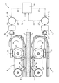
- the double conveyor belt consists of a lower conveyor belt 1 and an upper conveyor belt 2, which are driven by driver chains 3, 4. Between the conveyor belts 1, 2 there is the foam space 7 filled by a foam web 7 which is being manufactured and provided with cover layers 5, 6.
- the conveyor belts 1, 2 are guided in rails 8, 9.
- the driver chains 3, 4 are equipped with drivers 10, 11 which engage against stops 12, 13 of the conveyor belts 1, 2.
- Each drive chain 3, 4 is assigned a special drive 14, 15.
- These drives 14, 15 each consist of an electric drive motor 16, 17, a gear 18, 19, a clutch 20, 21 and a worm gear 22, 23, which mesh with a drive wheel 3, 4 driving gear 24, 25.
- a common control 26 is assigned to the drive motors 16, 17.
- the measuring point 27, 18 is placed on the output shaft of the drive motor 16, 17.
- the force acting on the stops 12, 13 by the drivers 10, 11 can also be used as a control variable.
Landscapes
- Casting Or Compression Moulding Of Plastics Or The Like (AREA)
Applications Claiming Priority (2)
| Application Number | Priority Date | Filing Date | Title |
|---|---|---|---|
| DE3614879 | 1986-05-02 | ||
| DE19863614879 DE3614879A1 (de) | 1986-05-02 | 1986-05-02 | Verfahren und doppeltransportband zum herstellen von mit deckschichten versehenen schaumstoffbahnen aus einem fliessfaehigen reaktionsgemisch |
Publications (1)
| Publication Number | Publication Date |
|---|---|
| EP0243814A2 true EP0243814A2 (fr) | 1987-11-04 |
Family
ID=6300014
Family Applications (1)
| Application Number | Title | Priority Date | Filing Date |
|---|---|---|---|
| EP87105655A Withdrawn EP0243814A2 (fr) | 1986-05-02 | 1987-04-16 | Procédé et double bande sans fin pour la production de plaque en mousse munie de couches de revêtement à partir d'un mélange réactif coulable |
Country Status (2)
| Country | Link |
|---|---|
| EP (1) | EP0243814A2 (fr) |
| DE (1) | DE3614879A1 (fr) |
Cited By (1)
| Publication number | Priority date | Publication date | Assignee | Title |
|---|---|---|---|---|
| EP0286571A3 (fr) * | 1987-04-06 | 1991-07-24 | UNITED TECHNOLOGIES AUTOMOTIVE, Inc. | Noyaux d'insonorisation mousseux en forme de panneaux et procédé de fabrication |
-
1986
- 1986-05-02 DE DE19863614879 patent/DE3614879A1/de not_active Withdrawn
-
1987
- 1987-04-16 EP EP87105655A patent/EP0243814A2/fr not_active Withdrawn
Cited By (1)
| Publication number | Priority date | Publication date | Assignee | Title |
|---|---|---|---|---|
| EP0286571A3 (fr) * | 1987-04-06 | 1991-07-24 | UNITED TECHNOLOGIES AUTOMOTIVE, Inc. | Noyaux d'insonorisation mousseux en forme de panneaux et procédé de fabrication |
Also Published As
| Publication number | Publication date |
|---|---|
| DE3614879A1 (de) | 1987-11-05 |
Similar Documents
| Publication | Publication Date | Title |
|---|---|---|
| DE2933017C2 (de) | Bandspeicherantrieb | |
| DE102007021681B3 (de) | Schrittschaltdrehtisch | |
| DE69417136T2 (de) | Bewegende Gehsteige mit variabler Geschwindigkeit | |
| EP0209609B1 (fr) | Machine de mise en forme à double bande sans fin | |
| CH664053A5 (de) | Verfahren und antriebssteuervorrichtung zur einflussnahme auf das hochfahren und auslaufen von zwei asynchronmotoren. | |
| DE3835102C2 (fr) | ||
| WO2006063641A1 (fr) | Dispositif et procede pour entrainer un ensemble cylindre de prechauffage dans un dispositif de calandrage | |
| DE2417570A1 (de) | Einrichtung zur stufenlosen regelung der spinn- oder zwirndrehungen bei spinnoder zwirnmaschinen | |
| EP1044108B1 (fr) | Dispositif pour l'entrainement d'une feuille continue | |
| EP0243814A2 (fr) | Procédé et double bande sans fin pour la production de plaque en mousse munie de couches de revêtement à partir d'un mélange réactif coulable | |
| DE3230363A1 (de) | Verfahren und vorrichtung zum antreiben und synchronisieren von walzen | |
| EP1919804A1 (fr) | Convoyeur | |
| EP0952096A1 (fr) | Dispositif pour deplacer une charge sur un trajet de transport | |
| EP1394083B1 (fr) | Dispositif de transport d'objets | |
| EP3592530B1 (fr) | Système d'étirage de film | |
| DE682191C (de) | Vorrichtung zum Verstellen der Einlasswaende von Gewebespannmaschinen | |
| DE970131C (de) | Rauhmaschine | |
| DE1047629B (de) | Differential-Regeleinrichtung | |
| DE10329218A1 (de) | Hotflue | |
| DE3005831C2 (de) | Spann-, Trocken- und/oder Fixiermaschine für bahnförmiges Gut | |
| DE69315867T2 (de) | Drehmaschine für Eisenbahnräder | |
| DE1704739C3 (de) | Einrichtung zur aufeinanderfolgenden Zuführung von Außenschichtplatten zu einer Ausschäumvorrichtung | |
| DE2221199C2 (de) | Flaschenbehandlungsmaschine, insbesondere Etikettiermaschine | |
| DE2849552A1 (de) | Pressenstrasse | |
| DE19609748C2 (de) | Maschine zum Formen von Glasprodukten durch Zentrifugieren |
Legal Events
| Date | Code | Title | Description |
|---|---|---|---|
| PUAI | Public reference made under article 153(3) epc to a published international application that has entered the european phase |
Free format text: ORIGINAL CODE: 0009012 |
|
| 17P | Request for examination filed |
Effective date: 19870416 |
|
| AK | Designated contracting states |
Kind code of ref document: A2 Designated state(s): DE FR GB |
|
| STAA | Information on the status of an ep patent application or granted ep patent |
Free format text: STATUS: THE APPLICATION HAS BEEN WITHDRAWN |
|
| 18W | Application withdrawn |
Withdrawal date: 19880722 |
|
| RIN1 | Information on inventor provided before grant (corrected) |
Inventor name: SULZBACH, HANS-MICHAEL Inventor name: PROKSA, FERDINAND, DR. |