EP0243821B1 - Système d'asservissement pour disque d'enregistrement de données - Google Patents
Système d'asservissement pour disque d'enregistrement de données Download PDFInfo
- Publication number
- EP0243821B1 EP0243821B1 EP87105701A EP87105701A EP0243821B1 EP 0243821 B1 EP0243821 B1 EP 0243821B1 EP 87105701 A EP87105701 A EP 87105701A EP 87105701 A EP87105701 A EP 87105701A EP 0243821 B1 EP0243821 B1 EP 0243821B1
- Authority
- EP
- European Patent Office
- Prior art keywords
- head
- track
- signal
- actuator
- input signal
- Prior art date
- Legal status (The legal status is an assumption and is not a legal conclusion. Google has not performed a legal analysis and makes no representation as to the accuracy of the status listed.)
- Expired - Lifetime
Links
- 230000006870 function Effects 0.000 claims description 37
- 230000001133 acceleration Effects 0.000 claims description 25
- 238000000034 method Methods 0.000 claims description 15
- 238000012937 correction Methods 0.000 claims description 8
- 230000003252 repetitive effect Effects 0.000 claims description 5
- 230000010354 integration Effects 0.000 claims description 3
- 230000004044 response Effects 0.000 claims description 2
- 238000006243 chemical reaction Methods 0.000 claims 4
- 230000000694 effects Effects 0.000 description 7
- 238000010586 diagram Methods 0.000 description 6
- 238000005070 sampling Methods 0.000 description 6
- 238000012886 linear function Methods 0.000 description 5
- 238000005259 measurement Methods 0.000 description 4
- 230000001052 transient effect Effects 0.000 description 4
- 238000013461 design Methods 0.000 description 2
- 206010067482 No adverse event Diseases 0.000 description 1
- 230000002411 adverse Effects 0.000 description 1
- 238000004364 calculation method Methods 0.000 description 1
- 230000008859 change Effects 0.000 description 1
- 239000004020 conductor Substances 0.000 description 1
- 230000001934 delay Effects 0.000 description 1
- 230000004069 differentiation Effects 0.000 description 1
- 238000010348 incorporation Methods 0.000 description 1
- 238000012986 modification Methods 0.000 description 1
- 230000004048 modification Effects 0.000 description 1
- 230000008569 process Effects 0.000 description 1
- 238000012827 research and development Methods 0.000 description 1
Images



Classifications
-
- G—PHYSICS
- G11—INFORMATION STORAGE
- G11B—INFORMATION STORAGE BASED ON RELATIVE MOVEMENT BETWEEN RECORD CARRIER AND TRANSDUCER
- G11B5/00—Recording by magnetisation or demagnetisation of a record carrier; Reproducing by magnetic means; Record carriers therefor
- G11B5/48—Disposition or mounting of heads or head supports relative to record carriers ; arrangements of heads, e.g. for scanning the record carrier to increase the relative speed
- G11B5/58—Disposition or mounting of heads or head supports relative to record carriers ; arrangements of heads, e.g. for scanning the record carrier to increase the relative speed with provision for moving the head for the purpose of maintaining alignment of the head relative to the record carrier during transducing operation, e.g. to compensate for surface irregularities of the latter or for track following
- G11B5/596—Disposition or mounting of heads or head supports relative to record carriers ; arrangements of heads, e.g. for scanning the record carrier to increase the relative speed with provision for moving the head for the purpose of maintaining alignment of the head relative to the record carrier during transducing operation, e.g. to compensate for surface irregularities of the latter or for track following for track following on disks
Definitions
- This invention relates to a servo control system for both track seeking and track following which is usable with a data recording disk file having servo information on either a dedicated servo disk surface or in sectors on a data disk surface.
- Disk files are information storage devices which utilise a rotatable disk with concentric data tracks containing the information, a head for reading or writing data onto the various tracks, and an actuator connected by a support arm assembly to the head for moving the head to the desired track and maintaining it over the track centreline during read or write operations.
- the movement of the head to a desired track is referred to as track accessing or “seeking”, while the maintaining of the head over the centreline of the desired track during a read or write operation is referred to as track "following".
- the actuator is typically a "voice coil motor” (VCM) which comprises a coil movable through the magnetic field of a permanent magnetic stator.
- VCM voice coil motor
- the application of current to the VCM causes the coil, and thus the attached head, to move radially.
- the acceleration of the coil is proportional to the applied current, so that ideally there is no current to the coil if the head is perfectly stationary over a desired track.
- a servo control system In disk files which have a relatively high density of data tracks on the disk, it is necessary to incorporate a servo control system to maintain the head precisely over the centreline of the desired track during read or write operations. This is accomplished by utilising prerecorded servo information either on a dedicated servo disk or on sectors angularly spaced and interspersed among the data on a data disk.
- the servo information sensed by the read/write head (or the dedicated servo head if a dedicated servo disk is used) is demodulated to generate a position error signal (PES) which is an indication of the position error of the head away from the nearest track centreline.
- PES position error signal
- One type of conventional servo pattern for use with either a sector servo disk or a dedicated servo disk is the quadrature pattern described by Mueller, et al. in IBM Technical Disclosure Bulletin , Vol. 21, No. 2 (February 1978) pp. 804-805.
- the quadrature pattern there are four unique track types which repeat so as to form radially repetitive four-track bands of servo information.
- the PES is used to generate track crossing pulses.
- This track crossing information together with the PES and a signal representing the desired or target track, is used to generate a total error signal.
- the total error signal is equal to the sum of the PES plus the difference between the position of the target track and the position of the actual track over which the head is located.
- the total error signal is then used in the servo feedback loop to compute the desired velocity of the head, via a reference velocity trajectory generator, to assure that the head arrives at the target track according to the optimum velocity trajectory to effect a move to the target track in minimum time.
- the computed velocity is then compared with the estimated velocity from an electronic tachometer to generate a velocity error signal to a power amplifier which in turn applies a control current to the VCM.
- An electronic tachometer for generating a velocity estimate from inputs of VCM control current and quadrature PES is described in U.S. -A- 4,246,536.
- the estimated velocity is provided by a mechanical tachometer, such as a linear variable differential transformer (LVDT).
- LVDT linear variable differential transformer
- the PES alone is used in the servo feedback loop to generate a control signal to the VCM to move the head back to the track centreline.
- the VCM is subjected to certain generally constant or very low frequency forces which tend to bias the coil, and thus the attached head, away from the desired position, i.e. the position needed to follow the desired velocity trajectory during track seeking, or the position of the centreline of the desired track during track following.
- These bias forces are caused by such things as circulating air flow passing the coil and the arm assembly which connects the head to the coil, the movement of the flexible ribbon conductor connecting the coil and arm assembly to the read/write electronics of the disk file, friction between the bearings and guide rails of the actuator, and the gravitational effect on the coil and arm assembly if the radial access direction of the VCM is not perfectly aligned horizontally.
- bias forces there is typically an input voltage offset in the power amplifier which supplies the control current to the VCM, so that even in the absence of a velocity error signal to the power amplifier, the VCM may experience a non-zero input current.
- bias forces and voltage offset have little effect on the performance of the servo control system during track seeking when the primary contribution to the total force on the actuator is that due to the current in the actuator.
- the bias forces and voltage offset are primary contributions to the PES and must be rapidly and effectively compensated by the control signal to the power amplifier to produce current in the VCM to maintain the head over the track centreline.
- One technique for rapidly forcing the total error signal to zero during track following is to incorporate an integrator for the PES into the servo feedback loop. This is accomplished by the use of a separate "stiffness" integrator which is switched into the servo feedback loop only during track following.
- the switchable stiffness integrator generates an electrical transient which occurs as a result of switching of the integrator when large system bias forces and voltage offset is present.
- the stiffness integrator must be switched in at precisely the proper moment. Both the transient caused by switching of the stiffness integrator and switching at the improper time can cause overshoot or undershoot of the head with respect to the centreline of the target track which thus delays the subsequent read or write operation.
- EPA 0003070 discloses a sampled servo system which uses a physical model of the system to overcome bandwidth constraints.
- An analog electrical equivalent of the actuator provides predictive coarse positioning, which allows the servo system to operate with a higher effective bandwidth than the frequency of servo sampling would otherwise permit. The problem of bias forces is not discussed.
- the invention seeks to provide an improved serve control system.
- the invention provides a method for controlling data track seeking and following in a disk file having a disk with serve information thereon defining data track centrelines, a head for reading samples of the servo information during rotation of the disk, an actuator connected to the head and responsive to an input signal for positioning the head to the centreline of a target track during track seeking and maintaining the head over the centreline of the target track during track following, the method comprising the steps of: generating from the servo information a sampled head position error signal (PES) representative of the position of the head relative to the centreline of the nearest track; for each PES sample: computing a measured absolute head position, relative to a fixed reference, from the sampled head position error signal (PES) and a prior predicted absolute head position; and computing an error signal based on the difference between said measured absolute head position and said prior predicted absolute head position; measuring the input signal to the actuator; estimating the absolute head position, relative to the fixed reference, and the head velocity, using said error signal, said prior predicted absolute head position, and a prior predicted velocity;
- the preferred servo control system receives as input, at discrete sample times, the PES and a digital value representative of the VCM current, and outputs, at discrete sample times, a digital control signal.
- the digital control signal is converted to an analog control signal and input to an integrating power amplifier which provides the control current input to the VCM.
- the digital control signal is generated by a microprocessor attached by a data bus to associated memory devices.
- the microprocessor computes the measured absolute head position from the PES and an estimate of VCM current equivalent to the amount of current required to compensate for bias forces acting on the actuator.
- the microprocessor computes an estimate of the absolute head position relative to a fixed reference and an estimate of the head velocity.
- a digital velocity trajectory generator provides a value representative of the optimum velocity of the head as a function of the difference between the absolute position of the target track and the estimated absolute head position.
- a velocity error is then computed as the difference between the computed estimate of head velocity and the optimum velocity from the velocity trajectory generator.
- the microprocessor also computes an estimate of head acceleration from the measured VCM current and the estimated bias force equivalent VCM current. The estimated head acceleration, together with the velocity error and a value representative of the control signal for the prior PES sample, are used to form the digital control signal.
- the estimated absolute head position, head velocity, and bias force equivalent VCM current are computed from respective predicted values of those terms.
- the predicted values are updated with each PES sample and are functions of, among other things, constants representing the digital sampling time and physical parameters of the VCM, such as frictional effects and force constants.
- the estimated values of these terms are computed with the use of an error term which is the difference between the computed measurement of absolute head position and the predicted absolute head position.
- the estimation of head acceleration is made such that, during track following when the head is generally within one-half track of the centreline of the target track, the average value of the estimated head acceleration is zero.
- the digital servo control system With the use of the digital servo control system according to the present invention, it is not necessary to measure or estimate track crossings so that the system is fully operable with either a dedicated servo disk or a data disk with sector servo information.
- the prediction of the absolute head position is made with sufficient accuracy such that the error between the measurement of the absolute head position and the predicted absolute head position is always less than a specific number of tracks. For example, when the servo control system is utilised with a quadrature pattern in which the servo information is radially repetitive in four-track bands, it is only necessary to measure the position of the head within a band without knowing in which particular band the head is located.
- the digital servo control system also includes means for computing a value representative of a correction signal to the digital control signal in order to compensate for voltage offsets to the integrating power amplifier.
- the correction signal is applied to the control signal and updated during track following.
- FIG. 1 The block diagram of Fig. 1 is an illustration of a conventional analog disk file servo control system.
- a pair of disks 10, 12 are supported on a spindle 14 of the disk file drive motor 16.
- Each of the disks 10, 12 has two surfaces 20, 22 and 24, 26, respectively.
- surface 20 on disk 10 and surfaces 24, 26 on disk 12 are data recording surfaces.
- Surface 22 on disk 10 is a dedicated servo surface and contains only prerecorded servo information.
- the servo information is recorded in concentric tracks and is typically written in such a manner that the intersections of adjacent servo tracks on servo surface 22 are radially aligned with the centrelines of the data tracks on surfaces 20, 24, and 26.
- the servo information on surface 20 may be the quadrature pattern, as described in the previously cited IBM Technical Disclosure Bulletin.
- the specific tracks on the data disks and the servo disk are accessed by heads 30, 32, 34, 36, each of which is associated with a respective disk surface and supported by an associated arm assembly.
- the heads 30, 32, 34, 36 are attached to a common accessing means or actuator, such as VCM 40.
- VCM 40 a common accessing means or actuator
- the output of the dedicated servo head 32 is supplied to an amplifier 42 and then to a demodulator 44.
- Demodulator 44 processes the servo information signal from disk surface 22 and demodulates it to generate an analog PES.
- the PES from demodulator 44 is an indication of the position of servo head 32 away from the nearest servo track centreline, and thus the position of the data heads 30, 34, 36 away from the centrelines of the nearest data tracks on the respective disk surfaces 20, 24, 26.
- Demodulator 44 also provides a track crossing pulse which is input to a difference counter 46 and, if the servo pattern is a quadrature pattern, a signal (not shown) which identifies one of the four specific track types in the quadrature pattern.
- the difference counter 46 also receives a command from the disk file control unit (not shown) indicating the target or desired track, denoted as t d . With each track crossing by the servo head 32, the track crossing pulse causes the value of t d stored in difference counter 46 to be decremented.
- the output from difference counter 46 is passed to a digital-to-analog converter (D/A) 48 which provides an analog value representative of the number of tracks to go to reach the desired track, t d - t a , where t a is the nearest actual track position of servo head 32 at the time of the PES measurement.
- D/A digital-to-analog converter
- the generation of track crossing pulses from the PES requires relatively costly and complex circuitry (not shown) in demodulator 44.
- the servo control system shown in Fig. 1 requires a dedicated servo disk and is not operable with sector servo information since during a track seek the head will typically cross numerous tracks between PES measurements.
- an alternative to direct counting of track crossings must be used to determine the number of tracks to go, t d - t a .
- the value t d - t a from D/A converter 48 is then summed in junction 50 with the PES, the output of summing junction 50 being the total error signal representative of the distance-to-go, x tg , to the centreline of the desired track.
- the distance-to-go is fed to a velocity trajectory generator (VTG) 54 after addition in summing junction 55 with the output from switch 52.
- VTG velocity trajectory generator
- switch 52 is opened and the output of stiffness integrator 53 is reset to zero.
- the output of summing junction 55 is then only x tg .
- the switch 52 is closed, the reset signal is removed from stiffness integrator 53 and stiffness integrator 53 is allowed to operate.
- switch 52 is closed the input to VTG 54 consists of x tg and the integral of x tg .
- VTG 54 computes a commanded velocity, v c , based upon the value of x tg .
- Conventional analog type velocity trajectory generators are typically either diode breakpoint or multiplier circuit implementations, both of which are described and shown as prior art in Figs. 1A and 1B of U. S. -A- 4,486,797.
- a compensator 56 Located between VTG 54 and VCM 40, as shown in Fig. 1, is a compensator 56 and an integrating power amplifier (IPA) 58.
- the compensator 56 contains circuitry having specific gain and phase shifting characteristics to assure stability and performance of the overall closed loop system.
- the output of compensator 56 is the control signal, u, which is directed to IPA 58 where the compensated control signal is integrated and amplified to generate a control current, i, to VCM 40.
- the control current to VCM 40 is a specific current level to move the coil so that the servo head 32, and thus the data heads 30, 34, 36, are moved with the desired velocity toward the centreline of the desired track.
- ETACH 60 An electronic tachometer (ETACH) 60 is located in a feedback path around the compensator 56 and IPA 58. ETACH 60 receives as inputs the VCM control current, i, from IPA 58 and the PES from demodulator 44. The output of ETACH 60 is an estimate of the velocity of the head. ETACH 60 provides a signal, v e , based upon a combination of the differentiated PES and integrated control current i. A more thorough description of ETACH 60 is set forth in the previously cited US -A- 4,246,536.
- ETACH 60 is a velocity error signal, v es , which is the difference between the commanded velocity, v c , output by VTG 54 and the estimated velocity, v e , output by ETACH 60.
- ETACH 60 continues to provide a feedback path around the IPA 58 and thus continues to generate a non-zero velocity estimate, v e .
- VTG 54 computes the velocity signal, v c , as a non-linear function of x tg by a reference curve, as explained in the prior art description of the previously cited patent US -A- 4,486,797.
- the total error signal, x tg is the sum of the PES and the computed number of tracks to go, t d - t a .
- switch 52 is closed, thus switching stiffness integrator 53 into the servo feedback loop.
- stiffness integrator 53 into the servo loop near the termination of a track seek causes a transient in the velocity command, v c , which causes overshoot or undershoot of the head with respect to the centreline of the desired track, thus delaying the subsequent read or write operation.
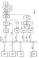
- FIG. 2 A simplified block diagram of a digital servo control system embodying the present invention is shown in Fig. 2.
- a microprocessor 80 is connected to a random access memory (RAM) 82 and a programmable read only memory (PROM) 83 via a data bus 84.
- the disk file control unit 86 is also connected to data bus 84.
- Control unit 86 provides numerous commands to microprocessor 80, including a signal, t d , representing the target track, and a signal, RZ, representing a "re-zero" to initialise the servo control system.
- Not shown in Fig. 2 are address and control lines for microprocessor 80.
- the analog portion of the servo control system is shown essentially to the right of data bus 84 in Fig. 2.
- the signal read by servo head 32 is input to amplifier 42 and then demodulator 44. While the invention can be applied to operation with numerous types of servo patterns and servo signal demodulation techniques, the preferred servo control system will be explained with reference to a quadrature servo pattern.
- the quadrature pattern on servo surface 22 is demodulated by demodulator 44 in the following manner.
- demodulator 44 receives the quadrature servo signal from amplifier 42 and generates two separate analog waveforms, which are designated primary (PESP) and quadrature (PESQ), as shown in Fig. 2.
- PESP primary
- PESQ quadrature
- the analog PESP and PESQ signals from demodulator 44 are sent to analog-to-digital (A/D) converters 88, 89, respectively.
- PESP(n) and PESQ(n) The discrete values of PESP and PESQ at any sample time are designated PESP(n) and PESQ(n), where n represents a time index for each digital sample.
- PESP(n) and PESQ(n) are then used by microprocessor 80 to determine on which of the four tracks in one of the four-track bands of the quadrature pattern the servo head 32 is located. Once that has been determined, then the selection of the correct signal, i.e. either PESP(n) or PESQ(n), is made to determine PES(n).
- the determination of track type, denoted t q (n), and PES(n) is made according to the following truth table.
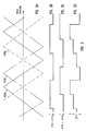
- Fig. 3A represents the PESP and PESQ signals output by demodulator 44 as a function of radial position of servo head 32.
- Figs. 3B and 3C are the digital values of the two comparisons of PESP(n) to +/- PESQ(n).
- Fig. 3D is the digital track type signal, t q (n), computed from the logic of Table 1.
- t q (n) and PES(n) are computed by microprocessor 80.
- Table 1 can be implemented in analog hardware and the resulting track type number, t q (n), input to data bus 84.
- PESP and PESQ can be selected through analog switches to generate, according to the logic of Table 1, a PES which is then sent to a single A/D converter.
- demodulator 44 also provides directly to data bus 84 a one-bit digital signal, GBOD, to indicate that servo head 32 is located over the "guard band outside diameter", i.e. the radially outermost head position in the disk file.
- This signal is generated from a special code recorded on the radially outermost track on servo surface 22.
- IPA 58 provides the analog control current, i(t), to VCM 40 and as feedback to A/D converter 90.
- A/D converter 90 provides to data bus 84 a digital current sample, i(n), corresponding to the sample of analog current, i(t).
- the data inputs to microprocessor 80 of the digital servo control system for purposes of this explanation are control unit commands for target track t d and re-zero RZ, head position relative to nearest track centreline PES(n), which is determined from PESP(n) and PESQ(n) according to Table 1, VCM control current i(n), and GBOD.
- a digital control signal, u(n), is output by microprocessor 80 to a digital-to-analog converter (DAC) 92.
- DAC digital-to-analog converter
- A/D converters 88, 89, 90 are driven by the same clock input so that the digital sampling of PESP, PESQ and i, all occur simultaneously.
- the output of the control signal u(n) computed from the digital sample of PESP(n), PESQ(n) and i(n) occurs after a fixed calculation delay time and before the input of the next digital sample of PESP(n+1), PESQ(n+1) and i(n+1).
- DAC 92 provides the analog control signal, u(t), to IPA 58.
- Microprocessor 80 also sends a special inhibit signal to IPA 58.
- IPA 58 is inhibited when the servo control system is first turned on to prevent any initial signal conditions from causing undesired movement of VCM 40.
- Fig. 2 The simplified block diagram of Fig. 2 is intended only to represent possible hardware implementation of the digital servo control system.
- An important feature of the digital servo control system which is not shown in Fig. 2, but which will be explained below, is the manner in which the microprocessor 80 computes the control signal u(n) so as to eliminate the necessity of a stiffness integrator and the adverse effects of a feedback path around the IPA 58 which has a gain in the presence of bias forces.
- the microprocessor 80 uses an algorithm, referred to as a state estimator, to estimate absolute head position x e , head velocity v e , and head acceleration a e .
- the estimated head position, velocity and acceleration for each digital sample n are functions of the predicted head position, velocity and acceleration, the measured head position and the measured VCM current.
- the predicted head position, velocity and acceleration are updated with each sample and are derived from functions based upon a physical model of the VCM and arm assembly.
- Fig. 4 The operation of the digital servo control system, and in particular the state estimator, will be explained with reference to the graphical representation of Fig. 4. It should be noted that the items in the non-analog portions of Fig. 4, such as the summing junctions, are not discrete hardware components but merely graphical aids to assist in understanding the computations performed by microprocessor 80.
- the state estimator 100 generates outputs of x e (n), v e (n) and a e (n).
- the difference between the target track t d from control unit 86 (Fig. 2) and the estimated head position x e (n) is the "distance-to-go", x tg (n), which is represented as the output of summing junction 101 and is input to VTG 102.
- the input signal representing x tg (n) is operated on in digital VTG 102 to form an output address which is then input to a lookup table stored in PROM 83.
- the output from PROM 83 is a digitised value for the velocity curve which is used directly as a digital velocity command output, V c (n), from VTG 102.
- V c (n) a digital velocity command output
- VTG 102 may utilise a digital curve implementation, as shown in Fig. 1C of US -A- 4,486,797.
- the output of VTG 102 is a velocity command, v c (n), which is a function of the distance-to-go, x tg (n).
- v c (n) is essentially a linear function of the input, x tg (n), and can be represented as k1x tg (n), where k1 is a constant.
- the output v c (n) of VTG 102 is a signal representative of the optimum velocity of the head for the particular sample n and distance to the target x tg (n). This value is then compared, as shown by summing junction 104, with the estimated velocity v e (n) generated by state estimator 100. The difference between v c (n) and v e (n) is the velocity error signal, v es (n), from summing junction 104.
- switch 103 for switching VTG 102 out of the servo control system.
- switch 103 When switch 103 is "switched on” microprocessor 80 provides a constant velocity, v coast , to summing junction 104.
- Switch 103 is switched on and the constant velocity input v coast is provided during initialisation of the servo control system in order to cause the servo head 32 to "coast” at constant velocity from the inside diameter to the guard band outside diameter.
- v es (n) from summing junction 104 is the difference between v coast and the estimated head velocity v e (n).
- v es (n) from summing junction 104 is operated on by a lead-lag algorithm, which is represented graphically as a lead-lag network 106, and then input to summing junction 110.
- state estimator 100 As shown between state estimator 100 and summing junction 108, the estimated head acceleration, a e (n), from state estimator 100 is multiplied by a constant scale factor k2, and the prior control signal u(n-1) is multiplied by a constant scale factor k3. These two products are then summed, as shown by summing junction 108, and the sum subtracted from the output of lead-lag network 106, as shown by summing junction 110. The result is the digital control signal, u(n), which is input to DAC 92.
- switch 111 Located between summing junction 110 and DAC 92 is a switch 111 for switching the normal control signal out of the servo control system.
- switch 111 When switch 111 is "switched on", microprocessor 80 provides a control signal to DAC 92 which is equal to i(n) - i park , where i park is a constant current level.
- the purpose of switch 111 is to "park” the actuator by moving VCM 40 up against the inside diameter crash stop of the disk file. When the actuator is parked, servo head 32 is located over the radially innermost track.
- Equation (1) The last two terms in equation (1) are the output from lead-lag network 106 and are strictly a function of constant scale factors, k si , and the present and prior velocity error signals, v es (n) and v es (n-1), respectively.
- the inhibit signal to IPA 58 is on, thus preventing any initial signal conditions to IPA 58 from causing movement of VCM 40.
- the servo control system then undergoes a "re-zero" routine and receives the re-zero command, RZ, from control unit 86.
- the servo control system's initial function is to park the actuator.
- the park phase is commenced by turning on switch 111. This prevents the otherwise normal control signal from reaching DAC 92.
- the control signal to DAC 92 is now equal to the current to VCM 40 less a constant value, i park .
- the current to VCM 40 will increase until it reaches the value i park .
- VCM 40 will accelerate until it reaches the crash stop and will be maintained at the crash stop as long as switch 111 is on.
- the park phase continues for a predetermined time delay which is sufficient to assure that VCM 40 has been parked.
- the state estimator 100 initialises the estimated values by setting x e equal to x max , the largest possible absolute head position, and v e and a e to zero. Switch 111 is then turned off, so that the normal control signal u(n) is provided to DAC 92.
- the servo control system commences the coast phase, the purpose of which is to move VCM 40 from the inside diameter crash stop to the radially outermost track, i.e. the guard band outside diameter. This is commenced by turning switch 103 on to switch VTG 102 out of the servo control system.
- n is set equal to zero and the sampling of PESP(n) and PESQ(n) begins.
- GBOD is also input to microprocessor 80 and has an initial value of zero. The coast phase continues so long as both switch 103 is on and GBOD equals zero, indicating that servo head 32 has not yet reached the guard band outside diameter.
- microprocessor 80 computes the absolute head position, x a , relative to some fixed reference, such as track zero, which is typically the guard band outside diameter.
- x a (n) is computed according to the following equations (3) and (4).
- x m (n) TW ⁇ t q (n) + PES(n) (3)
- x a (n) J(4TW) + x m (n) (4)
- PES(n) is the distance of the head from the nearest track centreline and is computed from the logic of Table 1.
- the term "TW . t q (n)” is the "track width” times the digital value corresponding to the track type.
- x m (n) is the measured position of the head within some four-track band of the quadrature pattern.
- x a (n) i.e. the measured absolute position of the head relative to a fixed reference, is equal to x m (n) plus some integral multiple, denoted "J", times the width of a four-track band (4TW). In the operation of the servo control system, only x m (n) is actually measured.
- J(4TW) is determined based upon the predicted absolute position of the head from an expression for x p (n) to be described later. This is possible because the state estimator is designed such that the error between the measured absolute head position, x a , and the predicted absolute head position, x p , is always less than two track widths.
- x a is computed by determining J, which is the number of integral multiples of four-track bands, in the predicted absolute head position x p .
- the predicted position x p can be considered as a distance equal to some integral multiple J of four-track bands plus a remainder or fraction of a four-track band). In this manner the term J is used to compute x a in equation (4).
- e(n) x a (n) - x p (n) (5)
- e(n) is the error between the measured absolute head position, x a (n), and the predicted absolute head position, x p (n), for that sample.
- x e (n) x p (n) - L1 ⁇ e(n) (6)
- v e (n) v p (n) - L2 ⁇ e(n) (7)
- w e (n) w p (n) - L3 ⁇ e(n) (8)
- x p (n) in equation (6), v p (n) in equation (7), and w p (n) in equation (8) are the predicted position, velocity and bias force equivalent VCM current, respectively. These terms have been computed during the prediction update phase from the prior sample, and will be explained with reference to that portion of the flow chart of Fig. 5.
- w e (n) in equation (8) is the estimated bias force component of the total VCM current required to give the estimated acceleration of servo head 32.
- the L i terms in equations (6)-(8) are constants.
- the measured VCM current sample, i is input to microprocessor 80.
- a decision is made as to whether the servo control system is still in coast, i.e. whether the head is still moving from the inside diameter crash stop towards the guard band outside diameter. If switch 103 is still on, then the coast phase is still in progress, the commanded velocity, v c , is set equal to v coast , and VTG 102 is bypassed.
- the velocity error signal from equation (9) is the difference between the commanded velocity, in this case v coast , and the estimated velocity, v e (n).
- the estimated acceleration a e (n) in equation (10) is proportional to the sum of the measured VCM current i(n) and the term w e (n), the estimated bias force equivalent current.
- the term w e (n) is an estimate of the VCM current required to compensate for bias forces.
- the proportional constant K f /M in equation (10) is the actuator force constant divided by the actuator mass.
- control signal u(n) is computed according to equation (1) and output to DAC 92.
- the microprocessor 80 next computes the term d s1 (n) from equation (2) and the predicted head position x p (n), velocity v p (n) and bias force equivalent current w p (n) from the following equations (11)-(13).
- x p (n) x e (n-1) + g11 ⁇ u(n-2) + g21 ⁇ u(n-1) + g31 ⁇ i(n-1) + p12 ⁇ v e (n-1) + p13 ⁇ w e (n-1) (11)
- v p (n) v e (n-1) + g12 ⁇ u(n-2) + g22 ⁇ u(n-1) + g32 ⁇ i(n-1) + p23 ⁇ w e (n-1) (12)
- W p (n) w e (n-1) (13)
- the predicted terms x p (n), v p (n) and w p (n) are functions of prior control signals, the prior measured VCM current and the prior estimated head position, velocity and bias force equivalent current.
- the counter is then incremented by one, to n+1. If there is no change in the target track, then control is returned for receipt of the next PESP(n) and PESQ(n) input.
- the above-described routine for the computation of the control signal u during the coast phase continues so long as GBOD equals zero.
- GBOD the guard band outside diameter
- GBOD the absolute position of the guard band outside diameter
- the estimated velocity v e is set equal to v coast
- the estimated acceleration a e is set equal to zero.
- the target track t d is then set equal to x GBOD .
- the coast phase is terminated by "switching off" switch 103.
- the same computations as previously described occur with the exception that when the second decision point for switch 103 is reached, the distance-to-go, x tg , and new commanded velocity, v e , are computed according to the following equations (14) and (15).
- x tg (n) t d - x e (n) (14)
- v c (n) F[x tg (n)] (15)
- the total error signal, x tg computed according to equation (14) is merely the difference between the absolute position of the target track centreline and the estimated absolute head position.
- the function term in equation (15) represents the output from VTG 102 and is a nonlinear function of x tg (n) during track seeking and a linear function, k1x tg (n), during track following.
- the control signal u continues to be calculated according to equation (1) for each sample and output to DAC 92. The seek continues and the counter is incremented to n+1 until a new target track command, t d , is received.
- the g ij and p ij in equations (11)-(13) are constants determined from a physical model of the actuator, including such parameters as the mass of the coil and arm assembly, the frictional effects, the force constants, and the digital sampling time.
- a description of the manner in which the g ij and p ij constants are generated for a physical system is given by Franklin and Powell in Digital Control of Dynamic Systems , Addison-Wesley Publishing Co. (1983), Chapter 6, pp. 131-139.
- the k si , L i , and k i constants are selected constants which yield the desired overall servo control system requirements for servo bandwidth, closed-loop pole locations and transient response.
- the specific values of these constants are a direct function of system design objectives and the specific hardware to be controlled.
- the control signal represented by equation (1) is a function of the prior control signal; the velocity error signal, which in turn is a function of the estimated head velocity and the total error signal; and the estimated head acceleration, which in turn is a function of the measured VCM current and the estimated bias force equivalent VCM current.
- the mean or expected value of absolute head position x e is a constant and the mean or expected value of the head velocity v e is zero.
- the state estimator estimates the bias force equivalent VCM current, w e , so that the total acceleration estimate, which is (K f /M) . [i(n) + w e (n)], has a mean or expected value of zero. In this manner the only term remaining in equation (16) which has a non-zero mean or expected value is the total error signal, x tg , which during track following is simply the PES.
- the PES is driven to zero by IPA 58 without the need for a separate switchable stiffness integrator. With the use of the state estimator in the digital servo control system as described herein to estimate w e , there is thus no feedback path around IPA 58 that provides a gain in the presence of generally constant or very low frequency bias forces.
- the use of the state estimator eliminates the necessity for counting or otherwise estimating track crossings, and thus permits the servo control system to be fully operable with sector servo information.
- the state estimator is designed, through the selection of constants L1, L2 and L3 in equations (6)-(8), so that the measured absolute head position, x a (n), is always within less than two track widths of the predicted head position, x p (n).
- L1, L2 and L3 in equations (6)-(8)
- Curve A of Fig. 6 illustrates an arrival trajectory of head 32 to the centreline of a target track for a typical multiple track seek.
- the discontinuity at approximately 6.0 ms. is caused by the switching of a stiffness integrator into the servo feedback loop.
- the arrival trajectory of Curve A was simulated by the use of a digital servo control system identical to that shown in Fig. 4 but in which a digital stiffness integrator (not shown) was located between summing junction 101 and VTG 102.
- This stiffness integrator was switched into the loop to drive x tg to zero when the servo head 32 was within approximately one-half track of the centreline of the target track.
- the trajectory of Curve B in Fig. 6 shows a smooth, continuous arrival of servo head 32 to the centreline of the target track. This arrival was reached with a digital servo control system embodying the present invention, i.e. without a switchable stiffness integrator.
- Fig. 7 there is illustrated a modification to the above-described digital servo control system which compensates for an offset input voltage to IPA 58.
- Even in the presence of no input to DAC 92 there can be an output voltage offset on DAC 92 and an input voltage offset to IPA 58.
- the value of this offset can vary with time and temperature.
- the control current u(n) is digitally integrated by digital integrator 120. This results in a correction factor b(n) summed with the control signal u(n) to compensate for an input signal offset to IPA 58.
- c0 a non-zero positive constant.
- the microprocessor sets c0(n) equal to zero.
- the use of integrator 120 by setting c0(n) equal to a non-zero value, causes no adverse effects because the variation in the value of b is extremely slow relative to any bias force variations which can occur over the time it takes to do any track seek.
Landscapes
- Moving Of The Head To Find And Align With The Track (AREA)
- Moving Of Head For Track Selection And Changing (AREA)
- Control Of Position Or Direction (AREA)
Claims (14)
- Procédé pour commander la recherche et le suivi de pistes de données dans une unité de disque comportant un disque (12) avec des informations d'asservissement sur celui-ci définissant des centres de pistes de données, une tête (32) pour lire des échantillons des informations d'asservissement pendant la rotation du disque, un mécanisme de positionnement (40) connecté à la tête et sensible à un signal d'entrée pour positionner la tête au centre d'une piste cible pendant la recherche de piste et maintenir la tête sur le centre de la piste cible pendant le suivi de piste, le procédé comprenant les étapes consistant à :
produire à partir des informations d'asservissement un signal d'erreur de position de tête échantillonné (PES) représentatif de la position de la tête par rapport au centre de la piste la plus proche ;
pour chaque échantillon du signal d'erreur de position :
calculer une position absolue mesurée de la tête (xa(n)), par rapport à une référence fixe, à partir du signal d'erreur de position de tête échantillonné (PES) et d'une position de tête absolue prédite précédente (xp(n)) et calculer un signal d'erreur (e(n)) basé sur la différence entre ladite position absolue mesurée de la tête (xa(n)) et ladite position absolue prédite précédente de la tête (xp(n)) ;
mesurer le signal d'entrée (i(n)) vers le mécanisme de positionnement ;
estimer la position absolue de la tête (xe(n)), par rapport à la référence fixe et la vitesse de la tête (ve(n)), en utilisant ledit signal d'erreur (e(n)), ladite position absolue prédite précédente de la tête (xp(n)) et une vitesse prédite précédente (vp(n)) ; estimer le signal d'entrée du mécanisme de positionnement équivalent (we(n)) requis pour compenser les forces de sollicitation agissant sur le mécanisme de positionnement, en utilisant un signal d'entrée de mécanisme de positionnement équivalent aux forces de sollicitation prédite précédentes (wp(n)) et estimer l'accélération de la tâte (ae(n)) comme une fonction du signal d'entrée de mécanisme de positionnement mesure (i(n)) et du signal d'entrée de mécanisme de positionnement équivalent à des forces de sollicitation estimées (we(n)) ;
calculer une vitesse de tête ordonnée (vc(n)) comme une fonction de la distance (xtg(n)) à partir de la position absolue estimée de la tête (xe(n)) à la piste cible (td) et calculer l'erreur de vitesse de la tête (ves(n)) comme une fonction de la différence entre la vitesse de la tête ordonnée (vc(n)) et la vitesse de la tête estimée (ve(n)) ;
prédire en utilisant un estimateur d'état, pour l'échantillon ultérieur du signal d'erreur de position, la position absolue de la tête (xp(n+1)) et la vitesse de la tête (vp(n+1)) comme des fonctions des signaux de commande précédents (u(n), u(n-1)), de la position de la tête absolue estimée précédente (xe(n)), de la vitesse de la tête estimée précédente (ve(n)), du signal d'entrée du mécanisme de positionnement estimé précédent équivalent aux forces de sollicitation (we(n)) et des constantes (gij, pij) représentatives des paramètres physiques du mécanisme de positionnement et également prédire le signal d'entrée du mécanisme de positionnement de forces de sollicitation (wp(n+1)) comme une fonction du signal d'entrée estimé précédent du mécanisme de positionnement de forces de sollicitation (wp(n)) ;
produire un signal de commande (u(n)) comme une fonction de l'erreur de vitesse de la tête (ves(n)), de l'accélération de la tête estimée (ae(n)) et du signal de commande (u(n-1)) produit pour l'échantillon précédent du signal d'erreur de position ;
et mémoriser les valeurs numériques représentatives des signaux de commande (u(n), u(n-1)), du signal d'entrée du mécanisme de positionnement mesuré (i(n)), de la position de la tête estimée (xe(n)), de la vitesse de la tête estimée (ve(n)), du signal d'entrée du mécanisme de positionnement estimé équivalent aux forces de sollicitation (we(n)) et des constantes (gij, pij) représentant des paramètres physiques prédéterminés du mécanisme de positionnement ;
et intégrer le signal de commande (u(n)) pour délivrer le signal d'entrée (i(t)) vers mécanisme de positionnement. - Procédé selon a revendication 1, dans lequel les informations d'asservissement sont du type délivrant un signal principal et un signal en quadrature à partir d'une confiruration en quadrature enregistrée dans des bandes radialement répétitives à quatre pistes, chaque piste dans la bande étant un type de piste particulier et dans lequel l'étape pour produire le signal d'erreur de position comporte l'étape pour déterminer à partir des signaux principal et en quadrature sur lequel des quatre types de piste la tête se trouve.
- Procédé selon la revendication 2, dans lequel l'unité de disque comporte un démodulateur qui délivre un signal d'erreur de position principal et un signal d'erreur de position en quadrature analogique à partir des informations d'asservissement de configuration en quadrature et dans lequel l'étape pour produire un échantillon du signal d'erreur de position comporte les étapes consistant à produire un échantillon du signal d'erreur de position numérique principal (PESP) et un échantillon du signal d'erreur de position numérique en quadrature (PESQ) et sélectionné soit PESP soit PESQ comme échantillon du signal d'erreur de position.
- Procédé selon la revendication 2 ou 3, dans lequel l'étape consistant à mesurer la position de la tête à l'intérieur d'une bande comporte les étapes consistant à identifier le numéro de la piste spécifique sur laquelle la tête se trouve à l'intérieur de la bande, multiplier le numéro de la piste identifiée par la largeur de la piste (TW) et sommer le produit obtenu avec le signal d'erreur de position (xm(n)).
- Procédé selon l'une quelconque des revendications précédentes, dans lequel les informations d'asservissement sont enregistrées dans des bandes radialement répétitives, chaque bande contenant un nombre fixe de pistes particulièrement identifiables et dans lequel l'état consistant à estimer la position de la tête absolue comporte l'étape consistant à mesurer la position de la tête à l'intérieur d'une bande sans détecter ou estimer les croisements de pistes par la tête.
- Procédé selon la revendication 5, dans lequel l'étape d'estimation de la position absolue de la tête comprend de plus l'étape de la détermination d'une distance équivalente au nombre intégral J de bandes constituée par la position absolue prédite de la tête et la sommation de cette distance avec la position de la tête mesurée à l'intérieur d'une bande, le calcul de ce fait d'une position de tête absolue mesurée (xa(n)).
- Procédé selon l'une quelconque des revendications précédentes, dans lequel le mécanisme de positionnement est un moteur à bobine mobile (mbm(40)), dans lequel l'étape consistant à mesurer le signal d'entrée du mécanisme de positionnement comprend par suite l'étape consistant à mesurer le courant d'entrée (i(n)) vers le moteur de la bobine mobile, et dans lequel l'étape consistant à estimer la force de sollicitation équivalente au signal d'entrée du mécanisme de positionnement comprend de plus l'étape consistant à estimer le courant équivalent du moteur de la bobine mobile pour compenser les forces de sollicitation.
- Procédé selon l'une quelconque des revendications précédentes, dans lequel l'étape consistant à estimer l'accélération de la tête comprend de plus l'étape consistant à estimer l'accélération de la tête pour avoir une valeur moyenne nulle lorsque la valeur attendue de la position de la tête est une constante.
- Procédé selon l'une quelconque des revendications précédentes, dans lequel l'unité de disque est du type comportant également un moyen d'intégration (58) couplé au mécanisme de positionnement et comprend de plus les opérations consistant à, avant d'intégrer le signal de commande, ajouter au signal de commande un signal de correction pour corriger un courant résiduel d'entrée du moyen d'intégration et actualiser le signal de correction pendant le suivi de piste.
- Unité de disque comportant un disque (12) avec des informations d'asservissement sur celui-ci définissant des lignes centrales de pistes de données, comprenant une tête (32) pour lire les informations d'asservissement pendant la rotation du disque et pour délivrer un signal d'asservissement analogique ; un mécanisme de positionnement (40) connecté à la tête et sensible à un signal d'entrée pour positionner la tête sur la ligne centrale d'une piste cible en réponse à un ordre de recherche provenant de l'unité de commande (86) et pour maintenir la tête sur la ligne centrale de la piste cible pendant le suivi de piste, le mécanisme de positionnement ayant des paramètres prédéterminés (gij, pij) et étant soumis à des forces de sollicitation généralement constantes ou à basse fréquence pendant le fonctionnement de l'unité de disque et un démodulateur (44) pour traiter le signal d'asservissement analogique pour délivrer un signal d'erreur de positionnement de tête (PES) représentatif de la distance de la tête au centre de ligne de la piste la plus proche et un moyen de conversion analogique/numérique (88, 89) pour convertir le signal d'erreur de positionnement analogique provenant du démodulateur et comprend de plus :
un moyen (80) pour calculer pour chaque échantillon de signal d'erreur de positionnement une position de tête absolue mesurée (xa(n)) par rapport à une référence fixe, à partir du signal d'erreur de positionnement numérique et une position de tête absolue prédite précédemment (xp(n)) et pour calculer un signal d'erreur (a(n)) basé sur la différence entre ladite position de tête absolue mesurée (xa(n)) et ladite position de tête absolue prédite précédente (xp(n)) ;
un moyen pour mesurer le signal d'entrée analogique du mécanisme de positionnement (i(t)) et un moyen de conversion analogique/numérique (90) pour délivrer un signal d'entrée mesuré du mécanisme de positionnement (i(n)) ;
un moyen pour estimer la position absolue de la tête (xe(n)) par rapport à la référence fixe et à la vitesse de la tête (ve(n)), en utilisant ledit signal d'erreur (e(n)), ladite position de tête absolue prédite précédente (xp(n)) et une vitesse prédite précédente (vp(n)) ; un moyen pour estimer le signal d'entrée équivalent du mécanisme de positionnement (we(n)) requis pour compenser lesdites forces de sollicitation agissant sur le mécanisme de positionnement, en utilisant une force de sollicitation prédite précédente équivalente au signal d'entrée du mécanisme de positionnement (wp(n)) et un moyen (80, 108) pour estimer l'accélération de la tête (ae(n)) comme une fonction du signal d'entrée mesuré du mécanisme de positionnement (i(n)) et un signal d'entrée équivalent des forces de sollicitation estimées du mécanisme de positionnement (we(n)) ;
un générateur de trajectoire de vitesse (102) pour calculer une vitesse de tête ordonnée optimale (vc(n)) comme une fonction de la distance (xtg(n)) à partir de la position de la tête absolue estimée (xe(n)) à la piste cible (td) et un moyen (104) pour calculer l'erreur de vitesse de la tête (ves(n)) comme une fonction de la différence entre la vitesse ordonnée de la tête (vc(n)) et de la vitesse estimée de la tête (ve(n)) ;
un estimateur d'état (80) pour prédire pour l'échantillon de signal d'erreur de positionnement suivant, la position absolue de la tête (xp(n+1)) et la vitesse de la tête (vp(n+1) comme des fonctions des signaux de commande précédents (u(n), u(n-1)), de la position de tête absolue estimée précédente (xe(n)), de la vitesse de la tête estimée précédente (ve(n)), du signal d'entrée équivalent des forces de sollicitation estimées précédentes du mécanisme de positionnement (we(n)) et desdites constantes (gij, pij) représentatives des paramètres physiques du mécanisme de positionnement et pour prédire le signal d'entrée équivalent des forces de sollicitation du mécanisme de positionnement (xp(n+1)) comme une fonction du signal d'entrée équivalent des forces de sollicitation estimées précédentes du mécanisme de positionnement (wv(n)) ;
un moyen (106) pour calculer un signal de commande (u(n)) comme une fonction de l'erreur de vitesse de la tête (ves(n)), de l'accélération estimée de la tête (ae(n)) et du signal de commande (u(n-1)) produit par l'échantillon précédent du signal d'erreur de positionnement ;
un moyen pour mémoriser les valeurs numériques représentatives des signaux de commande (u(n), u(n-1)), du signal d'entrée mesuré du mécanisme de positionnement (i(n)), de la position de tête estimée (xe(n)), de la vitesse de la tête estimée (ve(n)), du signal d'entrée équivalent des forces de sollicitation estimées du mécanisme de positionnement (we(n)) et desdites constantes (kij, pij) représentant les paramètres physiques prédéterminés du mécanisme de positionnement, et
un moyen (92) pour convertir le signal de commande numérique (u(n)) en un signal d'entrée analogique destiné au mécanisme de positionnement (i(t)). - Unité de disque selon la revendication 10, dans laquelle les informations d'asservissement sont enregistrées en bandes répétitives radialement d'un nombre fixe de pistes par bande et dans laquelle le démodulateur délivre un signal d'asservissement analogique en quadrature, dans lequel le moyen de conversion analogique/numérique pour le signal d'erreur de position reçu depuis le démodulateur comporte un moyen pour produire un signal d'erreur de position principalement numérique (PESP) et un signal d'erreur de position en quadrature numérique (PESQ) et comprend de plus un moyen pour identifier à partir des signaux d'erreur de position principalement numériques et en quadrature la piste spécifique à l'intérieur d'une bande sur laquelle la tête est placée.
- Unité de disque selon la revendication 10 ou la revendication 11, dans laquelle le moyen pour calculer une estimation de l'accélération de la tête comporte un moyen pour estimer l'accélération moyenne de la tête pendant le suivi de piste pour qu'elle soit égale à zéro.
- Unité de disque selon l'une quelconque des revendications 10 à 12, dans laquelle le moyen pour convertir le signal de commande numérique en un signal analogique de mécanisme de positionnement comporte un amplificateur de puissance intégrateur (58).
- Unité de disque selon la revendication 13, comprenant de plus un moyen pour calculer une valeur représentative d'un signal de correction comme compensation pour un courant résiduel d'entrée vers un amplificateur de puissance intégrateur, un moyen pour ajouter la valeur du signal de correction au signal de commande numérique avant conversion du signal numérique en analogique et un moyen pour mettre à jour la valeur du signal de correction pendant le suivi de piste.
Applications Claiming Priority (3)
| Application Number | Priority Date | Filing Date | Title |
|---|---|---|---|
| US06/857,263 US4679103A (en) | 1986-04-29 | 1986-04-29 | Digital servo control system for a data recording disk file |
| US857263 | 1986-04-29 | ||
| SG147694A SG147694G (en) | 1986-04-29 | 1994-10-13 | A servo control system for a data recording disk file |
Publications (3)
| Publication Number | Publication Date |
|---|---|
| EP0243821A2 EP0243821A2 (fr) | 1987-11-04 |
| EP0243821A3 EP0243821A3 (en) | 1989-02-08 |
| EP0243821B1 true EP0243821B1 (fr) | 1992-11-04 |
Family
ID=26664416
Family Applications (1)
| Application Number | Title | Priority Date | Filing Date |
|---|---|---|---|
| EP87105701A Expired - Lifetime EP0243821B1 (fr) | 1986-04-29 | 1987-04-16 | Système d'asservissement pour disque d'enregistrement de données |
Country Status (7)
| Country | Link |
|---|---|
| US (1) | US4679103A (fr) |
| EP (1) | EP0243821B1 (fr) |
| JP (1) | JP2589689B2 (fr) |
| CA (1) | CA1268857A (fr) |
| DE (1) | DE3782448T2 (fr) |
| HK (1) | HK138694A (fr) |
| SG (1) | SG147694G (fr) |
Families Citing this family (112)
| Publication number | Priority date | Publication date | Assignee | Title |
|---|---|---|---|---|
| US4775903A (en) * | 1986-10-14 | 1988-10-04 | Hewlett-Packard Company | Sampled servo seek and track follow system for a magnetic disc drive |
| US4879612A (en) * | 1986-11-26 | 1989-11-07 | Data Technology Corporation | Head positioning servo-mechanism with error reduction capabilities |
| US4808900A (en) * | 1987-03-02 | 1989-02-28 | Unisys Corp. | Bi-directional difference counter |
| JPS6443879A (en) * | 1987-08-06 | 1989-02-16 | Ibm | Method and apparatus for control of positioning of head |
| US4835633A (en) * | 1987-09-16 | 1989-05-30 | International Business Machines Corporation | Disk file digital servo control system with compensation for variation in actuator acceleration factor |
| US4835632A (en) * | 1987-09-16 | 1989-05-30 | International Business Machines Corporation | Disk file digital servo control system with multiple sampling rate |
| US4816941A (en) * | 1987-09-16 | 1989-03-28 | International Business Machines Corporation | Disk file digital servo control system with optimized sampling rate |
| US4920462A (en) * | 1988-03-07 | 1990-04-24 | Syquest Technology | Disc drive fine servo velocity control and method for head positioning relative to a disc |
| JPH0757111B2 (ja) * | 1988-05-13 | 1995-06-14 | 富士通株式会社 | 磁気ディスクのサーボ回路 |
| US5065263A (en) * | 1988-05-20 | 1991-11-12 | Matsushita Electric Industrial Co., Ltd. | Track following transducer position control system for a disk storage drive system |
| US5001579A (en) * | 1988-05-27 | 1991-03-19 | Eastman Kodak Company | Method and apparatus for centering a transducer over a recorded track on a rotary storage medium |
| US5034746A (en) * | 1988-09-21 | 1991-07-23 | International Business Machines Corporation | Analog-to-digital converter for computer disk file servo position error signal |
| US4914644A (en) * | 1988-09-26 | 1990-04-03 | International Business Machines Corporation | Disk file digital servo control system with coil current modeling |
| US5182684A (en) * | 1989-03-08 | 1993-01-26 | International Business Machines Corporation | Estimator positioning system and method |
| JPH02278582A (ja) * | 1989-04-20 | 1990-11-14 | Fujitsu Ltd | 位置制御回路 |
| US5136439A (en) * | 1989-09-29 | 1992-08-04 | Seagate Technology, Inc. | Sectored servo position demodulator system |
| US5117408A (en) * | 1989-09-29 | 1992-05-26 | Seagate Technology, Inc. | Correlation of sectored servo position information |
| JP2657561B2 (ja) * | 1990-02-09 | 1997-09-24 | 富士通株式会社 | 位置決め制御方式 |
| US5072318A (en) * | 1990-02-13 | 1991-12-10 | International Business Machines Corporation | Disk file with adaptive cancellation of nonrepeatable disk runout |
| SG47005A1 (en) * | 1990-06-28 | 1998-03-20 | Mitsubishi Electric Corp | Movable head position controlling device for magnetic recording and reproducing apparatuses |
| US5071030A (en) * | 1990-07-26 | 1991-12-10 | Marcusen Carroll L | Adhesive label separator |
| WO1992005543A1 (fr) * | 1990-09-18 | 1992-04-02 | Ronald James Kadlec | Systeme de servocommande numerique utilise dans des unites de disques |
| US5844744A (en) * | 1990-12-21 | 1998-12-01 | Fujitsu Limited | Head positioning control apparatus of disk drive and method of controlling the same apparatus |
| JP2611049B2 (ja) * | 1991-02-06 | 1997-05-21 | 富士通株式会社 | 追従制御装置の整定監視方式 |
| US5305447A (en) * | 1991-07-31 | 1994-04-19 | Seagate Technology, Inc. | Multi-task operating system for a disc drive |
| US5381282A (en) * | 1991-10-18 | 1995-01-10 | International Business Machines Corporation | Inter-sample switching of servo control in direct access storage devices |
| JP2608223B2 (ja) * | 1992-03-19 | 1997-05-07 | 富士通株式会社 | アクチュエータのトルク補正方法 |
| JP2621125B2 (ja) * | 1992-03-31 | 1997-06-18 | 富士通株式会社 | オントラック判定方法 |
| US5510939A (en) * | 1992-07-16 | 1996-04-23 | Micropolis Corporation | Disk drive with adaptive positioning |
| US5534692A (en) * | 1992-09-14 | 1996-07-09 | Sony Corporation | Method for detecting origin point of position sensor |
| US5444583A (en) * | 1992-09-30 | 1995-08-22 | Quantum Corporation | Disk drive having on-board triggered digital sampling analyzer |
| JP2771929B2 (ja) * | 1992-10-06 | 1998-07-02 | インターナショナル・ビジネス・マシーンズ・コーポレイション | ディジタル・サーボ制御システム |
| JPH06131833A (ja) * | 1992-10-16 | 1994-05-13 | Nec Ibaraki Ltd | 磁気ディスク装置 |
| US5325247A (en) * | 1992-11-12 | 1994-06-28 | Quantum Corporation | Digital multi-rate notch filter for sampled servo digital control system |
| US5377131A (en) * | 1992-12-31 | 1994-12-27 | International Business Machines Corporation | Digital amplitude estimator |
| US5477103A (en) * | 1993-06-04 | 1995-12-19 | Cirrus Logic, Inc. | Sequence, timing and synchronization technique for servo system controller of a computer disk mass storage device |
| US5576910A (en) * | 1993-06-04 | 1996-11-19 | Cirrus Logic, Inc. | Burst comparison and sequential technique for determining servo control in a mass storage disk device |
| US5404253A (en) * | 1993-06-24 | 1995-04-04 | Fujitsu Limited | Estimator-based runout compensation in a disk drive |
| US5384524A (en) * | 1993-09-02 | 1995-01-24 | Cirrus Logic, Inc. | Voice coil motor control circuit and method for servo system control in a computer mass storage device |
| US5459624A (en) * | 1993-10-26 | 1995-10-17 | International Business Machines Corporation | Activator control method and apparatus for positioning a transducer using a phase plane trajectory trough function for a direct access storage device with estimated velocity and position states |
| KR0128040B1 (ko) * | 1993-11-27 | 1998-04-04 | 김광호 | 디스크 기록 매체를 이용하는 데이타 저장장치의 디지탈 서보제어장치 및 방법 |
| US6115205A (en) * | 1994-03-11 | 2000-09-05 | Seagate Technology, Inc. | Method for adapting seeks of a disc drive transducer to the maximum actuator current available to accelerate and decelerate the transducer |
| US5473550A (en) * | 1994-03-21 | 1995-12-05 | Seagate Technology, Inc. | Fast calibration using microsteps |
| US5694265A (en) * | 1994-04-19 | 1997-12-02 | Fujitsu Limited | Disk apparatus for detecting position of head by reading phase servo pattern |
| US5585976A (en) * | 1994-06-22 | 1996-12-17 | Seagate Technology, Inc. | Digital sector servo incorporating repeatable run out tracking |
| US5589749A (en) * | 1994-08-31 | 1996-12-31 | Honeywell Inc. | Closed loop control system and method using back EMF estimator |
| US5615065A (en) * | 1994-10-04 | 1997-03-25 | International Business Machines Corporation | Phase-compensated servo pattern and position error-sensing detector |
| JP2666747B2 (ja) * | 1994-12-14 | 1997-10-22 | 日本電気株式会社 | 磁気ディスク装置の磁気ヘッド位置決め回路 |
| US5677808A (en) * | 1994-12-19 | 1997-10-14 | Conner Peripherals, Inc. | System and method for controlling a seek operation in a disk drive |
| US5576909A (en) * | 1995-02-16 | 1996-11-19 | Ministor Peripherals International Limited | Method for positioning a data transducer head in a rotating disk drive data storage device |
| US5825582A (en) * | 1995-03-07 | 1998-10-20 | Cirrus Logic, Inc. | Sliding mode control of a disk drive actuator for positioning a read/write head over a selected track during seeking and tracking operations |
| US5781365A (en) * | 1995-03-07 | 1998-07-14 | Cirrus Logic, Inc. | Sliding mode control of a magnetoresistive read head for magnetic recording |
| US5847895A (en) * | 1995-03-07 | 1998-12-08 | Cirrus Logic, Inc. | Chatter reduction in sliding mode control of a disk drive actuator |
| KR100277073B1 (ko) * | 1995-07-24 | 2001-01-15 | 윤종용 | 자기 디스크 구동장치에서 자기 헤드의 속도 및 위치 추정기 |
| JP4100706B2 (ja) | 1995-07-26 | 2008-06-11 | シーラス ロジック,インコーポレイテッド | ディスクドライブアクチュエータの滑動モード制御において改良されたチャタリング低減 |
| KR0156861B1 (ko) * | 1995-11-27 | 1998-12-15 | 김광호 | 하드디스크 드라이브에 있어서 서보제어 이득 자동 보상방법 |
| KR100290604B1 (ko) * | 1995-12-30 | 2001-06-01 | 윤종용 | 자기디스크드라이브에 있어서 인텔리전트 트랙피치 조정방법 |
| US5912782A (en) * | 1996-03-27 | 1999-06-15 | International Business Machines Corporation | System and method for adjusting actuator control current for directional torque variance in a disk drive |
| US5825579A (en) * | 1996-04-04 | 1998-10-20 | International Business Machines Corporation | Disk drive servo sensing gain normalization and linearization |
| US5793555A (en) * | 1996-12-13 | 1998-08-11 | International Business Machines Corporation | Seek optimization for disk files with side-by-side head |
| KR100223633B1 (ko) * | 1996-12-31 | 1999-10-15 | 윤종용 | 하드 디스크 드라이브에서 헤드속도 측정을 이용한 안정 기록방법 |
| US5898286A (en) * | 1997-01-13 | 1999-04-27 | International Business Machines Corporation | Digital servo control system for a data recording disk file with improved saturation modelling |
| US5835300A (en) * | 1997-01-30 | 1998-11-10 | Seagate Technology, Inc. | Dynamic compensation of servo burst measurement offsets in a disc drive |
| US5761007A (en) * | 1997-02-05 | 1998-06-02 | International Business Machines Corporation | Disk drive with multiple actuators on a single axis having different inertia characteristics |
| US5978169A (en) * | 1997-09-23 | 1999-11-02 | Seagate Technology, Inc. | Repeated servo runout error compensation in a disc drive |
| US6195220B1 (en) * | 1998-05-21 | 2001-02-27 | Seagate Technology Llc | Method and apparatus utilizing field ratioing demodulation techniques for a null-type servo pattern |
| US6426845B1 (en) * | 1998-05-21 | 2002-07-30 | Seagate Technology Llc | Asynchronous analog demodulator and method for a null-type servo pattern |
| US6243224B1 (en) * | 1998-05-21 | 2001-06-05 | Seagate Technology Llc | Asynchronous digital demodulator and method for a null-type servo pattern |
| US6219198B1 (en) | 1998-07-14 | 2001-04-17 | International Business Machines Corporation | State estimator alteration for odd sample times in a disk drive servo control system |
| US6344942B1 (en) * | 1998-07-16 | 2002-02-05 | International Business Machines Corporation | Method and apparatus for absolute track spacing determination for self-servowriting |
| KR100493146B1 (ko) * | 1998-07-29 | 2005-09-02 | 삼성전자주식회사 | 멀티레이트추정장치및그방법 |
| US6185467B1 (en) | 1998-09-02 | 2001-02-06 | Cirrus Logic, Inc. | Adaptive discrete-time sliding mode controller |
| US6236895B1 (en) | 1998-09-02 | 2001-05-22 | Cirrus Logic, Inc. | Reference estimator in a discrete-time sliding mode controller |
| US6798611B1 (en) | 1998-09-02 | 2004-09-28 | Cirrus Logic, Inc. | Disk storage system employing a discrete-time sliding mode controller for servo control |
| US6342985B1 (en) | 1998-09-15 | 2002-01-29 | International Business Machines Corporation | Method and apparatus for improving disk drive seek performance |
| JP3295907B2 (ja) * | 1998-11-26 | 2002-06-24 | インターナショナル・ビジネス・マシーンズ・コーポレーション | ヘッドのオフ・トラック・ライト防止方法およびそれを利用した記憶装置 |
| US6570732B1 (en) | 1998-12-15 | 2003-05-27 | Seagate Technology Llc | Method and apparatus for settling determination control systems |
| US6230062B1 (en) | 1999-01-08 | 2001-05-08 | Voyan Technology | Adaptation to unmeasured variables |
| KR20020001742A (ko) | 1999-02-22 | 2002-01-09 | 추후 | 반복 가능한 런아웃 에러 보상 |
| US6490117B1 (en) * | 1999-03-26 | 2002-12-03 | Seagate Technology Llc | Method of thermally printing servo patterns on magnetic media |
| US6377413B1 (en) | 1999-03-26 | 2002-04-23 | Seagate Technology Llc | Method and apparatus for encoding identification information on a magnetic disc |
| JP4365042B2 (ja) | 1999-04-21 | 2009-11-18 | シーゲイト テクノロジー エルエルシー | 自己同調モデル参照式ディスク・ドライブ・コントローラ |
| WO2000068939A1 (fr) | 1999-05-07 | 2000-11-16 | Seagate Technology Llc | Compensation d'erreurs de trajectoire repetees utilisant une commande d'apprentissage iteratif dans un systeme de memoire a disque |
| JP2001006304A (ja) * | 1999-06-23 | 2001-01-12 | Matsushita Electric Ind Co Ltd | 磁気ディスク装置 |
| US6437936B1 (en) | 1999-07-23 | 2002-08-20 | Seagate Technology Llc | Repeatable runout compensation using a learning algorithm with scheduled parameters |
| US6490111B1 (en) | 1999-08-25 | 2002-12-03 | Seagate Technology Llc | Method and apparatus for refreshing servo patterns in a disc drive |
| US6441986B1 (en) | 1999-09-07 | 2002-08-27 | Iomega Corporation | System and method for minimizing write-over encroachment in a disk due to radial sinusoidal runout at the fundamental frequency |
| US6236536B1 (en) | 1999-09-07 | 2001-05-22 | Iomega Corporation | System and method of servo compensation for friction induced off track problem in a data storage device |
| US6952320B1 (en) | 1999-12-16 | 2005-10-04 | Seagate Technology Llc | Virtual tracks for repeatable runout compensation |
| US6671119B2 (en) | 2000-04-18 | 2003-12-30 | Seagate Technology Llc | Method and apparatus to encode position error signal correction information |
| US6751043B2 (en) * | 2000-12-15 | 2004-06-15 | Texas Instruments Incorporated | Digital servo control system for a hard disc drive using a voice coil motor in voltage mode |
| US7177106B2 (en) * | 2001-02-26 | 2007-02-13 | Matsushita Electric Industrial Co., Ltd. | Disk storage apparatus |
| US6831808B2 (en) | 2001-08-15 | 2004-12-14 | Hitachi Global Storage Technologies Netherlands B.V. | Method and apparatus for determining track identity from abbreviated track identifying data in a disk drive data storage device |
| US6775081B2 (en) | 2001-08-15 | 2004-08-10 | Hitachi Global Storage Technologies Netherlands B.V. | Servo format for disk drive data storage devices |
| US6950274B2 (en) * | 2001-11-28 | 2005-09-27 | Matsushita Electric Industrial Co., Ltd. | Disk storage apparatus and disk storage apparatus control method |
| EP1568033A1 (fr) * | 2002-11-27 | 2005-08-31 | Koninklijke Philips Electronics N.V. | Procede permettant a une tete d'exploration d'executer un saut de piste pour recuperer des donnees d'un support |
| KR100475121B1 (ko) * | 2002-12-16 | 2005-03-10 | 삼성전자주식회사 | 디스크 드라이브의 안착 서보 제어 방법 및 장치 그리고이에 적합한 vcm 액튜에이터의 가속도 상수 추정 방법및 이에 적합한 장치들 |
| US7119511B2 (en) * | 2003-04-11 | 2006-10-10 | International Business Machines Corporation | Servo system for a two-dimensional micro-electromechanical system (MEMS)-based scanner and method therefor |
| US7215503B2 (en) * | 2003-06-20 | 2007-05-08 | Seagate Technology Llc | Time linear arrival for velocity mode seeks |
| US6999263B1 (en) * | 2003-10-24 | 2006-02-14 | Western Digital Technologies, Inc. | Method and apparatus for self servowriting of tracks of a disk drive using a servo control loop having a two-dimensional weighted digital state compensator |
| US7667922B1 (en) * | 2004-01-08 | 2010-02-23 | Seagate Technology Llc | Estimation of bias force for data tracking in a disk drive |
| US20060066986A1 (en) * | 2004-09-24 | 2006-03-30 | Teng-Yuan Shih | Seek servomechanism with extended sinusoidal current profile |
| US20060077588A1 (en) * | 2004-10-12 | 2006-04-13 | Teng-Yuan Shih | Generalized sinusoidal trajectory for seek servomechanism of hard drives |
| TWI302233B (en) * | 2005-08-19 | 2008-10-21 | Delta Electronics Inc | Method for estimating load inertia and a system for controlling motor speed by using inverse model |
| CN1925310B (zh) * | 2005-08-30 | 2010-05-12 | 台达电子工业股份有限公司 | 利用逆算模型的马达速度控制系统和负载惯量估测方法 |
| US7782003B2 (en) * | 2005-11-03 | 2010-08-24 | Seagate Technology Llc | Positional indicia misplacement compensation |
| US7676282B2 (en) * | 2005-12-02 | 2010-03-09 | International Business Machines Corporation | Compression of servo control logging entries |
| US7477473B2 (en) * | 2006-01-18 | 2009-01-13 | Maxtor Corporation | Servo positioning adjustment |
| US7549407B2 (en) | 2007-03-28 | 2009-06-23 | Gm Global Technology Operations, Inc. | Method and system for controlling a valve device |
| US7558016B1 (en) | 2007-04-20 | 2009-07-07 | Western Digital Technologies, Inc. | Disk drive servo control techniques for predicting an off-track condition utilizing an estimation filter |
| US7885717B2 (en) * | 2008-03-31 | 2011-02-08 | Sikorsky Aircraft Corporation | Fast control law optimization |
| US8830617B1 (en) * | 2013-05-30 | 2014-09-09 | Western Digital Technologies, Inc. | Disk drive adjusting state estimator to compensate for unreliable servo data |
Family Cites Families (5)
| Publication number | Priority date | Publication date | Assignee | Title |
|---|---|---|---|---|
| GB1583545A (en) * | 1976-08-04 | 1981-01-28 | Martin Sanchez J | Control systems |
| US4184108A (en) * | 1977-11-23 | 1980-01-15 | Sperry Rand Corporation | Self-regulating electronic tachometer |
| US4133011A (en) * | 1977-12-23 | 1979-01-02 | International Business Machines Corporation | Sampled data positioning system employing a model of the physical system for time optimal control |
| US4246536A (en) * | 1978-09-29 | 1981-01-20 | International Business Machines Corporation | Electronic velocity measurement device |
| US4486797A (en) * | 1982-11-22 | 1984-12-04 | International Business Machines Corporation | Sliding mask variable resolution velocity trajectory for track following servo |
-
1986
- 1986-04-29 US US06/857,263 patent/US4679103A/en not_active Expired - Lifetime
-
1987
- 1987-03-13 CA CA000532018A patent/CA1268857A/fr not_active Expired
- 1987-03-26 JP JP62070561A patent/JP2589689B2/ja not_active Expired - Lifetime
- 1987-04-16 DE DE8787105701T patent/DE3782448T2/de not_active Expired - Fee Related
- 1987-04-16 EP EP87105701A patent/EP0243821B1/fr not_active Expired - Lifetime
-
1994
- 1994-10-13 SG SG147694A patent/SG147694G/en unknown
- 1994-12-08 HK HK138694A patent/HK138694A/en not_active IP Right Cessation
Non-Patent Citations (2)
| Title |
|---|
| IBM TECHNICAL DISCLOSURE BULLETIN volume 21, no. 5, October 1978, pages 1792-1795; J.P. MANTEY: "Offset force correction for disk file" * |
| IEEE TRANSACTION ON MAGNETICS volume MAG-17, no. 4, July 1981, pages 1396-1402; C. MAURY: "High track density for magnetic disk drives with an "embedded servo" positioning system * |
Also Published As
| Publication number | Publication date |
|---|---|
| SG147694G (en) | 1995-03-17 |
| HK138694A (en) | 1994-12-16 |
| DE3782448D1 (de) | 1992-12-10 |
| EP0243821A3 (en) | 1989-02-08 |
| CA1268857A (fr) | 1990-05-08 |
| EP0243821A2 (fr) | 1987-11-04 |
| DE3782448T2 (de) | 1993-05-06 |
| JPS62257682A (ja) | 1987-11-10 |
| US4679103A (en) | 1987-07-07 |
| JP2589689B2 (ja) | 1997-03-12 |
Similar Documents
| Publication | Publication Date | Title |
|---|---|---|
| US4679103A (en) | Digital servo control system for a data recording disk file | |
| EP0361786B1 (fr) | Commande d'asservissement numérique pour mémoire à disques | |
| EP0414694B1 (fr) | Systeme et procede de positionnement d'estimateur | |
| EP0442650B1 (fr) | Mémoire à disque avec correction adaptive de l'ovalisation non répétitive du disque | |
| US4835633A (en) | Disk file digital servo control system with compensation for variation in actuator acceleration factor | |
| US4816941A (en) | Disk file digital servo control system with optimized sampling rate | |
| US4616276A (en) | Disk file servo control system with fast reduction of repeatable head position error | |
| US6850385B1 (en) | Repeated servo runout error compensation in a disc drive | |
| EP0003070B1 (fr) | Dispositif digital de positionnement utilisant un modèle du système physique pour un système de commande à temps optimal | |
| US6178060B1 (en) | Current profile shaping to reduce disc drive seek time variation and acoustic noise generation | |
| US5917672A (en) | Disk file head positioning servo system incorporating adaptive saturated seek and head offset compensation | |
| US5898286A (en) | Digital servo control system for a data recording disk file with improved saturation modelling | |
| EP0308070B1 (fr) | Fichier à guide d'enregistrement de données avec commande d'asservissement numérique | |
| US6545838B1 (en) | Self tuning model reference controller in a disc drive | |
| EP0456348A2 (fr) | Méthode et dispositif de commande de la position de la tête dans un dispositif d'emmagasinage de disques | |
| US7215503B2 (en) | Time linear arrival for velocity mode seeks | |
| JPH0330157A (ja) | 磁気デイスク装置の位置制御装置 | |
| Chen et al. | Application of digital servo control on high-performance VCM in HDD | |
| EP0974143A1 (fr) | Appareil et procede de detection de la vitesse du bras de la tete d'une unite de disques pendant le chargement de la tete | |
| JPH01294281A (ja) | 位置決め制御装置 |
Legal Events
| Date | Code | Title | Description |
|---|---|---|---|
| PUAI | Public reference made under article 153(3) epc to a published international application that has entered the european phase |
Free format text: ORIGINAL CODE: 0009012 |
|
| AK | Designated contracting states |
Kind code of ref document: A2 Designated state(s): DE FR GB IT |
|
| 17P | Request for examination filed |
Effective date: 19880224 |
|
| PUAL | Search report despatched |
Free format text: ORIGINAL CODE: 0009013 |
|
| AK | Designated contracting states |
Kind code of ref document: A3 Designated state(s): DE FR GB IT |
|
| 17Q | First examination report despatched |
Effective date: 19901012 |
|
| GRAA | (expected) grant |
Free format text: ORIGINAL CODE: 0009210 |
|
| AK | Designated contracting states |
Kind code of ref document: B1 Designated state(s): DE FR GB IT |
|
| ITF | It: translation for a ep patent filed | ||
| REF | Corresponds to: |
Ref document number: 3782448 Country of ref document: DE Date of ref document: 19921210 |
|
| ET | Fr: translation filed | ||
| PLBE | No opposition filed within time limit |
Free format text: ORIGINAL CODE: 0009261 |
|
| STAA | Information on the status of an ep patent application or granted ep patent |
Free format text: STATUS: NO OPPOSITION FILED WITHIN TIME LIMIT |
|
| 26N | No opposition filed | ||
| PGFP | Annual fee paid to national office [announced via postgrant information from national office to epo] |
Ref country code: FR Payment date: 19960412 Year of fee payment: 10 |
|
| PGFP | Annual fee paid to national office [announced via postgrant information from national office to epo] |
Ref country code: DE Payment date: 19970422 Year of fee payment: 11 |
|
| PG25 | Lapsed in a contracting state [announced via postgrant information from national office to epo] |
Ref country code: FR Free format text: LAPSE BECAUSE OF NON-PAYMENT OF DUE FEES Effective date: 19971231 |
|
| REG | Reference to a national code |
Ref country code: FR Ref legal event code: ST |
|
| PG25 | Lapsed in a contracting state [announced via postgrant information from national office to epo] |
Ref country code: DE Free format text: LAPSE BECAUSE OF NON-PAYMENT OF DUE FEES Effective date: 19990202 |
|
| PGFP | Annual fee paid to national office [announced via postgrant information from national office to epo] |
Ref country code: GB Payment date: 20010409 Year of fee payment: 15 |
|
| REG | Reference to a national code |
Ref country code: GB Ref legal event code: IF02 |
|
| PG25 | Lapsed in a contracting state [announced via postgrant information from national office to epo] |
Ref country code: GB Free format text: LAPSE BECAUSE OF NON-PAYMENT OF DUE FEES Effective date: 20020416 |
|
| GBPC | Gb: european patent ceased through non-payment of renewal fee |
Effective date: 20020416 |
|
| PG25 | Lapsed in a contracting state [announced via postgrant information from national office to epo] |
Ref country code: IT Free format text: LAPSE BECAUSE OF NON-PAYMENT OF DUE FEES;WARNING: LAPSES OF ITALIAN PATENTS WITH EFFECTIVE DATE BEFORE 2007 MAY HAVE OCCURRED AT ANY TIME BEFORE 2007. THE CORRECT EFFECTIVE DATE MAY BE DIFFERENT FROM THE ONE RECORDED. Effective date: 20050416 |