EP0243942A2 - Gouverne hydrodynamique pour bateaux à puissance assistée - Google Patents
Gouverne hydrodynamique pour bateaux à puissance assistée Download PDFInfo
- Publication number
- EP0243942A2 EP0243942A2 EP19870106173 EP87106173A EP0243942A2 EP 0243942 A2 EP0243942 A2 EP 0243942A2 EP 19870106173 EP19870106173 EP 19870106173 EP 87106173 A EP87106173 A EP 87106173A EP 0243942 A2 EP0243942 A2 EP 0243942A2
- Authority
- EP
- European Patent Office
- Prior art keywords
- rudder
- servo
- servo control
- control according
- pendulum
- Prior art date
- Legal status (The legal status is an assumption and is not a legal conclusion. Google has not performed a legal analysis and makes no representation as to the accuracy of the status listed.)
- Withdrawn
Links
Images




Classifications
-
- B—PERFORMING OPERATIONS; TRANSPORTING
- B63—SHIPS OR OTHER WATERBORNE VESSELS; RELATED EQUIPMENT
- B63H—MARINE PROPULSION OR STEERING
- B63H25/00—Steering; Slowing-down otherwise than by use of propulsive elements; Dynamic anchoring, i.e. positioning vessels by means of main or auxiliary propulsive elements
- B63H25/02—Initiating means for steering, for slowing down, otherwise than by use of propulsive elements, or for dynamic anchoring
- B63H25/04—Initiating means for steering, for slowing down, otherwise than by use of propulsive elements, or for dynamic anchoring automatic, e.g. reacting to compass
Definitions
- the invention relates to a hydrodynamic servo control according to the preamble of claim 1.
- the reference variable is either the angular deviation of the wind on a wind vane system set to a desired direction or the angular deviation between a compass heading and an actual compass heading of the boat.
- the actuating force of the actuator is correspondingly provided from the wind power or from the power of an electrically or fluidically operated motor controlled by the command variable.
- the actuating force of the actuator is transmitted via the force transducer to the servo pendulum rudder, which thereby rotates out of its neutral position of its rudder blade extending in the keel direction and out of the keel direction by flowing water with a relatively large force transversely to the keel direction in one of its two swivel directions compared to the force of the actuator is pivoted.
- This force can then be transmitted in many different ways to a rudder with a single rudder shaft arranged transversely to the keel direction in order to generate a course-correct course correction.
- the force transmitter consists of a bevel gear transmission, in which a drive bevel gear is arranged coaxially with the carrier shaft and meshes with an output bevel gear forming the upper end of the rudder shaft.
- Servo pendulum rudder controls of this type are primarily suitable for controlling boats, in particular sailing boats, in open waters. They cannot be used to control the boat in narrow waterways and when maneuvering the boat, such as when mooring and unloading, during locks or similar maneuvers; rather, the servo pendulum rudder submerged in the water interferes with the perfect control of the boat when the servo control is out of operation.
- Another disadvantage of the servo pendulum rudder controls is the risk of the pendulum rudder breaking due to collisions, for example with flotsam, and high dynamic forces when the boat is used hard in extreme seas.
- the object of the invention is to avoid the aforementioned disadvantages in a generic hydrodynamic servo control and to create such a servo control by means of which controllability and maneuvering are possible Availability of the boat provided with the servo control is improved both when the servo control is in operation and when it is not in operation, with the greatest possible operational safety and ship safety, and at the same time a permanent operational readiness of the servo control is made possible.
- This object is achieved with the generic features of claim 1.
- the servo pendulum rudder can be completely removed from the water with a single movement and brought into a position in which it does not protrude laterally beyond the boat dimensions; at most the connection to the rudder must be uncoupled; - The risk of collision and breakage of the servo pendulum rudder when maneuvering in port and lock systems is almost completely prevented because all parts at risk of breakage when the servo pendulum rudder is raised are far above the waterline and thus in the field of vision of the helmsman; - When used on sailboats, which are temporarily controlled by hand, the additional flow resistance of the servo pendulum oar can be easily eliminated - in addition, when driving under motor, any load on the servo pendulum oar is prevented by the strong and often pulsating propeller current; - In all dangerous situations, such as unsettled sails, man-overboard maneuvers etc., a risk of breakage of the servo pendulum
- the force transmitter consists of a bevel gear transmission known per se, in which a drive bevel gear is arranged coaxially with the carrier shaft and meshes with an output bevel gear forming the upper end of the rudder shaft of the servo pendulum rudder.
- the drive bevel gear is rotatably mounted in the end of the carrier shaft facing away from the boat.
- both can also be achieved if the drive bevel gear is arranged on the side opposite the carrier shaft with respect to the driven bevel gear; if the drive bevel gear is supported at the end of the carrier shaft, however, more favorable lever ratios are achieved on the power transmission.
- the use of a bevel gear as a power transmission has the advantage that the servo pendulum rudder is returned to its vertical neutral position seen in the keel direction exactly to the extent that the course of the boat approaches the target course again after a lateral pendulum deflection.
- the actuator When the boat gradually approaches the set course, the actuator returns the drive bevel gear to its neutral position. However, this also rotates the servo pendulum rudder blade - in the opposite direction with respect to the start of the course correction. As a result, the servo pendulum rudder blade flows against the other side and is pivoted back relatively quickly into its vertical neutral position as seen in the keel direction. This prevents oversteer.
- the transmission ratio between the command variable and the angle of attack of the servo pendulum rudder blade can be selected to be less than 1: 1, preferably 1: 2.
- the gear ratio z. B. can be optimized according to the sea conditions by means of length-adjustable levers.
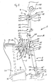
- a hydrodynamic servo control 1 on the mirror 2 of a boat 3 is offset from the center to the left or screwed down in the center by means of a holder 4.
- the bracket 4 consists of a mounting segment 5 which can be screwed onto the mirror 2 with four screws and a bearing 6 which can be screwed to the mounting segment 5 at a freely selectable angle for the fixed mounting of a support shaft 7, around which a servo pendulum rudder 8 transversely to the keel direction K of the boat 3 in the direction the arrows S1 and S2 is pivotally mounted and furthermore carries an actuator 9 or 10 and a force transmitter 11 for rotating the servo pendulum rudder 8.
- the servo pendulum rudder 8 has a bearing segment 12, a rudder shaft 13 and a rudder blade (servo pendulum rudder blade) 14.
- the bearing segment is preferably a light metal casting with two axially spaced bearing bushes 15, 15 ⁇ for the pivoting movement and with axially spaced bearing bushes 16, 16 ⁇ for the rotational movement - according to arrows D1 and D2 - of the servo pendulum rudder 8.
- the bearing segment 12 has a power transmission lever 17 for transmitting the Pivoting movement of the servo pendulum rudder 8 onto the tiller handle 19 of a control rudder 20 by means of cables 18 or a joint / push rod combination 61.
- the bearing bush 16 ⁇ for the rudder shaft 13 is preferably held by an extension tube 21 of the bearing segment 12, it being possible for the extension tube to be formed in one piece with the bearing segment 12 or to be rigidly fixed thereon.
- the rudder shaft 13 is at its upper end with a Ab bevel gear 22 (Fig. 3) rotatably connected and its length at the lower end can be freely adapted to the local conditions of the boat.
- a rudder blade holder 23 is attached, which has laterally spaced, large holding jaws 24, 25 with preferably approximately circular holding surfaces, between which the rudder blade 14 is held by means of a holding bolt 26 and held in position by means of a shear bolt 27.
- a holding arm 28 is fixed between the two bearing bushes 15 and 15 ⁇ of the bearing segment 12 on the support shaft 7 by means of a screw 29.
- the support arm 28 is curved in a side view, ie in a vertical plane parallel to the keel direction K, such that its tubular free end 30 is viewed in a side view essentially above the driven bevel gear 22 of the servo pendulum rudder 8 and viewed in the keel direction so that the support arm 28 is laterally offset Leave space for the servo pendulum rudder 8 swiveled up by about 180 °.
- the holding arm 28 is also curved in a second vertical plane extending transversely to the keel direction K in such a way that the double-curved holding arm surrounds the servo pendulum rudder, which is swiveled up by about 180 °, partially, ie approximately in a quarter circle (see FIG. 1b).
- An elastic element 31 arranged at the free end of the holding arm 28 serves as a stop for the servo pendulum rudder 8 swiveled up by 180 °.
- a wind direction-dependent actuator 9 is connected at the upper end of a support tube 32 rotatably mounted about its axis in the holding arm 28 with the latter.
- a remotely controllable worm gear 33 or the like By means of a remotely controllable worm gear 33 or the like, the support tube 32 and thus the entire actuator 9 can be rotated through at least 360 °, preferably endlessly, in particular continuously, in both directions of the arrow D3.
- a bearing head 34 receives the upper end of the support tube and is rigidly fixed to this end of the support tube by means of a bolt 35.
- a bearing surface 36 of the bearing head 34 which is preferably inclined up to approximately 45 ° with respect to the vertical, supports a balanced wind vane pendulum 39, consisting of a wind vane 40 and a wind vane counterweight pendulum 41, via a central bore 37 and a shaft 38; the latter has, with respect to the shaft 38 (pivot shaft), holding jaws 42 which are shaped and acting in a similar manner on the wind vane side to the holding jaws 24 and 25 on the servo pendulum rudder 8.
- the wind vane counterweight pendulum 41 On the side opposite the shaft 38 of the wind vane, the wind vane counterweight pendulum 41 has a counterweight 43 and a bore 44 through which the wind vane pendulum 39 can be locked in the vertical position by means of a bolt 45.
- the bolt 45 is pushed through the bore 44 and a bore 46 provided vertically below the shaft 38 in the bearing head 34.
- Cams 47 on the periphery of the bearing surface 36 of the bearing head 34 limit the pivoting angle of the wind vane pendulum 39 in cooperation with a bolt 48 protruding from the wind vane counterweight pendulum 41.
- the wind vane counterweight pendulum 41 is at the height of the shaft 38 with a lever arm 49 which can be predetermined in its axial length (see FIG. 5), preferably made of plastic , Mistake.
- a push rod 50 is articulated.
- the push rod 50 extends through the bearing head 34 and the support tube 32 and the free end 30 of the holding arm 28 and, via a lever 51 (FIG. 1 a / b), rotates a drive bevel gear 52 which is rotatably mounted coaxially in the free end of the support shaft 8 of the holder 4.
- the drive bevel gear 52 preferably has half the number of teeth of the driven bevel gear 22 meshing with it at the upper end of the rudder shaft 13 of the servo pendulum rudder 8.
- the length of the lever arm 51 can also be changed for fine adjustment of the yaw angle by changing the position of the point of application of the push rod 50 accordingly.
- a cap-shaped housing 53 made of plastic (FIG. 3) is pushed over the bevel gear transmission consisting of the drive bevel gear 52 and the driven bevel gear 22 and protects it from the weather.
- the servo control works as follows:
- the support tube 32 When the boat 3 is on the desired course, the support tube 32 is rotated about its axis until the wind vane 40 is exactly in the wind direction and consequently perpendicular. In the case shown in FIGS. 1a and 2 (as well as 7a / b), the wind comes exactly from the front.
- the transmission elements for transmitting the pendulum motion of the wind vane pendulum 39 to the servo pendulum rudder 8 are dimensioned such that in this situation the servo pendulum rudder 8 extends parallel to the wind vane pendulum 39 and at the same time the rudder blade 14 of the servo pendulum rudder 8 points in the keel direction K and thus assumes its rest position.
- the rudder 20 which can be the main rudder of the boat 3 (FIGS. 1 a / b and 2) or an emergency or auxiliary rudder (FIGS. 7 a / b), is mentioned with the power transmission lever 17 of the servo pendulum rudder 8 in the introduction Way connected.
- a deviation of the boat 3 from its target course now leads to a transverse component of the air flow on the wind vane 40, as a result of which this is pivoted in the direction of the arrow S3 or S4 (FIG. 1a).
- This pivoting movement is transmitted in the manner described above to the drive bevel gear 52 in the sense of a rotary movement, as a result of which the rudder blade 14 of the servo pendulum rudder 8 rotates in the direction of arrow D1 or D2 and consequently flows with a transverse component from the flowing water and is pivoted sideways in the direction of arrow S2 or S1 from its neutral position.
- This pivoting movement is transmitted in the manner described above to the rudder 20 in such a way that it rotates in the direction of the arrow D5 or D6 and thereby brings the boat 3 back to the desired course.
- a course-dependent actuator 10 in the form of a known, compass-controlled linear motor 54 with a push rod 55 is used, course corrections are carried out in a manner corresponding to the above-described functional sequence.
- a stationary bearing block 56 of the linear motor 54 is preferably captive in a bore 57 of the bearing head 4, preferably secured in connection with the bolts 55 fixing the wind vane pendulum 39.
- the push rod 55 then acts on the correspondingly lengthened lever 51, which rotates the drive bevel gear 52.
- This parallel arrangement of the push rods 50 and 55 for wind-dependent and course-dependent automatic servo control of the boat results in particularly high flexibility of use with particularly simple and safe handling, such as breakage resistance Arrangement reached (Fig. 1a).
- the servo pendulum rudder 8 can be pivoted completely out of the water at any time by means of a care line or the like and can be secured to the support tube 32 in this position. For this purpose, only the connection to the rudder 20 has to be released, while nothing needs to be changed in the connection to the actuator. During this pivoting by 180 °, the servo pendulum rudder 8 rotates according to the transmission ratio of the bevel gear by a certain angle, i. H. in the exemplary embodiment by an angle of 90 ° (according to FIG. 1b).
- a bracket 4 suitable for each rear shape should be stepless be adjustable in angle.
- the fastening segment 5 has elongated holes 5 ⁇ lying on an arc on both laterally spaced semicircular segments 5 ⁇ . Through this grip bolts 6 ⁇ , which can be tightened in the bearing 6 by means of corresponding threads 6 ⁇ .
- the bearing 6 has a bore 7 ⁇ for receiving the support shaft 7, which can be fixed via a bore 7 ⁇ at right angles thereto and a corresponding bolt. By turning the bearing 6 through 180 ° (around the support shaft 7), the adjustment angle range can be increased.
- a through hole 58 arranged perpendicular to the support shaft 7 in the bearing 6 enables a horizontally extending tubular strut 59 or the like to be pushed through at the ends of which deflection blocks 60 for the cable pulls 18 can be located, so that the servo control 1 represents an easily assembled, complete compact unit.
- the pivoting movement of the servo pendulum rudder can also act on a piston / cylinder unit which enables course correction deflections of the control rudder 20 by hydraulic means.
- the servo control can have a self-contained rudder that is totally independent of the boat's rudder, operated by the servo pendulum rudder in a manner similar to the rudder 20 or other hydrodynamic servo controls for boats on the market.
- the servo control according to the invention consists of only a few parts and has a particularly low weight, which can also be reduced further by the buoyancy of the rudder blade 14.
- the servo control is attached to an emergency or auxiliary control rudder 20 attached to the boat stern, to which the power transmission of the servo control takes place.
- Such an arrangement known per se has the advantage in the servo control according to the invention that it can be handled and maneuvered much better than known self-controls even in coastal areas where the self-control is more frequently engaged and disengaged, because the servo pendulum rudder, which is at risk of injury, is simple when not required is folded out of the water by 180 ° so that only lockable and comparatively injury-insensitive emergency and auxiliary control rudders 20 are in the water and the advantages known for such emergency and auxiliary control rudders, such as use as emergency rudder and improvement of the maneuvering properties of the boat maintains.
- the overall depth of the servo control can be kept almost as small as in the exemplary embodiment according to FIGS. 1 to 6 because the support shaft 7 is in one preferably formed as a cast part 6 of the bracket 4 can be inserted laterally next to a support tube 69 and solidly attached, especially since the diameter of the support tube 69 is relatively large, for example Is 100 mm.
- a further reduction in overall depth is possible in that the free power transmission end 62 of the power transmission lever 17 of the servo pendulum rudder 8 is arranged offset to the rear - in the exemplary embodiment in the form of an optically and well-fitting circular segment. As a result, favorable lever ratios are achieved on the tiller handle 19 (FIGS. 7 and 9).
- the tiller handle 19 can be removed from the, preferably square, head 70 of the rudder 20, in particular can be pulled off at the top, the servo pendulum rudder can be uncoupled very quickly and easily from the rudder 20 and, if necessary, an emergency tiller (not shown in the drawing) can be placed on the head 70, whereby a good power transmission is guaranteed.
- a very precise power transmission between the laterally pivoting power transmission lever 17 of the servo rudder 8 and the rudder shaft of the control rudder 20 or its tiller handle 19 is possible by means of a joint / push rod combination 61, the general function and movement geometry of which is shown in principle in FIG. 8.
- the joint / push rod combination 61 according to FIGS. 7 and 9 has proven to be particularly precise, elegant and effective.
- Such a power transmission is also suitable for such generic servo controls in which the servo pendulum rudder can only be pivoted in a comparatively small angular range.
- This power transmission unit also makes it possible to naturally limit the various rudder deflections to specific maximum values without external aids, which is explained below:
- FIGS. 9a to 9c For the sake of simplicity and clarity, instead of some components, only dash-dotted lines representing them are shown in FIGS. 9a to 9c. Likewise, the lines of movement of the spherical centers shown with circles are given for the entire swivel range. From Fig. 9b it can be seen that due to the leverage ratio selected there Nisse and mutual arrangement of the joint balls 63 and 64 of the rudder deflection of the rudder 20 is limited to 40 ° on both sides of the neutral position, with the servo pendulum rudder in the extreme positions of the rudder 20 not more than 30 ° from the neutral vertical position to the side in the special embodiment shown is inclined (Fig. 9c).
- the joint balls 63 and 64 are preferably rigidly attached to the power transmission end 62 of the power transmission lever 17 or at the free end of the tiller handle 19 and are supported with sufficient play and rotation possibilities about all three spatial axes in joint sockets 66 and 67 of the joint / push rod combination 61 of the push rod 65 .
- the assembly and setting of a certain bearing clearance is made possible by the fact that the push rod 65 consists of four socket segments 68 which can be screwed to a central fastening block (not shown in the drawing for reasons of clarity) and can thus be connected to one another.
Landscapes
- Chemical & Material Sciences (AREA)
- Engineering & Computer Science (AREA)
- Combustion & Propulsion (AREA)
- Mechanical Engineering (AREA)
- Ocean & Marine Engineering (AREA)
- Toys (AREA)
Applications Claiming Priority (2)
| Application Number | Priority Date | Filing Date | Title |
|---|---|---|---|
| DE19863614514 DE3614514C2 (de) | 1986-04-29 | 1986-04-29 | Hydrodynamische Servosteuerung für Boote |
| DE3614514 | 1986-04-29 |
Publications (1)
| Publication Number | Publication Date |
|---|---|
| EP0243942A2 true EP0243942A2 (fr) | 1987-11-04 |
Family
ID=6299797
Family Applications (1)
| Application Number | Title | Priority Date | Filing Date |
|---|---|---|---|
| EP19870106173 Withdrawn EP0243942A2 (fr) | 1986-04-29 | 1987-04-28 | Gouverne hydrodynamique pour bateaux à puissance assistée |
Country Status (2)
| Country | Link |
|---|---|
| EP (1) | EP0243942A2 (fr) |
| DE (1) | DE3614514C2 (fr) |
Cited By (3)
| Publication number | Priority date | Publication date | Assignee | Title |
|---|---|---|---|---|
| DE29714603U1 (de) * | 1997-08-18 | 1998-12-17 | Förthmann, Peter, 22041 Hamburg | Selbststeueranlage für Boote |
| EP0897858A3 (fr) * | 1997-08-19 | 2000-11-08 | Peter Förthmann | Système de fixation pour bateaux |
| EP0897861A3 (fr) * | 1997-08-22 | 2001-02-14 | Peter Förthmann | Dispositif de montage pour attacher un système de barre automatique à l'arrière d'un bateau |
Family Cites Families (6)
| Publication number | Priority date | Publication date | Assignee | Title |
|---|---|---|---|---|
| US3983831A (en) * | 1975-06-17 | 1976-10-05 | Stellan P. Knoos | Boat steering device utilizing hydrodynamic servo |
| US4078511A (en) * | 1976-10-05 | 1978-03-14 | Regent Marine & Instrumentation, Inc. | Self-steering apparatus for sailboats |
| FR2407508A1 (fr) * | 1977-10-27 | 1979-05-25 | Wallet Charles | Gouvernail automatique pour voilier |
| US4327657A (en) * | 1978-11-09 | 1982-05-04 | Knoos Stellan P | Sailing craft self-steering system |
| DE7904994U1 (de) * | 1979-02-22 | 1979-07-26 | Zahnradfabrik Friedrichshafen Ag, 7990 Friedrichshafen | Segelboot mit hydraulisch unterstuetzter lenkung |
| SE445329B (sv) * | 1984-10-26 | 1986-06-16 | Knoeoes Stellan | Vindroderanordning for en segelbat |
-
1986
- 1986-04-29 DE DE19863614514 patent/DE3614514C2/de not_active Expired - Fee Related
-
1987
- 1987-04-28 EP EP19870106173 patent/EP0243942A2/fr not_active Withdrawn
Cited By (5)
| Publication number | Priority date | Publication date | Assignee | Title |
|---|---|---|---|---|
| DE29714603U1 (de) * | 1997-08-18 | 1998-12-17 | Förthmann, Peter, 22041 Hamburg | Selbststeueranlage für Boote |
| EP0897860A2 (fr) | 1997-08-18 | 1999-02-24 | Peter Förthmann | Gouvernail automatique pour bâteaux |
| US6098561A (en) * | 1997-08-18 | 2000-08-08 | Foerthmann; Peter | Self-steering system for boats |
| EP0897858A3 (fr) * | 1997-08-19 | 2000-11-08 | Peter Förthmann | Système de fixation pour bateaux |
| EP0897861A3 (fr) * | 1997-08-22 | 2001-02-14 | Peter Förthmann | Dispositif de montage pour attacher un système de barre automatique à l'arrière d'un bateau |
Also Published As
| Publication number | Publication date |
|---|---|
| DE3614514C2 (de) | 1997-09-04 |
| DE3614514A1 (de) | 1987-12-10 |
Similar Documents
| Publication | Publication Date | Title |
|---|---|---|
| DE3885105T2 (de) | Kombinierte ruder- und schraubenanordnung. | |
| DE2435052A1 (de) | Antrieb fuer wasserfahrzeuge | |
| DE3713176A1 (de) | Segelboot mit fluegelkiel | |
| DE2626422C2 (fr) | ||
| DE3716536A1 (de) | Unterseeboot | |
| EP0297162A1 (fr) | Hélice à pas variable pour engins flottants | |
| DE2709666C2 (de) | 5-gliederiges Getriebe zum Verstellen eines Hauptruders mit Flosse für Wasserfahrzeuge | |
| DE2100207A1 (de) | Bootantnebsvorrichtung | |
| DE3614514C2 (de) | Hydrodynamische Servosteuerung für Boote | |
| EP2531396B1 (fr) | Navire à corps profilé disposé en proue | |
| DE69104186T2 (de) | Vorrichtung zur einstellung eines schiffsantriebsmittels in verschiedene drehrichtungen. | |
| DE3101042C2 (de) | Ruder für Wasserfahrzeuge | |
| DE102019206795B4 (de) | Unterwasserfahrzeug | |
| DE2233586A1 (de) | Schiffsantriebseinheit | |
| DE169974C (fr) | ||
| DE8611787U1 (de) | Hydrodynamische Servosteuerung für Boote | |
| DE69604129T2 (de) | Schiffslenkvorrichtung und Steuerhebel dafür | |
| DE10311577A1 (de) | Bugsteuervorrichtung für einen Schubverband | |
| DE102023130679A1 (de) | Außenbordantrieb und Befestigungsvorrichtung für einen Außenbordantrieb | |
| WO2004009435A1 (fr) | Voilier, quille et procede de navigation a la voile | |
| DE8810315U1 (de) | Windbetätigte Selbststeuervorrichtung für Segelboote | |
| DE2651914A1 (de) | Selbststeueranlage fuer eine yacht | |
| DE383996C (de) | Anordnung von senkbaren und seitlich schwenkbaren Propellern | |
| DE2362836B1 (de) | Selbststeueranlage für eine Jacht mit Windfahne und Flosse | |
| DE29714603U1 (de) | Selbststeueranlage für Boote |
Legal Events
| Date | Code | Title | Description |
|---|---|---|---|
| PUAI | Public reference made under article 153(3) epc to a published international application that has entered the european phase |
Free format text: ORIGINAL CODE: 0009012 |
|
| AK | Designated contracting states |
Kind code of ref document: A2 Designated state(s): AT BE CH DE ES FR GB GR IT LI LU NL SE |
|
| RBV | Designated contracting states (corrected) |
Designated state(s): BE DE FR GB IT NL SE |
|
| STAA | Information on the status of an ep patent application or granted ep patent |
Free format text: STATUS: THE APPLICATION IS DEEMED TO BE WITHDRAWN |
|
| 18D | Application deemed to be withdrawn |
Effective date: 19891103 |