EP0244132A2 - Plattenkassette - Google Patents
Plattenkassette Download PDFInfo
- Publication number
- EP0244132A2 EP0244132A2 EP87303408A EP87303408A EP0244132A2 EP 0244132 A2 EP0244132 A2 EP 0244132A2 EP 87303408 A EP87303408 A EP 87303408A EP 87303408 A EP87303408 A EP 87303408A EP 0244132 A2 EP0244132 A2 EP 0244132A2
- Authority
- EP
- European Patent Office
- Prior art keywords
- cartridge
- disk
- shutter
- halves
- disk cartridge
- Prior art date
- Legal status (The legal status is an assumption and is not a legal conclusion. Google has not performed a legal analysis and makes no representation as to the accuracy of the status listed.)
- Granted
Links
Images


Classifications
-
- G—PHYSICS
- G11—INFORMATION STORAGE
- G11B—INFORMATION STORAGE BASED ON RELATIVE MOVEMENT BETWEEN RECORD CARRIER AND TRANSDUCER
- G11B23/00—Record carriers not specific to the method of recording or reproducing; Accessories, e.g. containers, specially adapted for co-operation with the recording or reproducing apparatus ; Intermediate mediums; Apparatus or processes specially adapted for their manufacture
- G11B23/02—Containers; Storing means both adapted to cooperate with the recording or reproducing means
- G11B23/03—Containers for flat record carriers
- G11B23/0301—Details
- G11B23/0308—Shutters
Definitions
- This invention relates to a disk cartridge for accommodating therein an optical disk, a magnetic disk or the like, which is provided with a dust-proof sliding shutter for a disk-exposing window portion of the disk cartridge.
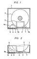
- the disk cartridge has a window portion 3 for exposing a part of a disk 2, arranged on a flat portion of a cartridge half 1 thereof, and a rail portion 4 arranged on one side edge portion of the cartridge half 1 along an external edge of the window portion 3.
- a dust-proof shutter 5 which moves in parallel fashion along the rail portion 4 to open and close the window portion 3.
- a torsion spring 6 is stretched between one side edge 5a of the dust-proof shutter 5 and a corner portion la of the cartridge half 1, which spring 6 always urges the dust-proof shutter 5 by its biasing force toward the closing direction of the window portion 3; the dust-proof shutter 5 is kept in its closed state by its other side edge 5b being abutting against a stopper projection 7 on the cartridge half 1 at a location corresponding to an end position of the rail 4.
- the torsion spring 6, which biases the dust-proof shutter 5 toward the window portion 5, flexibly moves all over the space between the side edge 5a of the dust-proof shutter 5 and one side wall of the cartridge half 1, namely a space a in the corner portion la of the cartridge half 1, during opening and closing movements of the dust-proof shutter 5, so that it is impossible to provide a projected boss e.g. for screwing and integrating the cartridge halves 1 in the space a.
- the two cartridge halves should be bonded by ultra-sonic soldering or a bonding agent. If the cartridge halves 1 are bonded as mentioned above, it becomes difficult to exchange the disk accommodated therein and further impossible to re-use the cartridge halves.
- a disk cartridge comprising: a pair of cartridge halves
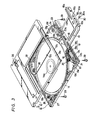
- reference numeral 11 generally designates a disk cartridge formed of a pair of an upper cartridge half 12 and a lower cartridge half 13 which are integrally coupled to each other by screws with a disk 14 accommodated therein.
- window portions 12a and 13a respectively, occupying an area from the edge portion to a portion slightly beyond the center of each cartridge half, through which are exposed a part of the disk 14 and a chucking hub 14a arranged in a central portion of the disk 14.
- guiding plane portions 12b and 13b for a sliding shutter 15 which opens and closes the window portions 12a and 13a, over an area from one side of the window portions 12a and 13a to one side of the upper and lower cartridge halves 12 and 13. Further, there are formed, on the internal front edge surfaces of the respective guiding plane portions 12b and 13b along the lateral direction, engagement guiding grooves 12c and 13c engaged with a sliding member 16 which supports the sliding shutter 15 for the disk cartridge 11.
- a first rack 17 is provided on the inner surface of the sliding member 16.
- a second rack 18 corresponding to the first rack 17 is provided in a corner portion 13e defined between the window portion 13a and a side wall 13d of the lower cartridge half 13, parallel to the guiding groove 13c.
- a pinion 19 is rotatably engaged with the first rack 17 arranged on,the sliding member 16 and the second rack 18 in a manner that the rotation of the pinion 19 and sliding of the sliding member 16 are effected relative to the second rack 18.
- a torsion spring 20 is stretched between an eccentric portion of the pinion 19 and the corner of the corner portion 13e of the cartridge half 13 in a manner that the torsion spring 20 urges the pinion 19 by its biasing to be always rotatable in mesh with the second rack 18 to the side of the window portion 13a, whereby the sliding member 16 is slid toward the front edge of the window portion 13a.
- the pinion 19 rotates with respect to the second rack 18 arranged in the cartridge half 13 within a range substantially half as much as the slidable range of the sliding member 16. Therefore, the second rack 18 is projectedly arranged in the corner portion 13e toward one side wall 13d from the window portion 13a. Further, outside the length necessary to accommodate the translational movement of the pinion 19 as it rotates, that is, in a space between the outer end of the second rack 9 and the side wall 13d, there are arranged a boss formed with hole 21 for screwing the cartridge halves and adjacent thereto, at a corner of the corner portion 13e, a projecting engaging portion 22 with which one end of the torsion spring 20 is engaged.
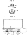
- the pinion 19 is constructed such that an outer pinion portion 19a is rotatably pivoted at a rotation axis body 19b, as shown in Figs. 6 and 7.
- the rotation axis body 19b has a step portion, the step face 19b 1 of which supports the pinion portion 19a in the axial direction. Further, the rotation axis body 19b is provided, at an eccentric position, offset from its axis with an engaging hole 19c with which the other end of the torsion spring 20 is engaged.
- a locking member 23 is arranged for locking the sliding shutter 15 in a closed state in a corner portion 13g between the window portion 13a of the lower cartridge half 13 and another side wall 13f thereof.
- a movable locking portion 23a which is engaged with an arm portion 15a of the sliding shutter 15, extends along the elongated direction of the engagement guiding groove 13c.
- there are projections or bosses providing holes 24, 25 and 26 for screwing the cartridge halves, respectively.
- the upper and lower cartridge halves 12 and 13 thus constructed and with the disk 14 accommodated therein are made unitary by screws 29 which are inserted from the lower cartridge half 13 through holes 21, 24, 25 and 26 respectively arranged at the corner portions 13e, 13g, 13h and 13i and screwed into the other cartridge half 12.
- the sliding shutter 15 is mounted on the guiding plane portions 12b and 13b of the cartridge halves 12 and 13 in a manner that the sliding shutter 15 corresponds to the window portions 12a and 13a and is then secured, by screws 30, to the front surface of the sliding member 16 engaged with the guiding grooves 12c and 13c between the front edges of the cartridge halves 12 and 13.
- the disk cartridge 11 is constituted.
- counter sunk bolts are used for the screws 30 which secures the sliding shutter 15 to the sliding member 16.
- a through-hole 15b bored through the side shutter 15 is formed as a counter sink, so that the head portions 30a of each of the screws 30 is fitted into the periphery of the through-hole 15b, without the head portion projecting beyond the front plane of the sliding shutter 15, whereby the head portions 30a of the respective screws 30 neither prevent sliding movements of a shutter loading pin 31 nor damages the aspect of the disk cartridge 11.
- the sliding shutter 15 is made of a metal plate, the through-hole 15b is formed as a punched-out shape by pressing. '
- the sliding member 16 when the sliding shutter 15 is closing the window portions 12a and 13a during non-use, the sliding member 16 is positioned at the inner end portions of the guiding grooves 12c and 13c by the pinion 19 which is biased and rotated by the spring 20 to a position in which the arm portion 15a of the sliding shutter 15 is engaged with the movable locking portion 23a of the locking member 23, so that the sliding shutter 15 is maintained in its closing state for the window portions 12a and 13a without being unnecessarily opened.
- the disk cartridge 11 is loaded on a recording/reproducing apparatus, not shown, and then driven. Then, the shutter loading pin 31 is slid along the front plane of the sliding shutter 15 to release the sliding shutter 15 from a locked state maintained by the locking member 23 and to urge the same in its opening direction. Therefore, as shown in Fig. 5, the sliding member 16 is slid along the guiding grooves 12c and 13c of the cartridge halves 12 and 13, whereby the pinion 19 rotates and moves relative to the second rack 18, against the biasing force of the torsion spring 20, and consequently the torsion spring 20 moves in the corner portion 13e while being flexed.
- the upper and lower cartridge halves 12 and 13 can be secured together by screws at each corner thereof without any trouble.
- the use of the rack-pinion mechanism the stroke of which corresponds to substantially half the sliding range of the sliding shutter for opening and closing the window portions of the disk cartridge, and the fact that one end of the torsion spring is engaged with the pinion so as to give the sliding shutter the biasing force in the closing direction for the window portions, makes it possible to reduce the area necessary for flexible movements of the torsion spring during the opening and closing movements of the sliding shutter and hence assure a sufficient space for a screw in the corner. Consequently, screws can be used to incorporate the cartridge halves, producing effects such as the facts that the disk accommodated therein can be easily exchanged even after assembling the disk cartridge and that the disk cartridges can be again used.
- the cartridge halves 12 and 13, window portions 12a and 13a and sliding shutter 15 are not limited to the shapes as shown in the drawings, neither is the construction of the other members limited to that of the present embodiment, but rather can be modified without departing from the scope of the novel concepts of the present invention as defined in the appended claims.
Landscapes
- Feeding And Guiding Record Carriers (AREA)
- Packaging For Recording Disks (AREA)
- Liquid Crystal (AREA)
- Packaging Of Annular Or Rod-Shaped Articles, Wearing Apparel, Cassettes, Or The Like (AREA)
Priority Applications (1)
| Application Number | Priority Date | Filing Date | Title |
|---|---|---|---|
| AT87303408T ATE85860T1 (de) | 1986-04-30 | 1987-04-16 | Plattenkassette. |
Applications Claiming Priority (2)
| Application Number | Priority Date | Filing Date | Title |
|---|---|---|---|
| JP61100043A JPH0682504B2 (ja) | 1986-04-30 | 1986-04-30 | デイスクカ−トリツジ |
| JP100043/86 | 1986-04-30 |
Publications (3)
| Publication Number | Publication Date |
|---|---|
| EP0244132A2 true EP0244132A2 (de) | 1987-11-04 |
| EP0244132A3 EP0244132A3 (en) | 1989-03-08 |
| EP0244132B1 EP0244132B1 (de) | 1993-02-17 |
Family
ID=14263486
Family Applications (1)
| Application Number | Title | Priority Date | Filing Date |
|---|---|---|---|
| EP87303408A Expired - Lifetime EP0244132B1 (de) | 1986-04-30 | 1987-04-16 | Plattenkassette |
Country Status (8)
| Country | Link |
|---|---|
| US (1) | US4799121A (de) |
| EP (1) | EP0244132B1 (de) |
| JP (1) | JPH0682504B2 (de) |
| KR (1) | KR960007234B1 (de) |
| AT (1) | ATE85860T1 (de) |
| AU (1) | AU591266B2 (de) |
| CA (1) | CA1277923C (de) |
| DE (1) | DE3784187T2 (de) |
Cited By (9)
| Publication number | Priority date | Publication date | Assignee | Title |
|---|---|---|---|---|
| US4791511A (en) * | 1985-09-19 | 1988-12-13 | Laser Magnetic Storage International Company | Disk cartridge with slide door engageable in either of two orientations |
| US4823214A (en) * | 1985-09-19 | 1989-04-18 | Laser Magnetic Storage International Company | Disk drive for cartridge disks |
| EP0442502A2 (de) | 1990-02-14 | 1991-08-21 | Dai Nippon Insatsu Kabushiki Kaisha | Plattenkassette |
| US5289457A (en) * | 1988-04-28 | 1994-02-22 | Dai Nippon Insatsu Kabushiki Kaisha | Disc cartridge with bent spring design for closing a closure shutter |
| GB2270194A (en) * | 1992-08-24 | 1994-03-02 | Tdk Corp | A sliding shutter for a cartridge e.g. a diskette or dat cassette |
| US5315470A (en) * | 1991-04-25 | 1994-05-24 | Sony Corporation | Disk cartridge with centered magnetic plate |
| US5323382A (en) * | 1991-07-31 | 1994-06-21 | Sony Corporation | Disc cartridge |
| US5408458A (en) * | 1988-04-28 | 1995-04-18 | Dai Nippon Insatsu Kabushiki Kaisha | Disc cartridge with shutter/slider/spring engagement portions |
| EP0778567A3 (de) * | 1990-01-29 | 1997-11-05 | Dai Nippon Insatsu Kabushiki Kaisha | Plattenkassette |
Families Citing this family (9)
| Publication number | Priority date | Publication date | Assignee | Title |
|---|---|---|---|---|
| JPH0739101Y2 (ja) * | 1988-06-29 | 1995-09-06 | 大日本印刷株式会社 | ディスクカートリッジのシャッタとスライダの固定構造 |
| JPH02110069U (de) * | 1989-02-13 | 1990-09-03 | ||
| EP0684609B1 (de) * | 1989-07-05 | 2002-01-09 | Hitachi Maxell Ltd. | Plattenkassette |
| US5249177A (en) * | 1989-09-12 | 1993-09-28 | Daicel Chemical Industries Ltd. | Structure for preventing dislocation of a spring in an optical disk cartridge |
| US5717684A (en) * | 1990-01-29 | 1998-02-10 | Dai Nippon Insatsu Kabushiki Kaisha | Disk cartridge having chamfered wall portion |
| JPH0887855A (ja) * | 1994-09-14 | 1996-04-02 | Sony Corp | ディスクカートリッジ |
| US20020118634A1 (en) * | 2001-02-28 | 2002-08-29 | Hong Khuu | Rack gear opening mechanism for an optical disk cartridge |
| JP2003100046A (ja) * | 2001-09-21 | 2003-04-04 | Pioneer Electronic Corp | ディスクカートリッジ、ディスク装置およびシャッタ開閉機構 |
| EP1542223A4 (de) * | 2002-07-26 | 2008-04-09 | Matsushita Electric Industrial Co Ltd | Scheibenvorrichtung |
Family Cites Families (9)
| Publication number | Priority date | Publication date | Assignee | Title |
|---|---|---|---|---|
| DE1774349B2 (de) * | 1967-05-31 | 1973-09-27 | Nippon Electric Co., Ltd., Tokio | Behälter für magnetische Speicherscheiben und Datenspeichereinrichtung |
| US4412260A (en) * | 1981-04-24 | 1983-10-25 | Magnetic Peripherals Inc. | Cartridge receiver mechanism |
| JPS57201674U (de) * | 1981-06-16 | 1982-12-22 | ||
| JPS59177073U (ja) * | 1983-05-13 | 1984-11-27 | ソニー株式会社 | ディスクカセット |
| DE3477620D1 (en) * | 1983-08-20 | 1989-05-11 | Hitachi Maxell | Disc cartridge |
| JPS6140753U (ja) * | 1984-08-20 | 1986-03-14 | ソニー株式会社 | カセットのシャッター開閉機構 |
| JPS6166272A (ja) * | 1984-09-10 | 1986-04-05 | Clarion Co Ltd | デイスクカ−トリツジ |
| JPS6168782A (ja) * | 1984-09-12 | 1986-04-09 | Sony Corp | デイスクカ−トリツジ |
| JPH0355188Y2 (de) * | 1985-05-20 | 1991-12-06 |
-
1986
- 1986-04-30 JP JP61100043A patent/JPH0682504B2/ja not_active Expired - Lifetime
-
1987
- 1987-04-14 AU AU71533/87A patent/AU591266B2/en not_active Expired
- 1987-04-16 AT AT87303408T patent/ATE85860T1/de not_active IP Right Cessation
- 1987-04-16 EP EP87303408A patent/EP0244132B1/de not_active Expired - Lifetime
- 1987-04-16 DE DE8787303408T patent/DE3784187T2/de not_active Expired - Lifetime
- 1987-04-21 KR KR1019870003810A patent/KR960007234B1/ko not_active Expired - Lifetime
- 1987-04-22 CA CA000535254A patent/CA1277923C/en not_active Expired - Lifetime
- 1987-04-27 US US07/042,733 patent/US4799121A/en not_active Expired - Lifetime
Cited By (17)
| Publication number | Priority date | Publication date | Assignee | Title |
|---|---|---|---|---|
| US4791511A (en) * | 1985-09-19 | 1988-12-13 | Laser Magnetic Storage International Company | Disk cartridge with slide door engageable in either of two orientations |
| US4823214A (en) * | 1985-09-19 | 1989-04-18 | Laser Magnetic Storage International Company | Disk drive for cartridge disks |
| US5444691A (en) * | 1988-04-28 | 1995-08-22 | Dai Nippon Insatsu Kabushiki Kaisha | Disc Cartridge |
| US5289457A (en) * | 1988-04-28 | 1994-02-22 | Dai Nippon Insatsu Kabushiki Kaisha | Disc cartridge with bent spring design for closing a closure shutter |
| US5408458A (en) * | 1988-04-28 | 1995-04-18 | Dai Nippon Insatsu Kabushiki Kaisha | Disc cartridge with shutter/slider/spring engagement portions |
| EP0778567A3 (de) * | 1990-01-29 | 1997-11-05 | Dai Nippon Insatsu Kabushiki Kaisha | Plattenkassette |
| US5325257A (en) * | 1990-02-14 | 1994-06-28 | Dai Nippon Insatsu Kabushiki Kaisha | Disk cartridge |
| EP0442502A3 (en) * | 1990-02-14 | 1992-03-11 | Dai Nippon Insatsu Kabushiki Kaisha | Disk cartridge |
| EP0691650A3 (de) * | 1990-02-14 | 1997-07-23 | Dainippon Printing Co Ltd | Plattenkassette |
| EP0690443A3 (de) * | 1990-02-14 | 1997-07-23 | Dainippon Printing Co Ltd | Plattenkassette |
| EP0442502A2 (de) | 1990-02-14 | 1991-08-21 | Dai Nippon Insatsu Kabushiki Kaisha | Plattenkassette |
| US5315470A (en) * | 1991-04-25 | 1994-05-24 | Sony Corporation | Disk cartridge with centered magnetic plate |
| US5323382A (en) * | 1991-07-31 | 1994-06-21 | Sony Corporation | Disc cartridge |
| AU671404B2 (en) * | 1991-07-31 | 1996-08-22 | Sony Corporation | Disc cartridge |
| GB2270194A (en) * | 1992-08-24 | 1994-03-02 | Tdk Corp | A sliding shutter for a cartridge e.g. a diskette or dat cassette |
| GB2270194B (en) * | 1992-08-24 | 1996-05-15 | Tdk Corp | Cartridge for a recording/reproducing medium and method of making the same |
| US5524005A (en) * | 1992-08-24 | 1996-06-04 | Tdk Corporation | Cartridge for a recording reproducing medium having a shutter configured to reduce damage to the casing |
Also Published As
| Publication number | Publication date |
|---|---|
| KR870010539A (ko) | 1987-11-30 |
| CA1277923C (en) | 1990-12-18 |
| JPH0682504B2 (ja) | 1994-10-19 |
| AU7153387A (en) | 1987-11-05 |
| JPS62257686A (ja) | 1987-11-10 |
| EP0244132A3 (en) | 1989-03-08 |
| US4799121A (en) | 1989-01-17 |
| DE3784187D1 (de) | 1993-03-25 |
| EP0244132B1 (de) | 1993-02-17 |
| AU591266B2 (en) | 1989-11-30 |
| KR960007234B1 (ko) | 1996-05-29 |
| ATE85860T1 (de) | 1993-03-15 |
| DE3784187T2 (de) | 1993-06-09 |
Similar Documents
| Publication | Publication Date | Title |
|---|---|---|
| EP0244132B1 (de) | Plattenkassette | |
| KR890003023B1 (ko) | 도어정 조립체 | |
| CA2002481C (en) | Disk cartridge | |
| US4579295A (en) | Brake mechanism for tape cassette | |
| US5980121A (en) | Sliding movement locking apparatus and sliding cover apparatus for a camera | |
| JP2000113630A (ja) | ディスクカートリッジ | |
| KR960013017B1 (ko) | 디스크카트리지 | |
| EP0125688B1 (de) | Bandkassette | |
| JP3318621B2 (ja) | テープカセット | |
| GB2045336A (en) | Lock for Motor Vehicle Doors | |
| US5799221A (en) | Camera | |
| US5671459A (en) | Camera cover guide mechanism | |
| KR920018740A (ko) | 테이프 카세트 | |
| JP2520300B2 (ja) | 左右両開扉装置 | |
| JP3079784B2 (ja) | ビデオデッキのカセット扉 | |
| JP2729680B2 (ja) | 引戸用自動施錠 | |
| JPS6367272B2 (de) | ||
| US4658981A (en) | Recording tape cartridge | |
| JPS62189687A (ja) | テ−プカ−トリツジ | |
| US20020118634A1 (en) | Rack gear opening mechanism for an optical disk cartridge | |
| JPH0253281A (ja) | ディスクカートリッジのシャッタ開閉機構 | |
| JP2580694B2 (ja) | ディスクカートリッジ | |
| JP4287199B2 (ja) | ディスクカートリッジ | |
| JP2570694B2 (ja) | テ−プカセツト | |
| KR0126183Y1 (ko) | 캠코더 하우징 댐퍼 장치 |
Legal Events
| Date | Code | Title | Description |
|---|---|---|---|
| PUAI | Public reference made under article 153(3) epc to a published international application that has entered the european phase |
Free format text: ORIGINAL CODE: 0009012 |
|
| 17P | Request for examination filed |
Effective date: 19870428 |
|
| AK | Designated contracting states |
Kind code of ref document: A2 Designated state(s): AT DE FR GB IT NL |
|
| PUAL | Search report despatched |
Free format text: ORIGINAL CODE: 0009013 |
|
| AK | Designated contracting states |
Kind code of ref document: A3 Designated state(s): AT DE FR GB IT NL |
|
| 17Q | First examination report despatched |
Effective date: 19910621 |
|
| GRAA | (expected) grant |
Free format text: ORIGINAL CODE: 0009210 |
|
| AK | Designated contracting states |
Kind code of ref document: B1 Designated state(s): AT DE FR GB IT NL |
|
| REF | Corresponds to: |
Ref document number: 85860 Country of ref document: AT Date of ref document: 19930315 Kind code of ref document: T |
|
| REF | Corresponds to: |
Ref document number: 3784187 Country of ref document: DE Date of ref document: 19930325 |
|
| ITF | It: translation for a ep patent filed | ||
| ET | Fr: translation filed | ||
| PLBE | No opposition filed within time limit |
Free format text: ORIGINAL CODE: 0009261 |
|
| STAA | Information on the status of an ep patent application or granted ep patent |
Free format text: STATUS: NO OPPOSITION FILED WITHIN TIME LIMIT |
|
| 26N | No opposition filed | ||
| ITTA | It: last paid annual fee | ||
| REG | Reference to a national code |
Ref country code: GB Ref legal event code: IF02 |
|
| PGFP | Annual fee paid to national office [announced via postgrant information from national office to epo] |
Ref country code: NL Payment date: 20060403 Year of fee payment: 20 |
|
| PGFP | Annual fee paid to national office [announced via postgrant information from national office to epo] |
Ref country code: FR Payment date: 20060410 Year of fee payment: 20 |
|
| PGFP | Annual fee paid to national office [announced via postgrant information from national office to epo] |
Ref country code: GB Payment date: 20060412 Year of fee payment: 20 Ref country code: AT Payment date: 20060412 Year of fee payment: 20 |
|
| PGFP | Annual fee paid to national office [announced via postgrant information from national office to epo] |
Ref country code: DE Payment date: 20060413 Year of fee payment: 20 |
|
| PGFP | Annual fee paid to national office [announced via postgrant information from national office to epo] |
Ref country code: IT Payment date: 20060430 Year of fee payment: 20 |
|
| PG25 | Lapsed in a contracting state [announced via postgrant information from national office to epo] |
Ref country code: NL Free format text: LAPSE BECAUSE OF EXPIRATION OF PROTECTION Effective date: 20070416 |
|
| REG | Reference to a national code |
Ref country code: GB Ref legal event code: PE20 |
|
| NLV7 | Nl: ceased due to reaching the maximum lifetime of a patent |
Effective date: 20070416 |
|
| PG25 | Lapsed in a contracting state [announced via postgrant information from national office to epo] |
Ref country code: GB Free format text: LAPSE BECAUSE OF EXPIRATION OF PROTECTION Effective date: 20070415 |