EP0244811A2 - Installation pour le nettoyage des tuyauteries - Google Patents
Installation pour le nettoyage des tuyauteries Download PDFInfo
- Publication number
- EP0244811A2 EP0244811A2 EP87106459A EP87106459A EP0244811A2 EP 0244811 A2 EP0244811 A2 EP 0244811A2 EP 87106459 A EP87106459 A EP 87106459A EP 87106459 A EP87106459 A EP 87106459A EP 0244811 A2 EP0244811 A2 EP 0244811A2
- Authority
- EP
- European Patent Office
- Prior art keywords
- compressed air
- pressure
- water
- supply
- inlet
- Prior art date
- Legal status (The legal status is an assumption and is not a legal conclusion. Google has not performed a legal analysis and makes no representation as to the accuracy of the status listed.)
- Granted
Links
Images


Classifications
-
- B—PERFORMING OPERATIONS; TRANSPORTING
- B08—CLEANING
- B08B—CLEANING IN GENERAL; PREVENTION OF FOULING IN GENERAL
- B08B9/00—Cleaning hollow articles by methods or apparatus specially adapted thereto
- B08B9/02—Cleaning pipes or tubes or systems of pipes or tubes
- B08B9/027—Cleaning the internal surfaces; Removal of blockages
- B08B9/032—Cleaning the internal surfaces; Removal of blockages by the mechanical action of a moving fluid, e.g. by flushing
- B08B9/0321—Cleaning the internal surfaces; Removal of blockages by the mechanical action of a moving fluid, e.g. by flushing using pressurised, pulsating or purging fluid
- B08B9/0325—Control mechanisms therefor
-
- B—PERFORMING OPERATIONS; TRANSPORTING
- B08—CLEANING
- B08B—CLEANING IN GENERAL; PREVENTION OF FOULING IN GENERAL
- B08B9/00—Cleaning hollow articles by methods or apparatus specially adapted thereto
- B08B9/02—Cleaning pipes or tubes or systems of pipes or tubes
- B08B9/027—Cleaning the internal surfaces; Removal of blockages
- B08B9/032—Cleaning the internal surfaces; Removal of blockages by the mechanical action of a moving fluid, e.g. by flushing
- B08B9/0321—Cleaning the internal surfaces; Removal of blockages by the mechanical action of a moving fluid, e.g. by flushing using pressurised, pulsating or purging fluid
- B08B9/0328—Cleaning the internal surfaces; Removal of blockages by the mechanical action of a moving fluid, e.g. by flushing using pressurised, pulsating or purging fluid by purging the pipe with a gas or a mixture of gas and liquid
-
- E—FIXED CONSTRUCTIONS
- E03—WATER SUPPLY; SEWERAGE
- E03C—DOMESTIC PLUMBING INSTALLATIONS FOR FRESH WATER OR WASTE WATER; SINKS
- E03C1/00—Domestic plumbing installations for fresh water or waste water; Sinks
- E03C1/12—Plumbing installations for waste water; Basins or fountains connected thereto; Sinks
- E03C1/30—Devices to facilitate removing of obstructions in waste-pipes or sinks
- E03C1/304—Devices to facilitate removing of obstructions in waste-pipes or sinks using fluid under pressure
Definitions
- the invention relates to a device for cleaning pipes with an inlet connection for the supply of liquid and an outlet connection for connection to the pipe to be flushed, and with a supply for the compressed air.
- a water supply and a gas supply are alternately connected to the pipeline via respective valves.
- the object of the invention is to provide a device of the type described at the outset which is simple in design and with which quick and reliable cleaning is possible.
- a device of the type described at the outset which is characterized according to the invention by a controller for controlling the compressed air supply and a water meter for measuring the liquid flowing through, the output signal of which is fed to the input of the controller.
- a pressure regulator is provided, the input of which is connected to the inlet side of the water supply and which is designed in such a way that a preset ratio between liquid pressure and air pressure is achieved. This ensures that the pregiven level air pressure is kept constant even when the water pressure changes, for example during a withdrawal on the inlet side.
- the pressure regulator is designed as a differential pressure regulator, so that, for example, the air pressure is always greater than the actual water pressure by a predetermined value.
- the pressure regulator has an oil or water filter in its passage for the compressed air.
- a compressor is preferably provided on the input side of the compressed air supply and is mounted together with the other components on a chassis. This ensures that the entire facility is mobile and can be moved directly to the place of use, which is particularly important for use on construction sites.
- the device comprises a pipe section 1 to be coupled between a water supply and the pipeline to be flushed, with an inlet-side connection 2 for connecting to the liquid supply and an outlet-side connection 3 for connecting to the pipeline to be flushed.
- a water meter 4 is provided in the form of a pulse water meter for measuring the flow.
- the output side of the pulse water meter is connected to the input of a controller 5.
- a compressor 6 is also provided.
- the output side of the compressor is connected to the input of an automatic pressure regulator 8 via a compressed air line 7.
- the output of the pressure regulator 8 leads via the compressed air line to an inlet of a solenoid valve 9.
- the outlet of the solenoid valve is connected to the inlet of a throttle check valve 10.
- the outlet of the throttle check valve leads into the pipe section 1 at a compressed air supply point 11.
- a check valve 12 is provided, which blocks flow back in the direction from port 3 to port 2.
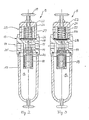
- the pressure regulator 8 is designed as a differential pressure regulator.
- This has a control head 13 which is connected on its underside to a cup-like hood 15.
- the control head has an inlet 14 to be connected via the pressure line 7 to the compressor 6, which opens into the interior 16 enclosed by the hood 15.
- an output 17 is provided which is arranged coaxially to the input 14 and which leads to the interior 16 via a bore.
- an oil or water filter 18 is screwed interchangeably.
- a check valve 19 is provided between the oil or water filter and the outlet 17. The valve body of this check valve is biased into its locked position by means of a spring 20.
- the control head is also connected to a pressure chamber housing 22 which forms a pressure chamber 21.
- the interior of the pressure chamber has an inlet 23 which, as can be seen in FIG. 1, is connected to an outlet of the water meter 4 via a control line 24.
- a diaphragm 26 is clamped between the pressure chamber housing 22 and the housing of the control head 13 perpendicular to the displacement path of the valve body 25 of the check valve 19.
- the membrane On the side facing the pressure chamber interior, the membrane is acted upon by a compression spring 27, the other end of which rests against an inner wall of the pressure chamber interior opposite the membrane.
- the membrane 26 On its side opposite the compression spring 27, the membrane 26 is connected to the valve body 25 via a tappet 28.
- the pressure of the spring 27 is adjustable by means of a manual setting device 29.
- a metering pump 30 is also provided, which is connected on the inlet side to a suction lance 31 for sucking in metering agent and on the outlet side via a check valve 32 to the pipe section 1 or an additional pipe section 33 to be coupled in.
- the metering pump 30 and the suction lance 31 are connected to the controller 5 via control lines and a connector plug 34 via a corresponding connection socket 35 and corresponding control lines.
- water flows through the pipe section 1 via the inlet-side connection 2.
- the water meter 4 gives electrical pulses to the electronic control 5 depending on the flow rate. This controls the solenoid valve 9 and thus connects or disconnects the compressor 6 to the compressed air supply point 11.
- the compressed air flows through the throttle check valve 10 into the pipe section 1.
- the water flow is interrupted for the duration of an incoming air pulse, and the water is mixed with compressed air. Since the inlet-side water pressure is applied to the pressure chamber 21 via the control line 24, the required air pressure is automatically regulated as a function of the prevailing water pressure.
- the dimensioning of the size of the diaphragm 26 and the strength of the compression spring 27 is selected so that when the water pressure in the pressure chamber 21 is present, the shut-off valve 19 opens so far in the manner shown in FIG 17 there is an air pressure which is higher than the existing water pressure by a predetermined value.
- the air pressure is preferably one bar higher than the existing water pressure, for example.
- an air manometer 36 and a water manometer 37 are also provided, on which the prevailing pressures can be read.
- the controller 5 is designed so that the device described above can be operated in four different operating positions. First, the device can be operated as a normal compressor. The air is led directly from the compressor 6 to the consumption point.
- a third operating position chemicals are dosed in addition to the pipe rinsing.
- the metering device 30 and the suction lance 31 are controlled like a conventional metering device via the controller 5 as a function of the water meter 4 for the quantitative metering of a chemical into the pipe section 1 or the pipe section 33.
- the compressor is switched off in one switching position, while it is also switched on in another operating mode.
- the entire device with the compressor 6 with an associated pressure vessel 38, the controller 5, the water meter 4, the pressure regulator 8 and the pipe section 1 with its connections is mounted on a chassis 39. In this way it is possible to drive the entire device with this chassis directly to the place of use and to put it into operation immediately after connecting it to the pipe to be flushed.
Landscapes
- Engineering & Computer Science (AREA)
- Mechanical Engineering (AREA)
- Environmental & Geological Engineering (AREA)
- Health & Medical Sciences (AREA)
- Life Sciences & Earth Sciences (AREA)
- Hydrology & Water Resources (AREA)
- Public Health (AREA)
- Water Supply & Treatment (AREA)
- Pipeline Systems (AREA)
- Cleaning In General (AREA)
- Sewage (AREA)
Priority Applications (1)
| Application Number | Priority Date | Filing Date | Title |
|---|---|---|---|
| AT87106459T ATE55290T1 (de) | 1986-05-05 | 1987-05-05 | Einrichtung zum reinigen von rohrleitungen. |
Applications Claiming Priority (2)
| Application Number | Priority Date | Filing Date | Title |
|---|---|---|---|
| DE19863615171 DE3615171A1 (de) | 1986-05-05 | 1986-05-05 | Einrichtung zum reinigen von rohrleitungen |
| DE3615171 | 1986-05-05 |
Publications (3)
| Publication Number | Publication Date |
|---|---|
| EP0244811A2 true EP0244811A2 (fr) | 1987-11-11 |
| EP0244811A3 EP0244811A3 (en) | 1989-02-08 |
| EP0244811B1 EP0244811B1 (fr) | 1990-08-08 |
Family
ID=6300206
Family Applications (1)
| Application Number | Title | Priority Date | Filing Date |
|---|---|---|---|
| EP87106459A Expired - Lifetime EP0244811B1 (fr) | 1986-05-05 | 1987-05-05 | Installation pour le nettoyage des tuyauteries |
Country Status (4)
| Country | Link |
|---|---|
| EP (1) | EP0244811B1 (fr) |
| JP (1) | JPS6316084A (fr) |
| AT (1) | ATE55290T1 (fr) |
| DE (1) | DE3615171A1 (fr) |
Cited By (12)
| Publication number | Priority date | Publication date | Assignee | Title |
|---|---|---|---|---|
| FR2632548A1 (fr) * | 1988-06-09 | 1989-12-15 | Geophysique Etudes Detartrages | Procede et dispositif pour le debourbage d'installations de chauffage central |
| EP0326867A3 (en) * | 1988-02-05 | 1990-11-07 | Karl Muller | Method for cleaning and coating pipe systems for water transport |
| EP0584345A4 (fr) * | 1992-03-11 | 1995-01-25 | Plummer Design & Technologies | Procede et appareil de nettoyage de tuyaux. |
| DE19701010A1 (de) * | 1997-01-14 | 1998-07-16 | Josef Stoeckl | Verfahren zur Sanierung der Innenwände festverlegter Rohrleitungen |
| EP0864378A1 (fr) * | 1997-03-14 | 1998-09-16 | Walter Lippuner | Dispositif de nettoyage pour conduits d'huile |
| DE19745642C5 (de) * | 1997-10-15 | 2004-12-02 | Michael Schaaf | Verfahren zur Sanierung von zur Wasserführung bestimmten inkrustierten Rohrleitungen durch Reinigung und Beschichtung |
| DE10323298B4 (de) * | 2003-05-21 | 2007-03-08 | Herbert Grunwald | Verfahren zur Sanierung von inkrustierten Wasserrohrleitungen |
| EP1818113A1 (fr) * | 2006-02-13 | 2007-08-15 | Felipe Romero Huesca | Machine pour désincruster des systèmes ou circuits de tuyaux |
| EP1894638A1 (fr) * | 2006-09-02 | 2008-03-05 | Jung Pumpen GmbH | Procédé destiné à laver une conduite sous pression et dispositif d'évacuation des eaux usées |
| US10335467B2 (en) | 2002-12-31 | 2019-07-02 | Csl Behring L.L.C. | Methods of treatment using alpha-1-antitrypsin compositions |
| EP2816231B1 (fr) | 2013-06-21 | 2020-08-26 | REMS GmbH & Co KG | Appareil de rinçage et/ou de contrôle de la pression et de l'étanchéité de conduites, notamment de systèmes d'eau potable et/ou de chauffage |
| US20230250622A1 (en) * | 2022-02-08 | 2023-08-10 | Nathaniel A. Moore | Mobile plumbing tool for unclogging drain pipes with air-pressurized water |
Families Citing this family (3)
| Publication number | Priority date | Publication date | Assignee | Title |
|---|---|---|---|---|
| DE4438939C2 (de) * | 1994-10-31 | 1997-02-13 | Kanal Sanierung Halle Gmbh | Verfahren und Einrichtung zum Reinigen von Trinkwasserleitungen und zum Spülen von Trinkwasserleitungsnetzen |
| DE29500218U1 (de) * | 1995-01-07 | 1995-03-02 | Bossert, Gerdi, 78052 Villingen-Schwenningen | Reinigungsvorrichtung für Wasserleitungen |
| DE10204737B4 (de) * | 2002-02-06 | 2010-01-07 | Eam-Wasserversorgung Gmbh | Vorrichtung zum Spülen und Reinigen einer Rohrleitung, insbesondere einer Trinkwasserleitung |
Family Cites Families (2)
| Publication number | Priority date | Publication date | Assignee | Title |
|---|---|---|---|---|
| FR1401746A (fr) * | 1964-07-06 | 1965-06-04 | Torkret Gmbh | Dispositif pour le nettoyage des conduites tubulaires pour le transport du béton |
| CH662070A5 (en) * | 1984-08-16 | 1987-09-15 | Fischer Ag Georg | Process and device for flushing and cleaning a pipeline |
-
1986
- 1986-05-05 DE DE19863615171 patent/DE3615171A1/de not_active Withdrawn
-
1987
- 1987-05-01 JP JP62106460A patent/JPS6316084A/ja active Pending
- 1987-05-05 AT AT87106459T patent/ATE55290T1/de not_active IP Right Cessation
- 1987-05-05 EP EP87106459A patent/EP0244811B1/fr not_active Expired - Lifetime
Cited By (14)
| Publication number | Priority date | Publication date | Assignee | Title |
|---|---|---|---|---|
| EP0326867A3 (en) * | 1988-02-05 | 1990-11-07 | Karl Muller | Method for cleaning and coating pipe systems for water transport |
| FR2632548A1 (fr) * | 1988-06-09 | 1989-12-15 | Geophysique Etudes Detartrages | Procede et dispositif pour le debourbage d'installations de chauffage central |
| EP0584345A4 (fr) * | 1992-03-11 | 1995-01-25 | Plummer Design & Technologies | Procede et appareil de nettoyage de tuyaux. |
| DE19701010A1 (de) * | 1997-01-14 | 1998-07-16 | Josef Stoeckl | Verfahren zur Sanierung der Innenwände festverlegter Rohrleitungen |
| EP0864378A1 (fr) * | 1997-03-14 | 1998-09-16 | Walter Lippuner | Dispositif de nettoyage pour conduits d'huile |
| DE19745642C5 (de) * | 1997-10-15 | 2004-12-02 | Michael Schaaf | Verfahren zur Sanierung von zur Wasserführung bestimmten inkrustierten Rohrleitungen durch Reinigung und Beschichtung |
| US10335467B2 (en) | 2002-12-31 | 2019-07-02 | Csl Behring L.L.C. | Methods of treatment using alpha-1-antitrypsin compositions |
| DE10323298B4 (de) * | 2003-05-21 | 2007-03-08 | Herbert Grunwald | Verfahren zur Sanierung von inkrustierten Wasserrohrleitungen |
| EP1818113A1 (fr) * | 2006-02-13 | 2007-08-15 | Felipe Romero Huesca | Machine pour désincruster des systèmes ou circuits de tuyaux |
| EP1894638A1 (fr) * | 2006-09-02 | 2008-03-05 | Jung Pumpen GmbH | Procédé destiné à laver une conduite sous pression et dispositif d'évacuation des eaux usées |
| EP2816231B1 (fr) | 2013-06-21 | 2020-08-26 | REMS GmbH & Co KG | Appareil de rinçage et/ou de contrôle de la pression et de l'étanchéité de conduites, notamment de systèmes d'eau potable et/ou de chauffage |
| EP2816231B2 (fr) † | 2013-06-21 | 2023-05-10 | REMS GmbH & Co KG | Appareil de rinçage et/ou de contrôle de la pression et de l'étanchéité de conduites, notamment de systèmes d'eau potable et/ou de chauffage |
| US20230250622A1 (en) * | 2022-02-08 | 2023-08-10 | Nathaniel A. Moore | Mobile plumbing tool for unclogging drain pipes with air-pressurized water |
| US12098531B2 (en) * | 2022-02-08 | 2024-09-24 | Nathaniel A. Moore | Mobile plumbing tool for unclogging drain pipes with air-pressurized water |
Also Published As
| Publication number | Publication date |
|---|---|
| JPS6316084A (ja) | 1988-01-23 |
| ATE55290T1 (de) | 1990-08-15 |
| DE3615171A1 (de) | 1987-11-12 |
| EP0244811B1 (fr) | 1990-08-08 |
| EP0244811A3 (en) | 1989-02-08 |
Similar Documents
| Publication | Publication Date | Title |
|---|---|---|
| EP0244811B1 (fr) | Installation pour le nettoyage des tuyauteries | |
| WO1986004530A1 (fr) | Procede et dispositif pour nettoyer une tuyauterie | |
| DE2500040A1 (de) | Selbsttaetige steuervorrichtung fuer den einlass eines verdichters | |
| DE602004009343T2 (de) | Dosiersystem zur dosierung eines flüssigzusatzes in eine druckwasserleitung | |
| DE3134911C2 (de) | Dosierpumpe zum Dosieren eines Dosiermittels in ein Medium | |
| DE3902116C1 (en) | Device for adding a fluid additive, such as liquid soap or deodorant, to shower water | |
| CH668924A5 (de) | Einrichtung zur spuelung und reinigung einer rohrleitung. | |
| DE3537186A1 (de) | Sicherheitsvorrichtung gegen ueberschwemmung bei fluessigkeitsfuehrenden haushaltgeraeten | |
| DE102006021800B3 (de) | Armaturenbausatz zum Be- oder Nachfüllen von Heizungssystemen | |
| DE3002216C2 (de) | Schwimmerrückschlagventil | |
| DE8612302U1 (de) | Einrichtung zum Reinigen von Rohrleitungen | |
| DE102009017126B4 (de) | Verfahren zur Wasseraufbereitung sowie Einrichtung hierfür | |
| DE19525061A1 (de) | Regelsystem zur Regelung von Durchflußmindestmengen und Rückschlagventil | |
| DE3026994C2 (de) | Vorrichtung zum Flüssigkeitswechsel, insbesondere bei Kraftfahrzeugen | |
| DE102005003661B4 (de) | Venturi-Mischdüse | |
| DE1577536A1 (de) | Sandstrahlgeblaese | |
| EP0179271A2 (fr) | Dispositif d'alimentation pour le remplissage d'installations de chauffage fermées | |
| DE19510733C2 (de) | Vorrichtung bei einem Warmwasserbereiter zum Vermeiden des Tropfens | |
| DE69211240T2 (de) | Filter für die Beschichtung einer automatischen und/oder Verfahrenseinrichtung mit Proben für physicochemische Analysen | |
| EP0740083A2 (fr) | Vanne d'arrêt avec une piston de vanne distributrice | |
| DE2742333C2 (de) | Auflockerungsvorrichtung | |
| DE941655C (de) | Einrichtung zum Betanken zweier voneinander unabhaengiger Systeme mittels einer Pumpe | |
| DE2156699C3 (de) | Verfahren und Vorrichtung zum automatischen Regenerieren von KupferchloridÄtzmittellösungen | |
| DE102004013001A1 (de) | Anordnung zum Einbringen von Gas in eine Flüssigkeit | |
| DE241961C (fr) |
Legal Events
| Date | Code | Title | Description |
|---|---|---|---|
| PUAI | Public reference made under article 153(3) epc to a published international application that has entered the european phase |
Free format text: ORIGINAL CODE: 0009012 |
|
| AK | Designated contracting states |
Kind code of ref document: A2 Designated state(s): AT CH FR IT LI |
|
| PUAL | Search report despatched |
Free format text: ORIGINAL CODE: 0009013 |
|
| AK | Designated contracting states |
Kind code of ref document: A3 Designated state(s): AT CH FR IT LI |
|
| 17P | Request for examination filed |
Effective date: 19890222 |
|
| 17Q | First examination report despatched |
Effective date: 19891221 |
|
| GRAA | (expected) grant |
Free format text: ORIGINAL CODE: 0009210 |
|
| AK | Designated contracting states |
Kind code of ref document: B1 Designated state(s): AT CH FR IT LI |
|
| REF | Corresponds to: |
Ref document number: 55290 Country of ref document: AT Date of ref document: 19900815 Kind code of ref document: T |
|
| ET | Fr: translation filed | ||
| ITF | It: translation for a ep patent filed | ||
| PGFP | Annual fee paid to national office [announced via postgrant information from national office to epo] |
Ref country code: FR Payment date: 19910516 Year of fee payment: 5 |
|
| PGFP | Annual fee paid to national office [announced via postgrant information from national office to epo] |
Ref country code: AT Payment date: 19910527 Year of fee payment: 5 |
|
| ITTA | It: last paid annual fee | ||
| PLBE | No opposition filed within time limit |
Free format text: ORIGINAL CODE: 0009261 |
|
| STAA | Information on the status of an ep patent application or granted ep patent |
Free format text: STATUS: NO OPPOSITION FILED WITHIN TIME LIMIT |
|
| PGFP | Annual fee paid to national office [announced via postgrant information from national office to epo] |
Ref country code: CH Payment date: 19910617 Year of fee payment: 5 |
|
| 26N | No opposition filed | ||
| PG25 | Lapsed in a contracting state [announced via postgrant information from national office to epo] |
Ref country code: AT Effective date: 19920505 |
|
| PG25 | Lapsed in a contracting state [announced via postgrant information from national office to epo] |
Ref country code: LI Effective date: 19920531 Ref country code: CH Effective date: 19920531 |
|
| PG25 | Lapsed in a contracting state [announced via postgrant information from national office to epo] |
Ref country code: FR Effective date: 19930129 |
|
| REG | Reference to a national code |
Ref country code: CH Ref legal event code: PL |
|
| REG | Reference to a national code |
Ref country code: FR Ref legal event code: ST |
|
| PG25 | Lapsed in a contracting state [announced via postgrant information from national office to epo] |
Ref country code: IT Free format text: LAPSE BECAUSE OF NON-PAYMENT OF DUE FEES;WARNING: LAPSES OF ITALIAN PATENTS WITH EFFECTIVE DATE BEFORE 2007 MAY HAVE OCCURRED AT ANY TIME BEFORE 2007. THE CORRECT EFFECTIVE DATE MAY BE DIFFERENT FROM THE ONE RECORDED. Effective date: 20050505 |