EP2816231B2 - Appareil de rinçage et/ou de contrôle de la pression et de l'étanchéité de conduites, notamment de systèmes d'eau potable et/ou de chauffage - Google Patents
Appareil de rinçage et/ou de contrôle de la pression et de l'étanchéité de conduites, notamment de systèmes d'eau potable et/ou de chauffage Download PDFInfo
- Publication number
- EP2816231B2 EP2816231B2 EP14001893.8A EP14001893A EP2816231B2 EP 2816231 B2 EP2816231 B2 EP 2816231B2 EP 14001893 A EP14001893 A EP 14001893A EP 2816231 B2 EP2816231 B2 EP 2816231B2
- Authority
- EP
- European Patent Office
- Prior art keywords
- compressed air
- pressure
- water
- valve
- line
- Prior art date
- Legal status (The legal status is an assumption and is not a legal conclusion. Google has not performed a legal analysis and makes no representation as to the accuracy of the status listed.)
- Active
Links
Images
Classifications
-
- F—MECHANICAL ENGINEERING; LIGHTING; HEATING; WEAPONS; BLASTING
- F04—POSITIVE - DISPLACEMENT MACHINES FOR LIQUIDS; PUMPS FOR LIQUIDS OR ELASTIC FLUIDS
- F04B—POSITIVE-DISPLACEMENT MACHINES FOR LIQUIDS; PUMPS
- F04B35/00—Piston pumps specially adapted for elastic fluids and characterised by the driving means to their working members, or by combination with, or adaptation to, specific driving engines or motors, not otherwise provided for
- F04B35/06—Mobile combinations
-
- F—MECHANICAL ENGINEERING; LIGHTING; HEATING; WEAPONS; BLASTING
- F04—POSITIVE - DISPLACEMENT MACHINES FOR LIQUIDS; PUMPS FOR LIQUIDS OR ELASTIC FLUIDS
- F04B—POSITIVE-DISPLACEMENT MACHINES FOR LIQUIDS; PUMPS
- F04B41/00—Pumping installations or systems specially adapted for elastic fluids
- F04B41/02—Pumping installations or systems specially adapted for elastic fluids having reservoirs
Definitions
- the invention relates to a device for flushing and for testing the pressure and tightness of pipes in drinking water and/or heating systems.
- Analogue and digital pressure testers are known with which lines can be tested for pressure and tightness.
- the devices are equipped with hand pumps with which a certain pressure can be applied.
- the regulations prescribe ever higher pressures for the pressure and leak test.
- such pressures can no longer be generated with hand pumps.
- it is necessary to use electric pumps in addition to the devices which not only require an additional, expensive device, but also complicate the testing process due to the cumbersome handling.
- the pamphlet CA-A1-2 639 600 discloses a device for checking valves, the device having a line with a water connection, an air connection and an outlet for connection to the valves to be checked. There is a valve in each of the water connection and the air connection.
- the invention is based on the object of designing the generic device in such a way that it can be used to carry out the required flushing in a cost-effective and simple manner and/or tests of the piping systems can be carried out.
- the device preferably has at least one pressure generator, which is arranged on the base frame and can apply the high pressure required for the test according to EN 806-4.
- the device is equipped with a compressor and/or a pump for this purpose.
- the required test pressure can be generated with these pressure generators. Therefore, no additional devices are required in addition to the device according to the invention. The craftsman can therefore easily carry out the necessary tests of the line systems.
- the pressure generator can be used for the pressure test with air or for the pressure test with water.
- the device has at least one water line which is provided with a connection for the water network and with an outlet to which a hose can be connected, for example, which connects the device to the line system to be tested.
- At least one compressed air line via which compressed air can be supplied, opens into the water line. This makes it possible to introduce a water-compressed air mixture into the line system. This procedure is used when flushing the pipe systems. Since the switching valve is located in the compressed air line, access of the compressed air to the water line can be released or blocked as required. It is therefore possible with the device to flush the lines either with water alone or with a mixture of water and compressed air.
- the switching valve is advantageously a 3/2-way valve.
- the compressed air can be supplied continuously or else in pulses.
- the user of the device according to the invention has the option, depending on the existing conditions to select the most favorable flushing method with and without compressed air, whereby the compressed air can also be supplied continuously or in pulses.
- At least one compressor is located in the compressed air line, with which the compressed air pressure required for the respective application can be easily generated.
- At least one compressed air tank is advantageously connected downstream of the compressor. This ensures that a sufficient amount of compressed air is available as soon as the device is switched on. With the compressor, the compressed air tank can be refilled with compressed air in a simple manner.
- Another compressed air line is connected to the switching valve. It is provided with a connection to which the line system to be tested can be connected with a hose or similar. A pressure test with compressed air is therefore possible via this connection. In the other compressed air line sits another switching valve with which the other compressed air line can be opened or blocked, depending on the test to be carried out by the user of the device.
- the further switching valve advantageously forms a changeover switch for a pressure test with air or with liquid, preferably with water. Depending on the switching position of this additional switching valve, the user of the device can select the medium required for the test.
- the further switching valve is preferably a 3/2-way valve.
- an air supply line is connected to the further switching valve, which in turn connects this further switching valve to a pressure generator for the liquid medium.
- the device can thus be switch from a pressure test with air to a pressure test with liquid, especially water.
- the compressed air tank is formed by a base frame of the base frame of the device according to the invention.
- the base frame is correspondingly hollow and pressure-tight. A separate container to be attached to the base frame, which would require additional installation space, is therefore not required as a compressed air container.
- the base frame is already provided on the device, so that no additional installation space is required. As a result, the device according to the invention can be made very compact.
- the base frame is advantageously mirror-symmetrical to the longitudinal center plane of the base frame.
- This design of the base frame enables the various components of the device to be mounted in a space-saving manner and contributes to a compact design.
- this design allows the center of gravity of the device to be set favorably.
- the base frame has two U-shaped frame parts which are arranged upright and merge into one another by two horizontal frame parts.
- the U-shaped frame parts are advantageously provided opposite one another on the device.
- the legs of these frame parts advantageously extend downwards, so that the horizontal frame parts are arranged in the lower area of the device.
- This training contributes to a favorable low center of gravity of the device, making the handling of the device is much easier.
- the base frame with the frame parts can be produced very easily because tubes can be used as the starting material, which can be easily bent into the desired shape and then connected to one another in a pressure-tight manner in a suitable manner, for example by a welding process.
- the U-shaped frame parts are advantageously bent in such a way that they have a part of the horizontal frame parts.
- the horizontal frame parts of the two U-shaped frame parts are welded together, resulting in the base frame.
- a floor is advantageously fastened to the horizontal frame parts of the base frame.
- the various components and units of the device can be mounted on it.
- the base frame thus not only has the function of a compressed air tank, but also serves as a supporting frame with which the components mounted on the floor and/or on the base frame are carried.
- a standing partition wall is arranged on the floor.
- the partition wall can be designed in such a way that it optimally shields the components on one side and on the other side from one another, so that these components cannot influence one another.
- the dividing wall can be designed as a heat protection wall, which ensures that the heat generated by individual units during operation of the device is dissipated in such a way that other components are not affected by the heat.
- the device can be constructed in such a way that the heat-insensitive components are located on one side of the partition wall, while the heat-generating components, such as the compressor or the pump, are arranged on the other side.
- the partition wall is also suitable as a mounting wall to which the components of the device can be attached.
- the switching valves are advantageously connected to a controller. With the control, the switching valves can be switched by the operator to the desired extent.
- the device is advantageously provided with at least one control panel with input elements for input of data and/or commands into the controller.
- the user can make the necessary entries for the respective application on the control panel. For example, he can set the device for a flushing process or for a pressure and leak test.
- the device can also have a connection for an air-powered tool.
- This connection is advantageously connected to the compressed air tank.
- the user of the device has the option not only of flushing or checking the line systems, but also of carrying out any installation work associated with the laying of lines using appropriate tools operated by compressed air.
- the device according to the invention enables the user to carry out a wide variety of functions, for which only the single device is necessary and additional devices are not required.
- the device gives the user the ability to perform the eight functions listed above without requiring additional devices.
- the device can also be equipped in such a way that only function 5 or function 8 or both functions 5 and 8 can be performed with it. It is also possible to equip the device in such a way that it can perform functions 1 to 7. In the maximum configuration, the device can perform all functions 1 to 8.
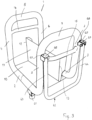
- the device has a base frame 1 ( 3 ), which has two parallel frame parts 2, 3.
- the two frame parts 2, 3 go at both ends curved in an arc in upward frame parts 4, 5; 6, 7 over.
- the frame parts 4 to 7 run parallel to one another and perpendicular to the two lower frame parts 2, 3.
- the frame parts 4, 6 curve into a frame part 8 and the frame parts 5, 7 curve into a frame part 9.
- the two frame parts 8, 9 are parallel to each other and advantageously at the same height.
- the base frame 1 is formed on the two long sides of the device by the U-shaped mutually lying frame parts 2, 4, 5 and 3, 6, 7, which are connected to each other by the upper frame part 9, 8.
- These U-shaped frame areas are characterized in that the frame parts 4, 5 and 6, 7 run upwards from the lower frame part 2, 3.
- the base frame 1 is formed by the frame parts 4, 6, 8 and 5, 7, 9 arranged in a U-shape, the frame parts 4, 6 and 5, 7 extending downwards from the upper frame part 8, 9 extend.
- the U-shaped frame parts are made from two tubes. They are bent in such a way that the U-shaped frame parts 4, 6, 8 and 5, 7, 9 still have part of the horizontal frame parts 2, 3.
- the frame parts bent in this way are placed together with the horizontal sections and welded together in a pressure-tight manner.
- the horizontal sections form the frame parts 2, 3 of the base frame 1.
- the weld which is advantageously located halfway along the frame parts 2, 3, is in 3 indicated by a dashed line.
- the device Due to the design of the base frame 1 described, the device has a high rigidity.
- a partition 11 which is vertical extends to the floor 10 and is fixed on it.
- the partition wall 11 is also advantageously formed by a plate which, in the exemplary embodiment, has a rectangular outline and extends over the entire length of the floor 10 .
- the upward narrow sides 12, 13 of the partition 11 are each angled.
- the narrow side 12 is angled in a U-shape.
- the opposite narrow side 13 is only bent at right angles.
- the shape of these narrow sides 12, 13 depends on those units that are to be mounted on the floor 10 and/or on the partition wall 11.
- the two frame parts 4, 6 are connected to one another by a cross brace 14, which is located at a small distance below the frame part 8.
- the opposite vertical frame parts 5, 7 are connected to one another at a small distance below the frame part 9 by a cross brace 15.
- the two crossbars 14, 15 are at the same height, but can also be provided at different heights, depending on the design of the device.
- the partition wall 11 can vary in height depending on the structure of the device. In the illustrated embodiment, the upper edge of the partition wall 11 is at a distance in the area below the cross braces 14, 15, viewed in the longitudinal direction of the frame parts 2, 3.
- the base frame 1 not only has a support and carrying function for the device and the units, but also serves as a compressed air tank. Accordingly, the frame parts 2 to 9 are formed by tubes which are connected to one another in a pressure-tight manner. Therefore, no separate container for the compressed air is required, so that the device can be made compact overall.
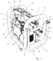
- the device has a water connection 16 via which the device can be connected to the water supply.
- a pressure transducer 18 which is a water meter 19 and a check valve 20 in the water line 17 downstream.
- the check valve 20 prevents the water from flowing back towards the water connection 16 .
- the water line 17 has an outlet 21 through which the water enters the water lines of the respective installation that are to be rinsed and/or tested.
- the outlet 21, like the water connection 16, is designed as a coupling, so that a simple connection to the water network or to the installation water lines, if necessary using pieces of hose, is possible.
- the water line 17 runs, as can be seen from the 1 and 2 results, essentially horizontally through the device.
- the water connection 16 is located in the area between the upper frame part 8 and the crossbar 14.
- the outlet 21 on the opposite side of the device is located between the upper frame part 9 and the crossbar 15.
- the water connection 16 protrudes and/or the outlet 21 slightly outwards. Since the water connection 16 and the outlet 21 are close to the upper frame parts 8, 9, the user of the device can easily reach these connections.
- the device is connected to the water supply via the water connection 16.
- the connection to the lines of the installation is established via the outlet 21 .
- the pipelines of the installation can then be flushed with water.
- the water pressure required for flushing the pipes can be reliably determined via the pressure sensor 18 .
- the amount of water flowing through can be reliably determined with the aid of the water meter 19 .
- the lines can be drinking water and/or heating lines that are flushed with water.
- all lines with gaseous or liquid media can be flushed or checked with the device, e.g. gas lines, conveyor lines and the like.
- the device can also be used for rinsing with water and a constant supply of compressed air.
- the device is provided with a compressor 22 which is fastened upright on the floor 10 .
- a compressed air line 23 is connected to the compressor 22, which connects the compressor 22 to the compressed air tank 1, which is formed by the base frame of the device.
- a check valve 24 closing against the compressor 22 is located in the compressed air line 23 between the compressor 22 and the compressed air tank 1.
- a supply line 25 is connected to the compressed air tank 1, which connects the compressed air tank 1 to a connection 26 for a compressed air tool.
- the fitter can thus optionally connect compressed air tools to connection 26, as are often used in sanitary installations.
- a pressure reducer 27 is seated in the supply line 25, with which the pressure can be adjusted to that for the compressed air tool connected to the connection 26.
- a manometer 28 is advantageously installed in the supply line 25 between the connection 26 and the pressure reducer 27. As shown in FIG 1 shows, the manometer 28 is easily readable in the area between the two frame parts 4 and 5 of the base frame 1.
- the pressure reducer 27 is also provided in this area next to the manometer 28 ( 1 ).
- the pressure switch 29 is located in an easily accessible place on the device in the area between the two upper frame parts 8 and 9.
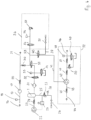
- the compressed air line 23 opens into the water line 17 and is secured against this by a non-return valve 30 . It prevents water from entering the compressed air line 23 from the water line 17 .
- Downstream of the compressed air tank 1 is a filter 31 which filters out impurities from the compressed air flowing through the compressed air line 23 .
- a pressure regulator 32 In the compressed air line 23 sits behind the filter 31, a pressure regulator 32, with which the passage of compressed air to the water line 17 can be controlled. In 4 the pressure regulator 32 is in its blocking position, so that no compressed air can get into the water line 17 .
- a pressure sensor 33 Downstream of the pressure regulator 32 is a pressure sensor 33 which switches the pressure regulator 34 on.
- the pressure sensor 33 is designed for a pressure range of up to approximately 10 bar. Excessive pressure in the compressed air line can be reduced with the pressure regulator 34 .
- the pressure regulator 34 In 4 the pressure regulator 34 is in its blocking position, so that when the compressed air line 23 is released by the pressure regulator 32, the pressure is not reduced. If the pressure of the compressed air rises above a predetermined value, the pressure regulator 34 is adjusted to its open position, so that an excessive pressure in the compressed air line 23 can be reduced accordingly.
- the pressure regulator 34 is switched automatically via a corresponding control, so that it is ensured that when the pressure regulator 32 is open, the compressed air is introduced into the water line 17 at the prescribed pressure.
- a switching valve 35 which is advantageously a 3/2-way valve. It is in the representation according to 4 in open position.
- the pressure regulator 32 is set to the open position, so that the compressed air reaches the water line 17 via the line 23 .
- the connection of the compressed air line 23 to the water line 17 is located in the area between the check valve 20 and the outlet 21.
- the pressure sensor 33 in conjunction with the pressure regulator 34 ensures that the compressed air reaches the water line 17 at the required pressure.
- the pressurized air can be fed into the water line 17 continuously or in pulses, depending on the flushing process desired.
- the device also offers the possibility of examining the lines of the installation by means of a pressure test with air.
- Module 36 is provided for this ( 4 ). It has a compressed air line 39 which is provided with a compressed air connection 37 .
- the compressed air line 39 can be connected to an air supply line 41 via a directional control valve 40 .
- the directional valve 40 is a 3/2-way valve. With the directional valve 40, the device can be switched from a pressure test with air to a pressure test with water.
- the air supply pipe 41 is connected to a pump 42 which is a hydropneumatic pump with which water can be pumped from a water pipe 43 .
- the water line 43 has a connection 44 via which the device can be connected to the water supply.
- the water line 43 is secured by a check valve 45 against the water network.
- the water is fed to an outlet 46, via which the device can be connected to the lines of the installation to be tested, for example via a pressure hose.
- the output 46 is preceded by a pressure sensor 48 which switches a pressure regulator 49 .
- the pressure sensor 48 is designed for a pressure range of up to about 40 bar, for example. With the pressure transducer 48 can the pressure of the water in the water line 43 can be maintained at a predetermined value. If the water pressure is too high, then the pressure regulator 49 is switched so that the water pressure can be reduced via the now open pressure regulator 49 . As soon as the water pressure reaches the required value intended for the test, the pressure regulator 49 is returned to its in 4 shown blocking position adjusted.
- the check valve 47 is followed by a safety valve 50, which opens when a maximum pressure in the water line 43 is exceeded, so that the pressure can be reduced.
- the safety valve 50 is shown in the closed position.
- a check valve 51 which closes in the direction of the safety valve 50 .
- the water pipe 43 with the hydropneumatic pump 42, the pressure sensor 48, the pressure regulator 49 and the safety valve 50 form a module 52 with which a water pressure test of the pipes of the installation can be carried out.
- the air supply line 41 is connected to the hydropneumatic pump 42 and can be connected to a compressed air line 53 via the directional control valve 40 . It is connected to the directional control valve 35 and has a directional control valve 54, which is advantageously a solenoid valve.
- the compressed air line 53 is secured by a safety valve 55, which opens when a predetermined pressure is exceeded.
- the safety valve 55 is designed in such a way that it opens when a pressure of 1.8 bar is exceeded. Of course, this pressure value is not to be considered as limiting.
- a pressure sensor 56 is located in the compressed air line 53 between the safety valve 55 and the directional control valve 54 and is designed for a pressure range of up to approximately 200 mbar in the exemplary embodiment.
- the directional valve 54, the safety valve 55, the pressure sensor 56 and the compressed air connection 37 are part of the module 36, with which a pressure test with air of the line system of the installation can be carried out.
- the module 36 is designed in such a way that it can be used for a pressure test with air at 150 mbar or at 3 bar.
- the compressed air connection 37 can also be used to inflate containers of all kinds (air pump).
- the pressure can be set via the pressure sensor 33 and the pressure regulator 32.
- the air supply line 41 is connected to the compressed air line 53 in the area between the directional control valve 35 and the directional control valve 54 .
- the directional control valve 54 In the position after 4 the directional control valve 54 is in its closed position.
- the directional control valve 40 is switched in such a way that the compressed air line 39 is connected to the compressed air line 53 .
- the directional control valve 35 is switched in such a way that the compressed air line 53 is not connected to the compressed air line 23 .
- the air supply line 41 is blocked off from the compressed air line 53 by the directional control valve 40 . Since the pressure regulator 32 is in the blocked position, the compressed air line 23 is blocked from the water line 17 . In this switching state, the device is connected to the water mains via the water connection 16.
- the line system of the installation to be flushed is connected to the outlet 21 via a hose.
- the water line 17 is released, so that the water from the water network enters the line system of the installation, which is thereby flushed through to the required extent.
- the line system can in particular be a drinking water or heating system.
- the flushing process must be flushed with drinking water as soon as possible after installation and a pressure test and immediately before commissioning (EN 806-4).
- the test regulations stipulate that at regular intervals (up to 7 days) if the pipe system is not put into operation immediately after commissioning. With the device, it is easy and reliable to carry out this necessary rinsing process.
- the disinfectant is in a container that is connected to the outlet 37.
- a T-coupling piece can be connected to the outlet 37 for this purpose.
- the connection for the compressed air line 39 is in the T-foot of the T-piece.
- the disinfection container is connected to the T-foot.
- the T-bar is connected at one end to the outlet 37 and at the other end to the plumbing of the installation.
- the directional valve 35 is from the in 4 The position shown is switched so that the compressed air coming from the compressed air tank 1 reaches the connection 37 via the compressed air line 23, the switched directional control valve 35, the compressed air line 53, the directional control valve 40 and the compressed air line 39.
- the device can also be used to carry out a pressure and leak test of the installation's drinking water and heating systems using compressed air.
- a pressure and leak test is in the ZVSHK leaflet T 82-2011 "Leak testing of drinking water installations with compressed air, inert gas or water".
- a preliminary test with 150 mbar be carried out first. Certain test times are prescribed for this preliminary test.
- a load test (main test) in which the pressure is increased to 3 bar, for example.
- This test method can also be carried out in a simple manner with the device.
- a compressed air hose is connected to the compressed air connection 37, which in turn is connected to the line system of the installation.
- the directional valve 35 is from the position according to 4 switched so that the compressed air from the compressor 22 or from the compressed air tank 1 via the line 23 and the switched directional control valve 35 and the directional control valve 40, the position according to 4 occupies, enters the compressed air line 39.
- the directional control valve 54 is moved from the position according to 4 switched.
- the required low pressure is detected by the pressure sensor 56 and the pressure controller 34 is regulated accordingly.
- the pressure regulator 34 ensures that when this pre-test pressure is exceeded, the pressure is reduced accordingly.
- the downstream safety valve 55 protects the pressure sensor 56.
- the directional control valve 54 is switched to the in 4 shown position switched back.
- the necessary higher test pressure up to eg 3 bar
- the pressure sensor 33 is designed for this pressure range, so that it is ensured that the compressed air reaches the line system via the compressed air outlet 37 at the required test pressure. If the test pressure is exceeded, the pressure is reduced accordingly via the pressure regulator 34 .
- the device can also be used to carry out a pressure and leak test on drinking water.
- the corresponding regulations for this can be found in EN 806-4:2010 and ZVSHK leaflet T 82-2011. je
- different test conditions are provided.
- connection 44 is used to connect to the water network.
- the hydropneumatic pump 42 conveys the water via the water pipe 43 to the outlet 46, via which the device is connected to the pipe system of the installation.
- the directional control valves 35 and 40 are in accordance with the position 4 switched over, so that the compressed air from the compressor 22 or from the compressed air tank 1 via the compressed air lines 23, 53 enters the air supply line 41.
- the hydropneumatic pump 42 is accordingly supplied with the necessary compressed air to generate the necessary water pressure.
- test pressure required for the pressure test with water is thus available at the outlet 46 .
- the pressure sensor 48 in conjunction with the pressure regulator 49 ensure that when the test pressure is exceeded by opening the pressure regulator 49, the pressure is reduced accordingly.
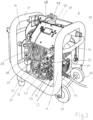
- the individual components of the device are arranged on both sides of the partition wall 11, resulting in a very compact and low construction of the device.
- the compressor 22, the pressure reducer 27, the manometer 28 and the pressure switch 29 are arranged on one side of the partition wall 11 ( 1 ).
- On the opposite side of the partition wall 11 are the pressure regulators 32, 34, 49 and the directional control valves 35, 40.
- the pressure regulator and directional control valve are arranged one above the other to save space ( 2 ). In this case, these components are arranged adjacent to the frame part 6 .
- the hydropneumatic pump 42, the filter 31, the pressure sensor 48 and the control panel 58 are also located on this side of the partition wall 11.
- the weight is evenly distributed, so that the device can be driven comfortably by the user.
- Corresponding wheels or rollers 60 are mounted on the base frame 1 in the area of the frame parts 4, 6 so that they can rotate freely.
- the frame parts 2, 3 In the area of the opposite frame parts 5, 7, the frame parts 2, 3 have feet 61 on the underside, which give the device a secure footing while working. So that the device can be moved comfortably, it is provided with a swivel bracket 62 ( 1 and 3 ), whose mutually parallel legs 63, 64 are mounted at the free end so as to be freely pivotable about horizontal axes 67.
- the legs 63, 64 are directed downwards from the pivot axes 65, so that they take up little space.
- the bracket 62 is grasped at the web 66, which connects the two legs 63, 64 to one another. It is advantageously formed in one piece with the legs 63, 64.
- the bracket 62 is pivoted up about the horizontal pivot axes 65 on the web 66 .
- the pivot axes 65 are mounted in a U-shaped bearing piece 67 which is attached to the outside of the frame parts 5, 7 is.
- the bearing pieces 67 are provided in such a way that the legs 63, 64 strike the webs 68 of the bearing pieces 67 when the bracket 62 is pivoted up. As a result, the pivoting path of the bracket 62 is limited in a simple manner.
- the bearing pieces 67 are located approximately at the level of the connection areas of the cross strut 15 to the two frame parts 5, 7.
- the two cross struts 14, 15 are on the frame parts 4, 6; 5, 7 attached so that they protrude slightly beyond this to the outside. They therefore offer impact protection if the device should hit a wall, a table and the like while driving, for example.
- the cross braces 14, 15 thereby protect the base frame 1 and/or the components of the device.
- the base frame 1 is designed in such a way that it can accommodate the quantities of compressed air required for testing purposes.
- the capacity of the base frame 1 is chosen so that it can hold 5 liters of compressed air.
- the base frame 1 can also be designed for a larger or smaller amount of compressed air. Since no separate compressed air tank is required for the compressed air tank, the described design of the base frame 1 as a compressed air tank contributes particularly to the compact design of the device, which has a low center of gravity due to the described design.
Landscapes
- Engineering & Computer Science (AREA)
- Mechanical Engineering (AREA)
- General Engineering & Computer Science (AREA)
- Examining Or Testing Airtightness (AREA)
- Filling Or Discharging Of Gas Storage Vessels (AREA)
- Cleaning In General (AREA)
- Investigating Strength Of Materials By Application Of Mechanical Stress (AREA)
Claims (12)
- Appareil de rinçage et de contrôle de la pression et de l'étanchéité de conduites de systèmes d'eau potable et/ou de chauffage, pourvu d'un châssis de base (1), l'appareil comportant au moins une conduite d'eau (17, 43), dotée d'un raccordement (16, 44) sur le réseau d'eau et d'au moins une sortie (21, 46) destinée à être raccordée sur les conduites du système d'eau potable et/ou de chauffage, dans la conduite d'eau (17) débouchant au moins une conduite d'air comprimé (23) qui est sécurisée à l'encontre de la conduite d'eau (17) par un clapet antiretour (30) et dans laquelle se trouve une soupape de commutation (35), de préférence une soupape à 3/2 voies, à l'aide de laquelle l'accès de l'air comprimé vers la conduite d'eau (17) est sélectivement susceptible d'être bloqué et libéré, et un compresseur (22), derrière lequel se trouve un régulateur de pression (32), qui permet de contrôler le passage de l'air comprimé vers la conduite d'eau (17) et en aval duquel se trouve un capteur de pression (33), qui commute un régulateur de pression (34), lequel est commuté automatiquement par une commande, et dans la conduite d'eau (17, 43) se trouvant un clapet antiretour (20, 45) qui sécurise la conduite d'eau (17, 43) à l'encontre du raccordement (16, 44) sur le réseau d'eau, dans laquelle une autre conduite d'air comprimé (53), protégée par une soupape de sécurité (55), est raccordée à la soupape de commutation (35), laquelle conduite d'air comprimé est pourvue d'un raccord (37) pour les conduites d'essai de pression à l'air et dans laquelle est logée une autre soupape de commutation (40), qui est avantageusement un commutateur pour l'essai de pression à l'air ou au liquide, dans laquelle un autre capteur de pression (56) est logé entre la soupape de sécurité (55) et une soupape de commande directionnelle (54) dans l'autre conduite d'air comprimé (53).
- Appareil selon la revendication 1,
caractérisé en ce que dans la conduite d'air comprimé (23) se trouve au moins un compresseur (22). - Appareil selon la revendication 1 ou 2,
caractérisé en ce que la soupape de commutation (40) supplémentaire est une soupape à 3/2 voies. - Appareil selon l'une quelconque des revendications 1 ou 3,
caractérisé en ce que sur la soupape de commutation (40) supplémentaire est raccordé par l'intermédiaire d'une conduite d'alimentation d'air (41) un générateur de pression (42) pour le milieu liquide. - Appareil selon l'une quelconque des revendications 1 à 4,
caractérisé en ce que le réservoir d'air comprimé (1) est un cadre de base du châssis de base. - Appareil selon la revendication 5,
caractérisé en ce que le cadre de base (1) est conçu de manière symétrique par rapport à l'axe longitudinal du châssis de base. - Appareil selon la revendication 5 ou 6,
caractérisé en ce que le cadre de base (1) comporte deux parties de cadres (4, 6, 8 ; 5, 7, 9) en forme de U, qui sont placées debout et qui passent l'une dans l'autre par deux parties de cadre (2, 3) horizontales. - Appareil selon la revendication 7,
caractérisé en ce qu'aux les parties de cadre (2, 3) horizontales est fixé un fond inférieur (10). - Appareil selon la revendication 8,
caractérisé en ce que sur le fond inférieur (10) est placée une cloison de séparation (11) placée debout. - Appareil selon l'une quelconque des revendications 1 à 9,
caractérisé en ce que les soupapes de commutation (35, 40) sont raccordées sur un système de commande. - Appareil selon la revendication 10,
caractérisé en ce que l'appareil est muni d'au moins un pupitre de commande (58) qui est muni d'éléments de saisie, destinés à la saisie de données et/ou d'instructions dans le système de commande - Appareil selon l'une quelconque des revendications 1 à 11,
caractérisé en ce que sur le réservoir d'air comprimé (1) est raccordé un raccord (26) pour un outil fonctionnant par air comprimé.
Applications Claiming Priority (1)
| Application Number | Priority Date | Filing Date | Title |
|---|---|---|---|
| DE201310010832 DE102013010832A1 (de) | 2013-06-21 | 2013-06-21 | Gerät zum Spülen und/oder zur Druck - und Dichtheitsprüfung von Leitungen, insbesondere von Trinkwasser- und/oder Heizungssystemen |
Publications (3)
| Publication Number | Publication Date |
|---|---|
| EP2816231A1 EP2816231A1 (fr) | 2014-12-24 |
| EP2816231B1 EP2816231B1 (fr) | 2020-08-26 |
| EP2816231B2 true EP2816231B2 (fr) | 2023-05-10 |
Family
ID=50846747
Family Applications (1)
| Application Number | Title | Priority Date | Filing Date |
|---|---|---|---|
| EP14001893.8A Active EP2816231B2 (fr) | 2013-06-21 | 2014-05-31 | Appareil de rinçage et/ou de contrôle de la pression et de l'étanchéité de conduites, notamment de systèmes d'eau potable et/ou de chauffage |
Country Status (3)
| Country | Link |
|---|---|
| EP (1) | EP2816231B2 (fr) |
| DE (1) | DE102013010832A1 (fr) |
| ES (1) | ES2831755T5 (fr) |
Families Citing this family (1)
| Publication number | Priority date | Publication date | Assignee | Title |
|---|---|---|---|---|
| DE102013010832A1 (de) † | 2013-06-21 | 2014-12-24 | Rems Gmbh & Co Kg | Gerät zum Spülen und/oder zur Druck - und Dichtheitsprüfung von Leitungen, insbesondere von Trinkwasser- und/oder Heizungssystemen |
Citations (6)
| Publication number | Priority date | Publication date | Assignee | Title |
|---|---|---|---|---|
| US4662551A (en) † | 1985-11-12 | 1987-05-05 | Corona Clipper Company | Back-pack power supply for pneumatic hand tools |
| CH662070A5 (en) † | 1984-08-16 | 1987-09-15 | Fischer Ag Georg | Process and device for flushing and cleaning a pipeline |
| EP0244811A2 (fr) † | 1986-05-05 | 1987-11-11 | Grünbeck Wasseraufbereitung GmbH | Installation pour le nettoyage des tuyauteries |
| US5440918A (en) † | 1994-04-18 | 1995-08-15 | Oster; Earl H. | Portable piping-and-pump-system testing apparatus |
| US20050241677A1 (en) † | 2004-05-03 | 2005-11-03 | The Boeing Company | Combined pressure test and clean apparatus |
| EP2816231A1 (fr) † | 2013-06-21 | 2014-12-24 | REMS GmbH & Co KG | Appareil de rinçage et/ou de contrôle de la pression et de l'étanchéité de conduites, notamment de systèmes d'eau potable et/ou de chauffage |
Family Cites Families (4)
| Publication number | Priority date | Publication date | Assignee | Title |
|---|---|---|---|---|
| US20050145270A1 (en) * | 2003-12-31 | 2005-07-07 | Ray R. K. | Pressure washer with injector |
| US20080219860A1 (en) * | 2007-03-08 | 2008-09-11 | Alltrade Tools Llc | Protection system for air compressor assembly |
| CA2639600A1 (fr) * | 2008-09-15 | 2010-03-15 | Town of Markham | Appareil et methode d'essai de soupapes et clapets |
| WO2012177645A2 (fr) * | 2011-06-20 | 2012-12-27 | Graco Minnesota Inc. | Ensemble d'adaptateur de bec verseur pour système de pompage |
-
2013
- 2013-06-21 DE DE201310010832 patent/DE102013010832A1/de active Pending
-
2014
- 2014-05-31 EP EP14001893.8A patent/EP2816231B2/fr active Active
- 2014-05-31 ES ES14001893T patent/ES2831755T5/es active Active
Patent Citations (6)
| Publication number | Priority date | Publication date | Assignee | Title |
|---|---|---|---|---|
| CH662070A5 (en) † | 1984-08-16 | 1987-09-15 | Fischer Ag Georg | Process and device for flushing and cleaning a pipeline |
| US4662551A (en) † | 1985-11-12 | 1987-05-05 | Corona Clipper Company | Back-pack power supply for pneumatic hand tools |
| EP0244811A2 (fr) † | 1986-05-05 | 1987-11-11 | Grünbeck Wasseraufbereitung GmbH | Installation pour le nettoyage des tuyauteries |
| US5440918A (en) † | 1994-04-18 | 1995-08-15 | Oster; Earl H. | Portable piping-and-pump-system testing apparatus |
| US20050241677A1 (en) † | 2004-05-03 | 2005-11-03 | The Boeing Company | Combined pressure test and clean apparatus |
| EP2816231A1 (fr) † | 2013-06-21 | 2014-12-24 | REMS GmbH & Co KG | Appareil de rinçage et/ou de contrôle de la pression et de l'étanchéité de conduites, notamment de systèmes d'eau potable et/ou de chauffage |
Non-Patent Citations (2)
| Title |
|---|
| Deutsche Norm DIN EN 806-4, in Kraft seit September 2010 † |
| Technische Regeln Druckbehälter (TRB4O3). Veröffentlicht im Januar 1984, BArbBl. 1/1984 S. 45 † |
Also Published As
| Publication number | Publication date |
|---|---|
| ES2831755T3 (es) | 2021-06-09 |
| DE102013010832A1 (de) | 2014-12-24 |
| EP2816231B1 (fr) | 2020-08-26 |
| ES2831755T5 (es) | 2023-09-28 |
| EP2816231A1 (fr) | 2014-12-24 |
Similar Documents
| Publication | Publication Date | Title |
|---|---|---|
| DE3722549C2 (fr) | ||
| EP1855061A2 (fr) | Ensemble d'armature destiné au remplissage de systèmes de chauffage | |
| EP2816231B2 (fr) | Appareil de rinçage et/ou de contrôle de la pression et de l'étanchéité de conduites, notamment de systèmes d'eau potable et/ou de chauffage | |
| AT514205B1 (de) | Verfahren zum Dämpfen von Druckpulsationen | |
| DE102012109433B4 (de) | Verfahren zur Druck- und Unterdruckprüfung von Rohrleitungssystemen auf Dichtigkeit | |
| EP1073531B1 (fr) | Dispositif et procede de lavage alterne sous pression | |
| DE10105393C1 (de) | Sicherheitsgruppe zur Absicherung eines geschlossenen Trinkwassererwärmers | |
| DE60222586T2 (de) | Verfahren und vorrichtung zur entfernung von restwasser | |
| EP0123086B1 (fr) | Adsorbeur | |
| DE19528160A1 (de) | Rohr- und Schlauchinstallation an und in Mediensäulen für die Behandlung von Körperflüssigkeiten, insbesondere für ein Dialysegerät | |
| EP1758691A1 (fr) | Procede et appareil pour le changement de phase dans un isolateur | |
| AT414034B (de) | Einrichtung zum dämpfen von druckstössen und abpuffern von in einer flüssigkeitsleitung strömenden flüssigkeiten | |
| DE102008016933A1 (de) | Verfahren und Vorrichtung zum Befüllen eines Löschmittelbehälters eines Feuerlöschers mit einem fließfähigen, unter Druck stehenden Löschmittel | |
| DE102006041677A1 (de) | System zur Reinigung von medienführenden Wegen in einer Beschichtungsanlage | |
| DE202011108088U1 (de) | Beregnungsanlage | |
| EP2660397A1 (fr) | Installation d'injection d'eau pour l'appareil d'extinction d'incendie | |
| DE29808529U1 (de) | Installationsmodul | |
| EP1296123B1 (fr) | Installation transmetteur montée sur un conduit d'une installation de traitement | |
| EP3650829A1 (fr) | Installation d'essai permettant de mettre en uvre un essai d'exposition au feu sur une vanne de courant d'eau | |
| DE3925875A1 (de) | Kompressoreinrichtung | |
| DE136702C (fr) | ||
| WO2010086423A1 (fr) | Aérateur | |
| DE102017105419A1 (de) | Vorrichtung zur Befüllung von Tanks mit Zwischenbehälter | |
| DE864505C (de) | Einrichtung zur Ultraviolett-Behandlung von Fluessigkeiten | |
| DE202017102605U1 (de) | Ventilkombination |
Legal Events
| Date | Code | Title | Description |
|---|---|---|---|
| PUAI | Public reference made under article 153(3) epc to a published international application that has entered the european phase |
Free format text: ORIGINAL CODE: 0009012 |
|
| 17P | Request for examination filed |
Effective date: 20140531 |
|
| AK | Designated contracting states |
Kind code of ref document: A1 Designated state(s): AL AT BE BG CH CY CZ DE DK EE ES FI FR GB GR HR HU IE IS IT LI LT LU LV MC MK MT NL NO PL PT RO RS SE SI SK SM TR |
|
| AX | Request for extension of the european patent |
Extension state: BA ME |
|
| R17P | Request for examination filed (corrected) |
Effective date: 20150624 |
|
| RBV | Designated contracting states (corrected) |
Designated state(s): AL AT BE BG CH CY CZ DE DK EE ES FI FR GB GR HR HU IE IS IT LI LT LU LV MC MK MT NL NO PL PT RO RS SE SI SK SM TR |
|
| STAA | Information on the status of an ep patent application or granted ep patent |
Free format text: STATUS: EXAMINATION IS IN PROGRESS |
|
| 17Q | First examination report despatched |
Effective date: 20180629 |
|
| GRAP | Despatch of communication of intention to grant a patent |
Free format text: ORIGINAL CODE: EPIDOSNIGR1 |
|
| STAA | Information on the status of an ep patent application or granted ep patent |
Free format text: STATUS: GRANT OF PATENT IS INTENDED |
|
| INTG | Intention to grant announced |
Effective date: 20200313 |
|
| GRAS | Grant fee paid |
Free format text: ORIGINAL CODE: EPIDOSNIGR3 |
|
| GRAA | (expected) grant |
Free format text: ORIGINAL CODE: 0009210 |
|
| STAA | Information on the status of an ep patent application or granted ep patent |
Free format text: STATUS: THE PATENT HAS BEEN GRANTED |
|
| AK | Designated contracting states |
Kind code of ref document: B1 Designated state(s): AL AT BE BG CH CY CZ DE DK EE ES FI FR GB GR HR HU IE IS IT LI LT LU LV MC MK MT NL NO PL PT RO RS SE SI SK SM TR |
|
| REG | Reference to a national code |
Ref country code: GB Ref legal event code: FG4D Free format text: NOT ENGLISH |
|
| REG | Reference to a national code |
Ref country code: CH Ref legal event code: EP |
|
| REG | Reference to a national code |
Ref country code: DE Ref legal event code: R096 Ref document number: 502014014659 Country of ref document: DE |
|
| REG | Reference to a national code |
Ref country code: AT Ref legal event code: REF Ref document number: 1306622 Country of ref document: AT Kind code of ref document: T Effective date: 20200915 |
|
| REG | Reference to a national code |
Ref country code: IE Ref legal event code: FG4D Free format text: LANGUAGE OF EP DOCUMENT: GERMAN |
|
| REG | Reference to a national code |
Ref country code: LT Ref legal event code: MG4D |
|
| PG25 | Lapsed in a contracting state [announced via postgrant information from national office to epo] |
Ref country code: NO Free format text: LAPSE BECAUSE OF FAILURE TO SUBMIT A TRANSLATION OF THE DESCRIPTION OR TO PAY THE FEE WITHIN THE PRESCRIBED TIME-LIMIT Effective date: 20201126 Ref country code: PT Free format text: LAPSE BECAUSE OF FAILURE TO SUBMIT A TRANSLATION OF THE DESCRIPTION OR TO PAY THE FEE WITHIN THE PRESCRIBED TIME-LIMIT Effective date: 20201228 Ref country code: BG Free format text: LAPSE BECAUSE OF FAILURE TO SUBMIT A TRANSLATION OF THE DESCRIPTION OR TO PAY THE FEE WITHIN THE PRESCRIBED TIME-LIMIT Effective date: 20201126 Ref country code: LT Free format text: LAPSE BECAUSE OF FAILURE TO SUBMIT A TRANSLATION OF THE DESCRIPTION OR TO PAY THE FEE WITHIN THE PRESCRIBED TIME-LIMIT Effective date: 20200826 Ref country code: FI Free format text: LAPSE BECAUSE OF FAILURE TO SUBMIT A TRANSLATION OF THE DESCRIPTION OR TO PAY THE FEE WITHIN THE PRESCRIBED TIME-LIMIT Effective date: 20200826 Ref country code: HR Free format text: LAPSE BECAUSE OF FAILURE TO SUBMIT A TRANSLATION OF THE DESCRIPTION OR TO PAY THE FEE WITHIN THE PRESCRIBED TIME-LIMIT Effective date: 20200826 Ref country code: SE Free format text: LAPSE BECAUSE OF FAILURE TO SUBMIT A TRANSLATION OF THE DESCRIPTION OR TO PAY THE FEE WITHIN THE PRESCRIBED TIME-LIMIT Effective date: 20200826 |
|
| REG | Reference to a national code |
Ref country code: NL Ref legal event code: MP Effective date: 20200826 |
|
| PG25 | Lapsed in a contracting state [announced via postgrant information from national office to epo] |
Ref country code: LV Free format text: LAPSE BECAUSE OF FAILURE TO SUBMIT A TRANSLATION OF THE DESCRIPTION OR TO PAY THE FEE WITHIN THE PRESCRIBED TIME-LIMIT Effective date: 20200826 Ref country code: RS Free format text: LAPSE BECAUSE OF FAILURE TO SUBMIT A TRANSLATION OF THE DESCRIPTION OR TO PAY THE FEE WITHIN THE PRESCRIBED TIME-LIMIT Effective date: 20200826 Ref country code: PL Free format text: LAPSE BECAUSE OF FAILURE TO SUBMIT A TRANSLATION OF THE DESCRIPTION OR TO PAY THE FEE WITHIN THE PRESCRIBED TIME-LIMIT Effective date: 20200826 Ref country code: NL Free format text: LAPSE BECAUSE OF FAILURE TO SUBMIT A TRANSLATION OF THE DESCRIPTION OR TO PAY THE FEE WITHIN THE PRESCRIBED TIME-LIMIT Effective date: 20200826 Ref country code: IS Free format text: LAPSE BECAUSE OF FAILURE TO SUBMIT A TRANSLATION OF THE DESCRIPTION OR TO PAY THE FEE WITHIN THE PRESCRIBED TIME-LIMIT Effective date: 20201226 |
|
| PG25 | Lapsed in a contracting state [announced via postgrant information from national office to epo] |
Ref country code: RO Free format text: LAPSE BECAUSE OF FAILURE TO SUBMIT A TRANSLATION OF THE DESCRIPTION OR TO PAY THE FEE WITHIN THE PRESCRIBED TIME-LIMIT Effective date: 20200826 Ref country code: SM Free format text: LAPSE BECAUSE OF FAILURE TO SUBMIT A TRANSLATION OF THE DESCRIPTION OR TO PAY THE FEE WITHIN THE PRESCRIBED TIME-LIMIT Effective date: 20200826 Ref country code: DK Free format text: LAPSE BECAUSE OF FAILURE TO SUBMIT A TRANSLATION OF THE DESCRIPTION OR TO PAY THE FEE WITHIN THE PRESCRIBED TIME-LIMIT Effective date: 20200826 Ref country code: CZ Free format text: LAPSE BECAUSE OF FAILURE TO SUBMIT A TRANSLATION OF THE DESCRIPTION OR TO PAY THE FEE WITHIN THE PRESCRIBED TIME-LIMIT Effective date: 20200826 Ref country code: EE Free format text: LAPSE BECAUSE OF FAILURE TO SUBMIT A TRANSLATION OF THE DESCRIPTION OR TO PAY THE FEE WITHIN THE PRESCRIBED TIME-LIMIT Effective date: 20200826 |
|
| REG | Reference to a national code |
Ref country code: DE Ref legal event code: R026 Ref document number: 502014014659 Country of ref document: DE |
|
| PLBI | Opposition filed |
Free format text: ORIGINAL CODE: 0009260 |
|
| PG25 | Lapsed in a contracting state [announced via postgrant information from national office to epo] |
Ref country code: AL Free format text: LAPSE BECAUSE OF FAILURE TO SUBMIT A TRANSLATION OF THE DESCRIPTION OR TO PAY THE FEE WITHIN THE PRESCRIBED TIME-LIMIT Effective date: 20200826 |
|
| PLAX | Notice of opposition and request to file observation + time limit sent |
Free format text: ORIGINAL CODE: EPIDOSNOBS2 |
|
| REG | Reference to a national code |
Ref country code: ES Ref legal event code: FG2A Ref document number: 2831755 Country of ref document: ES Kind code of ref document: T3 Effective date: 20210609 |
|
| 26 | Opposition filed |
Opponent name: CARELA GMBH Effective date: 20210526 |
|
| PG25 | Lapsed in a contracting state [announced via postgrant information from national office to epo] |
Ref country code: SK Free format text: LAPSE BECAUSE OF FAILURE TO SUBMIT A TRANSLATION OF THE DESCRIPTION OR TO PAY THE FEE WITHIN THE PRESCRIBED TIME-LIMIT Effective date: 20200826 |
|
| PG25 | Lapsed in a contracting state [announced via postgrant information from national office to epo] |
Ref country code: SI Free format text: LAPSE BECAUSE OF FAILURE TO SUBMIT A TRANSLATION OF THE DESCRIPTION OR TO PAY THE FEE WITHIN THE PRESCRIBED TIME-LIMIT Effective date: 20200826 |
|
| PLBB | Reply of patent proprietor to notice(s) of opposition received |
Free format text: ORIGINAL CODE: EPIDOSNOBS3 |
|
| REG | Reference to a national code |
Ref country code: CH Ref legal event code: PL |
|
| GBPC | Gb: european patent ceased through non-payment of renewal fee |
Effective date: 20210531 |
|
| PG25 | Lapsed in a contracting state [announced via postgrant information from national office to epo] |
Ref country code: LU Free format text: LAPSE BECAUSE OF NON-PAYMENT OF DUE FEES Effective date: 20210531 Ref country code: LI Free format text: LAPSE BECAUSE OF NON-PAYMENT OF DUE FEES Effective date: 20210531 Ref country code: MC Free format text: LAPSE BECAUSE OF FAILURE TO SUBMIT A TRANSLATION OF THE DESCRIPTION OR TO PAY THE FEE WITHIN THE PRESCRIBED TIME-LIMIT Effective date: 20200826 Ref country code: CH Free format text: LAPSE BECAUSE OF NON-PAYMENT OF DUE FEES Effective date: 20210531 |
|
| REG | Reference to a national code |
Ref country code: BE Ref legal event code: MM Effective date: 20210531 |
|
| PG25 | Lapsed in a contracting state [announced via postgrant information from national office to epo] |
Ref country code: IE Free format text: LAPSE BECAUSE OF NON-PAYMENT OF DUE FEES Effective date: 20210531 Ref country code: GB Free format text: LAPSE BECAUSE OF NON-PAYMENT OF DUE FEES Effective date: 20210531 |
|
| REG | Reference to a national code |
Ref country code: AT Ref legal event code: MM01 Ref document number: 1306622 Country of ref document: AT Kind code of ref document: T Effective date: 20210531 |
|
| PG25 | Lapsed in a contracting state [announced via postgrant information from national office to epo] |
Ref country code: BE Free format text: LAPSE BECAUSE OF NON-PAYMENT OF DUE FEES Effective date: 20210531 |
|
| PG25 | Lapsed in a contracting state [announced via postgrant information from national office to epo] |
Ref country code: AT Free format text: LAPSE BECAUSE OF NON-PAYMENT OF DUE FEES Effective date: 20210531 |
|
| REG | Reference to a national code |
Ref country code: FR Ref legal event code: PLFP Year of fee payment: 10 |
|
| PUAH | Patent maintained in amended form |
Free format text: ORIGINAL CODE: 0009272 |
|
| STAA | Information on the status of an ep patent application or granted ep patent |
Free format text: STATUS: PATENT MAINTAINED AS AMENDED |
|
| 27A | Patent maintained in amended form |
Effective date: 20230510 |
|
| AK | Designated contracting states |
Kind code of ref document: B2 Designated state(s): AL AT BE BG CH CY CZ DE DK EE ES FI FR GB GR HR HU IE IS IT LI LT LU LV MC MK MT NL NO PL PT RO RS SE SI SK SM TR |
|
| REG | Reference to a national code |
Ref country code: DE Ref legal event code: R102 Ref document number: 502014014659 Country of ref document: DE |
|
| PG25 | Lapsed in a contracting state [announced via postgrant information from national office to epo] |
Ref country code: HU Free format text: LAPSE BECAUSE OF FAILURE TO SUBMIT A TRANSLATION OF THE DESCRIPTION OR TO PAY THE FEE WITHIN THE PRESCRIBED TIME-LIMIT; INVALID AB INITIO Effective date: 20140531 |
|
| PG25 | Lapsed in a contracting state [announced via postgrant information from national office to epo] |
Ref country code: CY Free format text: LAPSE BECAUSE OF FAILURE TO SUBMIT A TRANSLATION OF THE DESCRIPTION OR TO PAY THE FEE WITHIN THE PRESCRIBED TIME-LIMIT Effective date: 20200826 |
|
| PG25 | Lapsed in a contracting state [announced via postgrant information from national office to epo] |
Ref country code: GR Free format text: LAPSE BECAUSE OF FAILURE TO SUBMIT A TRANSLATION OF THE DESCRIPTION OR TO PAY THE FEE WITHIN THE PRESCRIBED TIME-LIMIT Effective date: 20200826 |
|
| REG | Reference to a national code |
Ref country code: ES Ref legal event code: DC2A Ref document number: 2831755 Country of ref document: ES Kind code of ref document: T5 Effective date: 20230928 |
|
| P01 | Opt-out of the competence of the unified patent court (upc) registered |
Effective date: 20231115 |
|
| PG25 | Lapsed in a contracting state [announced via postgrant information from national office to epo] |
Ref country code: MK Free format text: LAPSE BECAUSE OF FAILURE TO SUBMIT A TRANSLATION OF THE DESCRIPTION OR TO PAY THE FEE WITHIN THE PRESCRIBED TIME-LIMIT Effective date: 20200826 |
|
| PG25 | Lapsed in a contracting state [announced via postgrant information from national office to epo] |
Ref country code: TR Free format text: LAPSE BECAUSE OF FAILURE TO SUBMIT A TRANSLATION OF THE DESCRIPTION OR TO PAY THE FEE WITHIN THE PRESCRIBED TIME-LIMIT Effective date: 20200826 |
|
| PG25 | Lapsed in a contracting state [announced via postgrant information from national office to epo] |
Ref country code: MT Free format text: LAPSE BECAUSE OF FAILURE TO SUBMIT A TRANSLATION OF THE DESCRIPTION OR TO PAY THE FEE WITHIN THE PRESCRIBED TIME-LIMIT Effective date: 20200826 |
|
| PGFP | Annual fee paid to national office [announced via postgrant information from national office to epo] |
Ref country code: FR Payment date: 20250328 Year of fee payment: 12 |
|
| PGFP | Annual fee paid to national office [announced via postgrant information from national office to epo] |
Ref country code: ES Payment date: 20250605 Year of fee payment: 12 |
|
| PGFP | Annual fee paid to national office [announced via postgrant information from national office to epo] |
Ref country code: IT Payment date: 20250423 Year of fee payment: 12 |
|
| PGFP | Annual fee paid to national office [announced via postgrant information from national office to epo] |
Ref country code: DE Payment date: 20250729 Year of fee payment: 12 |