EP0245552B1 - Kathetervorrichtung mit Laser - Google Patents
Kathetervorrichtung mit Laser Download PDFInfo
- Publication number
- EP0245552B1 EP0245552B1 EP86303746A EP86303746A EP0245552B1 EP 0245552 B1 EP0245552 B1 EP 0245552B1 EP 86303746 A EP86303746 A EP 86303746A EP 86303746 A EP86303746 A EP 86303746A EP 0245552 B1 EP0245552 B1 EP 0245552B1
- Authority
- EP
- European Patent Office
- Prior art keywords
- laser
- laser beam
- catheter
- energy
- distal tip
- Prior art date
- Legal status (The legal status is an assumption and is not a legal conclusion. Google has not performed a legal analysis and makes no representation as to the accuracy of the status listed.)
- Expired
Links
Images

Classifications
-
- B—PERFORMING OPERATIONS; TRANSPORTING
- B23—MACHINE TOOLS; METAL-WORKING NOT OTHERWISE PROVIDED FOR
- B23K—SOLDERING OR UNSOLDERING; WELDING; CLADDING OR PLATING BY SOLDERING OR WELDING; CUTTING BY APPLYING HEAT LOCALLY, e.g. FLAME CUTTING; WORKING BY LASER BEAM
- B23K26/00—Working by laser beam, e.g. welding, cutting or boring
- B23K26/02—Positioning or observing the workpiece, e.g. with respect to the point of impact; Aligning, aiming or focusing the laser beam
- B23K26/03—Observing, e.g. monitoring, the workpiece
- B23K26/032—Observing, e.g. monitoring, the workpiece using optical means
-
- A—HUMAN NECESSITIES
- A61—MEDICAL OR VETERINARY SCIENCE; HYGIENE
- A61B—DIAGNOSIS; SURGERY; IDENTIFICATION
- A61B18/00—Surgical instruments, devices or methods for transferring non-mechanical forms of energy to or from the body
- A61B18/18—Surgical instruments, devices or methods for transferring non-mechanical forms of energy to or from the body by applying electromagnetic radiation, e.g. microwaves
- A61B18/20—Surgical instruments, devices or methods for transferring non-mechanical forms of energy to or from the body by applying electromagnetic radiation, e.g. microwaves using laser
-
- A—HUMAN NECESSITIES
- A61—MEDICAL OR VETERINARY SCIENCE; HYGIENE
- A61B—DIAGNOSIS; SURGERY; IDENTIFICATION
- A61B18/00—Surgical instruments, devices or methods for transferring non-mechanical forms of energy to or from the body
- A61B18/18—Surgical instruments, devices or methods for transferring non-mechanical forms of energy to or from the body by applying electromagnetic radiation, e.g. microwaves
- A61B18/20—Surgical instruments, devices or methods for transferring non-mechanical forms of energy to or from the body by applying electromagnetic radiation, e.g. microwaves using laser
- A61B18/22—Surgical instruments, devices or methods for transferring non-mechanical forms of energy to or from the body by applying electromagnetic radiation, e.g. microwaves using laser the beam being directed along or through a flexible conduit, e.g. an optical fibre; Couplings or hand-pieces therefor
- A61B18/24—Surgical instruments, devices or methods for transferring non-mechanical forms of energy to or from the body by applying electromagnetic radiation, e.g. microwaves using laser the beam being directed along or through a flexible conduit, e.g. an optical fibre; Couplings or hand-pieces therefor with a catheter
- A61B18/245—Surgical instruments, devices or methods for transferring non-mechanical forms of energy to or from the body by applying electromagnetic radiation, e.g. microwaves using laser the beam being directed along or through a flexible conduit, e.g. an optical fibre; Couplings or hand-pieces therefor with a catheter for removing obstructions in blood vessels or calculi
-
- G—PHYSICS
- G02—OPTICS
- G02B—OPTICAL ELEMENTS, SYSTEMS OR APPARATUS
- G02B6/00—Light guides; Structural details of arrangements comprising light guides and other optical elements, e.g. couplings
- G02B6/24—Coupling light guides
- G02B6/42—Coupling light guides with opto-electronic elements
- G02B6/4296—Coupling light guides with opto-electronic elements coupling with sources of high radiant energy, e.g. high power lasers, high temperature light sources
-
- A—HUMAN NECESSITIES
- A61—MEDICAL OR VETERINARY SCIENCE; HYGIENE
- A61B—DIAGNOSIS; SURGERY; IDENTIFICATION
- A61B18/00—Surgical instruments, devices or methods for transferring non-mechanical forms of energy to or from the body
- A61B2018/00636—Sensing and controlling the application of energy
-
- G—PHYSICS
- G02—OPTICS
- G02B—OPTICAL ELEMENTS, SYSTEMS OR APPARATUS
- G02B6/00—Light guides; Structural details of arrangements comprising light guides and other optical elements, e.g. couplings
- G02B6/24—Coupling light guides
- G02B6/42—Coupling light guides with opto-electronic elements
- G02B6/4296—Coupling light guides with opto-electronic elements coupling with sources of high radiant energy, e.g. high power lasers, high temperature light sources
- G02B2006/4297—Coupling light guides with opto-electronic elements coupling with sources of high radiant energy, e.g. high power lasers, high temperature light sources having protection means, e.g. protecting humans against accidental exposure to harmful laser radiation
Definitions
- the present invention relates to a laser catheter device and especially to a laser enhanced transluminal angioplasty catheter system.
- a laser enhanced transluminal angioplasty catheter allows obstructions in blood vessels to be treated with exposure to laser energy to obtain either a partial reduction and/or elimination of the obstruction by means of such exposure.
- An optical fiber is utilized for transmitting the laser beam energy from the generator onto the obstruction located in the zone to be treated.
- the optical fiber can also be utilized for the purpose of providing illumination and optical viewing.
- Laser enhanced transluminal angioplasty catheter devices are considered valuable tools for the treatment of commonly encountered forms of arteriosclerosis and the like.
- Atheroclerosis is among the more commonly encountered forms of arteriosclerosis as it relates to the human heart and circulatory system, which typically has been treated by drugs, angioplasty catheterization, and also through open heart bypass surgical procedures.
- angioplasty catheterization has been found to be a treatment of choice in certain situations.
- Such treatment normally involves initially bringing a balloon-tipped catheter proximate the material forming the obstruction matter in the vessel, with the distal tip catheter normally being forced through the obstruction and the balloon portion is thereafter inflated so as to cause dilation of the obstruction. This procedure is effective in reopening the blood vessel and restoring substantially normal circulation in many cases.
- the catheter is provided with a source of laser energy, and this laser energy is directed to the site along optical fibers.
- dilating catheters are known, having been disclosed in U.S. Patent Nos. 4,040,413; 4,271,839; and 4,299,226.
- Catheter devices including optical fibers are disclosed in U.S. Patent Nos. 3,123,066; 3,136,310; 3,858,577; 4,146,019; and 4,273,019.
- laser enhanced catheters are disclosed in U.S. Patent Nos. 3,467,098; 3,538,919; 3,843,865; and 4,266,548.
- the operator determines and to be reasonably confident that the laser energy being directed to the site is within certain predetermined desirable limits, that is, the energy is known to exceed a certain base or minimum threshold level, while not exceeding a certain upper limit.
- An indication that the laser beam energy is within predetermined limits will enable the procedure to be more reliable, expedient, reproducible, and efficacious.
- the rupture, fracture, or occurrence of damage to the optical fiber may reduce the energy level available at the distal tip of the catheter to such an extent that the procedure would be generally ineffective.
- excessive quantities of laser beam energy available at the distal tip of the catheter may adversely affect the quality of the procedure.
- the preferred embodiment of the present invention utilizes a control system which is interposed along the optical fiber segments which are provided to transmit laser energy from the generator to the distal tip.
- the control system includes an electromechanical shutter and a beam splitter disposed along the beam path.
- An attenuator and a focusing lens are located orthogonal to the energy beam, and a predetermined proportion of the energy is reflected and/or sampled by the beam splitter and directed into the attenuator and focusing lens and onto a first detector.
- the detector is, in turn, coupled to a power level monitor.
- On the catheter side of the beam splitter, and also orthogonal to the beam is an interference filter and a second focusing lens.
- a fluorescent element At the distal tip of the optical fiber there is disposed a fluorescent element.
- fluorescent is intended to be used in a comprehensive sense, such as the response generated in such an element when irradiated with electromagnetic radiation of a given wavelength, with the response being the emission of radiation at a second and longer wavelength.
- One particularly desirable optically reactive device is a sapphire doped to fluoresce when transmitting laser energy. Since the fluorescent energy which is generated by the incident laser energy is at a wavelength significantly different from that of the laser energy, the fluorescent energy is transmitted or reflected back through the optical fiber and onto the catheter facing surface of the beam splitter. The fluorescent energy is then reflected by the catheter facing surface of the beam splitter (dichroic filter) into a focusing lens and thence onto a second detector. The output of the second detector is typically amplified and fed into a threshold detector. The output of the threshold detector is, in turn, coupled to the shutter system as well as to the power supply of the laser generator.
- the system of the present invention permits simultaneous monitoring of the output of the laser generator and the output of the optical fiber.
- an attenuator may be placed in the laser beam path in front of the shutter system. The ratio of the optical fiber output relative to the laser generator output is monitored continuously, and in the event the ratio falls outside of a predetermined range because of a failure of a system component, the entire system may be automatically shut down.
- the present invention allows the feedback of information from the distal tip of the catheter without the need for additional optical fibers or wires to be employed in the catheter. Furthermore, the fiber optic tip at the end of the catheter is properly protected.
- the present invention further allows simultaneous measuring and/or comparing of the laser generator output and the catheter output, with the response time of the feedback system being extremely fast for proper system monitoring. In the event of a malfunction, or if the output deviates from a pre-established or predetermined range, the system may be immediately shut down.
- a fluorescing lens at the distal tip of the optical fiber provides a convenient means for focusing and/or diverging the laser beam energy.
- This lens also provides protection for the tip of the optical fiber.
- Such a lens also makes it possible to monitor the temperature level existing at the distal tip of the optical fiber. Temperature monitoring is an available feature which may be accomplished by intermittent pulsing of the laser along with a measurement of the response time of the incident fluorescent energy.
- the output of the catheter may be monitored relative to the laser output so as to assure operation at the appropriate and desired level.
- EP-A-0069930 discloses in Fig.3 a laser system for a medical application incorporating an optical fiber in which detectors are located at positions remote from the laser energy source and from the laser output position. The detectors monitor an abnormal intensity of laser energy in the fiber e.g. due to optical fiber damage.
- the pre-characterising clause of Claim 1 is based on this disclosure.
- WO-A-8404879 discloses a medical appliance with a head heated by laser energy. Means is provided to detect the heat energy generated by the head. The laser beam passes down an optical fiber and means is provided at the proximal end of the fiber to intercept heat energy, received down the fiber from the head, and direct this energy to a pyrometer so as to measure the temperature of the head. In order to measure the temperature, the laser is deactivated and the intercepting means is moved from a first position, for passing the laser beam, to a second position for directing the heat energy to the pyrometer.
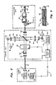
- Figure 1 is a schematic diagram illustrating one embodiment of the present invention, and illustrating simultaneously monitors or measures the output energy from the laser generator as well as the energy received through the transmission system and accordingly available at the distal tip of the catheter;
- Figure 2 is a schematic diagram illustrating the details of the optical unit utilized in the laser enhanced transluminal angioplasty catheter feedback system with the energy feedback being available from the distal tip of the catheter;
- Figure 3 is a fragmentary detail schematic diagram of the distal tip portion only of the catheter assembly.
- the laser enhanced transluminal angioplasty catheter system generally designated 10 ( Figure 1) includes a transluminal angioplasty catheter member 11 having a proximal end 12 and a distal tip end 13, and with the catheter incorporating optical fibers for transmission of laser beam energy therethrough.
- Laser energy is provided from laser head 14, driven by power supply and control 15.
- Laser heads for the generation of laser energy for laser enhanced transluminal angioplasty catheter devices are commercially available, as are power supply and control systems therefor.
- the energy generated at the laser head 14 is transmitted through the wall of the head, along column 16, and into focusing lens 17. Focusing lens 17 directs the energy along the column shown as at 18, and into a first optical fiber segment as at 20.
- Optical fiber 20 is of a convenient length, such as a length of, for example, 10 meters.
- the terminal end 21 of optical fiber segment 20 is designed to pass laser energy along an energy cone as at 22, and into focusing lens 24.
- the beam passing through lens 24 is preferably arranged in a collimated form or parallel path as at 25, and passed into electromechanical dual shutter 26.
- dual shutter 26 permits the beam to pass therethrough, as is indicated in Figure 1, and in the event of any malfunction as will be described hereinafter, electro mechanical dual shutter 26 will close its panel members or vanes 27 and 28 so as to interrupt the passage of laser beam energy therethrough.
- the laser energy exiting shutter 26 is shown in beam form 30, and passes onto beam splitter 31.
- Beam splitter 31 may conveniently be and is preferably a dichroic filter arranged for substantial or maximum transmission of incident laser beam energy.
- the small portion or sample of incident laser energy which is reflected off the surface of beam splitter 31 is indicated as at 32, with the balance of the energy passing through splitter 31 and along beam column shown at 33.
- Beam column 33 passes through focusing lens 34, and into a second segment of optical fibers 35 contained within a lumen formed in laser enhanced transluminal angioplasty catheter 11.
- a fluorescent element for generating radiant energy at a wavelength significantly different from that of the incident laser beam energy.
- the fluorescent means may be a sapphire element containing a dopant which generates fluorescent energy or other radiant energy which is emitted at a wavelength significantly different from that of the incident laser beam energy.
- the sapphire element such as optically reactive or doped sapphire element 37 is, of course, commercially available.
- One such useful dopant is chromium. While a sapphire element containing a dopant has been found to be desirable for use as the material of construction for element 37, it will, of course, be appreciated that other fluorescent substances may be employed as well.
- the material must be highly transmissive to energy within the wavelength of the laser beam, and further it must have the property of generating fluorescent energy or other detectable radiant energy at a wavelength significantly different from that of the incident laser beam energy.
- the radiant energy generated by the fluoresent sapphire element 37 is received by and passed along optical fiber 35, in the direction indicated by arrows 39-39, and onto the catheter facing surface of beam splitter 31.
- the beam splitter (dichroic filter) which in this case, reflects the energy of the wavelength generated by the fluorescent member, passes along the path indicated by arrows 40-40 and ultimately received at the active surface of detector 41. This portion of the apparatus will be described in detail hereinbelow.
- this sample of the overall output energy of the laser passes along beam column 32 through attenuator 43, focusing lens 44, and onto the active surface of radiant energy detector 45.
- a power level indicator as at 46 is in circuit with detector 45, thus providing an indication of the power level of incident laser energy received at the incoming surface of beam splitter 31.
- the output of detector 45 is coupled along line 48 to power supply and power control 15 through the control logic. Detectors such as detector 45, power level indicator 46, and the corresponding input to power supply and control 15 are commercially available.
- an interference filter is shown in the path as at 50, with this filter being adapted for maximun transmission of incident radiation at about 6940 Angstroms. This filter will typically have its peak transmission at the range of maximum generation of the optically reactive member 37.
- the signal generated by detector 41 is passed through a typical pre-amplifier as at 52, for transmission to threshold detector 53.
- the output of threshold detector 53 is normalized with respect to the output laser energy detector and is transmitted to separate logic controls, one being an input to electromechanical dual shutter 26, the other being an input, as at 54, to power supply and control 15. As has been previously indicated, if the normalized output of threshold detector 53 is outside of prescribed and desired limits, the active vanes 27 and 28 of shutter 26 are closed so as to totally interrupt and shut down the transmission of laser beam energy into the catheter 11.
- the laser beam energy passing between focusing lens 24 and focusing lens 34 is, in effect, passing through an evaluation zone for controlling the amount of energy available in the overall system, and also available at the distal tip of the laser enhancing transluminal angioplasty catheter 11.
- Focusing lens 17 provides a means for focusing and directing the beam into the first optical fiber segment as at 20, with segment 20 being typically 10 meters in length.
- the control unit block commences generally at the terminal end of the first optical fiber segment, as also shown in Figure 1.
- Lens 24 is employed to collimate the beam and pass the beam through an attenuator 60.
- Attenuator 60 is utilized to control the amount of the transmitted power through the system.
- Light passing through attenuator 60 passes through electromechanical dual shutter 26 and onto the first surface of beam splitter 31.
- beam splitter 31 is a dichroic filter, with such dichroic filters being, of course, commercially available.
- Dichroic filter 31 is selected so as to provide for maximum transmission of laser light, with only a small percentage being reflected along path 32, as previously set forth in the embodiment of Figure 1.
- Attenuator 43 is employed to control the amount of energy incident to and received upon detector 45.
- the output from detector 45 as indicated previously, is conveniently displayed on power level indicator 46, and ultimately received at the first control input 15C to power supply 15B.
- the laser enhanced transluminal angioplasty catheter 11 as illustrated in Figure 2 is provided with one or more additonal lumens for the transmission of fluids, with the lead-in to the fluid transmitting lumen being shown at 61.
- a protective shield or tubing for catheter 11 is illustrated at 62, with the tubing for the laser enhanced transluminal angioplasty catheter device 11 being preferably formed of an FDA approved material or substance such as, for example, polyethylene or equivalent.
- a metallic or glass sleeve is provided at 63 for receiving optical fibers and the sapphire element.
- additional radiopaque bands such as at 64 and 65, are employed in order to assist in determining and viewing the location of the distal tip portion of laser enhanced transluminal angioplasty catheter 11, and also, in certain instances, may be utilized to locate the position of the distal tip of the optical fiber portions in those systems wherein the optical fibers may extend beyond the distal tip of the catheter sleeve portion, such as beyond polyethylene sleeve portion 11A.
- a buffer sheath may be utilized to encapsulate or coat the outer surface.
- this buffer layer may be one or more films or layers of a polyamide material, and may, in certain instances, contain a UV marker additive.
- Such material may be formed of a compatible polymeric material such as an epoxy material or the like. It may be desirable, in certain instances, to provide this inner film or layer with a UV marker.
- reflected light from optically reactive and responsive element 37 is reflected from surface 31A of beam splitter (dichroic filter) 31 and through interference filter 50 and through focusing lens 67 and into detector element 41.
- the output of threshold detector 53 provides inputs to electromechanical shutter 26 as well as to power supply 15B, such as at the second control input 15D to power supply 15B.
- beam energy from the laser unit may be passed directly onto a beam splitter, with first and second detectors being employed to deliver signals to the control monitor, such as an electromechanical shutter system.
- a focusing lens is provided to carry the laser beam energy into the input of a first optical fiber segment, which terminates through connectors into the control monitor.
- the output from the control monitor is, in turn, delivered into the second optical fiber segment, and thence into the distal tip end of the catheter unit.
Landscapes
- Physics & Mathematics (AREA)
- Health & Medical Sciences (AREA)
- Optics & Photonics (AREA)
- Surgery (AREA)
- Engineering & Computer Science (AREA)
- Life Sciences & Earth Sciences (AREA)
- Heart & Thoracic Surgery (AREA)
- Public Health (AREA)
- Nuclear Medicine, Radiotherapy & Molecular Imaging (AREA)
- Biomedical Technology (AREA)
- Electromagnetism (AREA)
- Medical Informatics (AREA)
- Molecular Biology (AREA)
- Animal Behavior & Ethology (AREA)
- General Health & Medical Sciences (AREA)
- Otolaryngology (AREA)
- Veterinary Medicine (AREA)
- Plasma & Fusion (AREA)
- Mechanical Engineering (AREA)
- General Physics & Mathematics (AREA)
- Vascular Medicine (AREA)
- Laser Surgery Devices (AREA)
- Radiation-Therapy Devices (AREA)
Claims (6)
Priority Applications (4)
| Application Number | Priority Date | Filing Date | Title |
|---|---|---|---|
| AU57036/86A AU576428B2 (en) | 1986-05-16 | 1986-05-02 | Laser catheter feed back system |
| AT86303746T ATE59765T1 (de) | 1986-05-16 | 1986-05-16 | Kathetervorrichtung mit laser. |
| DE8686303746T DE3676815D1 (de) | 1986-05-16 | 1986-05-16 | Kathetervorrichtung mit laser. |
| EP86303746A EP0245552B1 (de) | 1986-05-16 | 1986-05-16 | Kathetervorrichtung mit Laser |
Applications Claiming Priority (1)
| Application Number | Priority Date | Filing Date | Title |
|---|---|---|---|
| EP86303746A EP0245552B1 (de) | 1986-05-16 | 1986-05-16 | Kathetervorrichtung mit Laser |
Publications (2)
| Publication Number | Publication Date |
|---|---|
| EP0245552A1 EP0245552A1 (de) | 1987-11-19 |
| EP0245552B1 true EP0245552B1 (de) | 1991-01-09 |
Family
ID=8196010
Family Applications (1)
| Application Number | Title | Priority Date | Filing Date |
|---|---|---|---|
| EP86303746A Expired EP0245552B1 (de) | 1986-05-16 | 1986-05-16 | Kathetervorrichtung mit Laser |
Country Status (4)
| Country | Link |
|---|---|
| EP (1) | EP0245552B1 (de) |
| AT (1) | ATE59765T1 (de) |
| AU (1) | AU576428B2 (de) |
| DE (1) | DE3676815D1 (de) |
Cited By (1)
| Publication number | Priority date | Publication date | Assignee | Title |
|---|---|---|---|---|
| DE3833361A1 (de) * | 1988-09-30 | 1990-04-12 | Hohla Kristian | Katheder fuer die laser-angioplastie |
Families Citing this family (6)
| Publication number | Priority date | Publication date | Assignee | Title |
|---|---|---|---|---|
| AU600276B2 (en) * | 1985-12-13 | 1990-08-09 | Gv Medical Inc. | Fiber tip monitoring and protection assembly |
| DE3934647C2 (de) * | 1989-10-17 | 1994-05-26 | Deutsche Aerospace | Chirurgisches Laserinstrument |
| GB9106874D0 (en) * | 1991-04-02 | 1991-05-22 | Lumonics Ltd | Optical fibre assembly for a laser system |
| GB9306090D0 (en) * | 1993-03-24 | 1993-05-12 | Bt & D Technologies Ltd | Optical responder |
| DE19906769A1 (de) * | 1998-02-19 | 1999-12-16 | Leica Microsystems | Überlastschutz zur Vermeidung einer Beschädigung optischer Komponenten |
| WO2024147820A1 (en) * | 2023-01-04 | 2024-07-11 | Lumeda Inc. | Pdt light delivery device and dosimetry method |
Family Cites Families (22)
| Publication number | Priority date | Publication date | Assignee | Title |
|---|---|---|---|---|
| US3123066A (en) | 1964-03-03 | brumley | ||
| US3136310A (en) | 1960-01-18 | 1964-06-09 | Bausch & Lomb | Optical catheter |
| US3096767A (en) * | 1961-05-11 | 1963-07-09 | Trg Inc | Photo-cauterizer with coherent light source |
| US3291749A (en) * | 1963-08-14 | 1966-12-13 | Triaxon Inc | Photo-luminescent composition consisting essentially of boric acid and fluorescein |
| US3467098A (en) | 1967-03-24 | 1969-09-16 | Becton Dickinson Co | Flexible conduit for laser surgery |
| US3538919A (en) | 1967-04-07 | 1970-11-10 | Gregory System Inc | Depilation by means of laser energy |
| DE2145921C2 (de) | 1971-09-14 | 1982-05-06 | Günther Dr. 8022 Grünwald Nath | Einrichtung zur Materialbearbeitung durch ein Laserstrahlungsbündel mit einem biegsamen Lichtleiter |
| US3858577A (en) | 1974-04-05 | 1975-01-07 | Univ Southern California | Fiber optic laser light delivery system |
| US4040413A (en) | 1974-07-18 | 1977-08-09 | Fuji Photo Optical Co. Ltd. | Endoscope |
| US4146019A (en) | 1976-09-30 | 1979-03-27 | University Of Southern California | Multichannel endoscope |
| DE2821376C3 (de) * | 1977-05-16 | 1981-02-19 | Olympus Optical Co., Ltd., Tokio | Laser-Instrument zum Ätzen oder Veröden eines Gewebeteils innerhalb des Zöloms |
| US4207874A (en) | 1978-03-27 | 1980-06-17 | Choy Daniel S J | Laser tunnelling device |
| GB2026223B (en) | 1978-07-11 | 1982-10-27 | Suwa Seikosha Kk | Electronic tone generator |
| US4266548A (en) | 1978-12-18 | 1981-05-12 | Davi S K | Apparatus for and method of utilizing energy to excise pathological tissue |
| US4271839A (en) | 1979-07-25 | 1981-06-09 | Thomas J. Fogarty | Dilation catheter method and apparatus |
| US4299226A (en) | 1979-08-08 | 1981-11-10 | Banka Vidya S | Coronary dilation method |
| US4336809A (en) * | 1980-03-17 | 1982-06-29 | Burleigh Instruments, Inc. | Human and animal tissue photoradiation system and method |
| US4316467A (en) * | 1980-06-23 | 1982-02-23 | Lorenzo P. Maun | Control for laser hemangioma treatment system |
| JPS585010U (ja) * | 1981-07-02 | 1983-01-13 | 住友電気工業株式会社 | 導光用フアイバに出力レ−ザ光を通すレ−ザ機器のモニタ装置 |
| US4646737A (en) * | 1983-06-13 | 1987-03-03 | Laserscope, Inc. | Localized heat applying medical device |
| US4682594A (en) * | 1985-03-11 | 1987-07-28 | Mcm Laboratories, Inc. | Probe-and-fire lasers |
| US4695697A (en) * | 1985-12-13 | 1987-09-22 | Gv Medical, Inc. | Fiber tip monitoring and protection assembly |
-
1986
- 1986-05-02 AU AU57036/86A patent/AU576428B2/en not_active Ceased
- 1986-05-16 EP EP86303746A patent/EP0245552B1/de not_active Expired
- 1986-05-16 AT AT86303746T patent/ATE59765T1/de not_active IP Right Cessation
- 1986-05-16 DE DE8686303746T patent/DE3676815D1/de not_active Expired - Lifetime
Cited By (1)
| Publication number | Priority date | Publication date | Assignee | Title |
|---|---|---|---|---|
| DE3833361A1 (de) * | 1988-09-30 | 1990-04-12 | Hohla Kristian | Katheder fuer die laser-angioplastie |
Also Published As
| Publication number | Publication date |
|---|---|
| AU5703686A (en) | 1987-11-05 |
| EP0245552A1 (de) | 1987-11-19 |
| ATE59765T1 (de) | 1991-01-15 |
| AU576428B2 (en) | 1988-08-25 |
| DE3676815D1 (de) | 1991-02-14 |
Similar Documents
| Publication | Publication Date | Title |
|---|---|---|
| US4994059A (en) | Laser catheter feedback system | |
| US6932809B2 (en) | Safety shut-off device for laser surgical instruments employing blackbody emitters | |
| US4695697A (en) | Fiber tip monitoring and protection assembly | |
| US7273056B2 (en) | Optical guidance system for invasive catheter placement | |
| US5009655A (en) | Hot tip device with optical diagnostic capability | |
| US5350375A (en) | Methods for laser induced fluorescence intensity feedback control during laser angioplasty | |
| EP0194856B1 (de) | Chirurgisches Lasersystem | |
| US6796710B2 (en) | System and method of measuring and controlling temperature of optical fiber tip in a laser system | |
| JP3222885B2 (ja) | レーザエネルギー搬送方法及び装置 | |
| US7169140B1 (en) | Methods of using an intravascular balloon catheter in combination with an angioscope | |
| EP0598984A1 (de) | Medizinische Vorrichtung zur radialen Abgabe von Laserlicht | |
| JPH0658290B2 (ja) | ファイバ光学導体の使用を測定および/または制御する装置及び方法 | |
| US5381786A (en) | Method and apparatus for measurement of luminal dimensions | |
| EP0245552B1 (de) | Kathetervorrichtung mit Laser | |
| US20090062782A1 (en) | Laser Delivery Apparatus With Safety Feedback System | |
| JPH0399292A (ja) | 核放射能の線量又はその強度を測定する方法とその装置 | |
| US5015067A (en) | Optical fiber power output measuring means | |
| JPS6395408A (ja) | レ−ザ励起型放射用制御装置 | |
| CA1269718A (en) | Laser catheter with energy feedback system | |
| Garrand et al. | Design and evaluation of a fiberoptic fluorescence guided laser recanalization system | |
| JPS62268550A (ja) | レーザ付透視用血管成形カテーテル装置 | |
| EP0290685A1 (de) | Schutz- und Kontrollvorrichtung für ein Faserende | |
| CA1272764A (en) | Fiber tip monitoring and protection assembly and adjustable control apparatus therefor | |
| JPH03111039A (ja) | レーザ治療装置 | |
| AU2002315338B2 (en) | Optical guidance system for invasive catheter placement |
Legal Events
| Date | Code | Title | Description |
|---|---|---|---|
| PUAI | Public reference made under article 153(3) epc to a published international application that has entered the european phase |
Free format text: ORIGINAL CODE: 0009012 |
|
| 17P | Request for examination filed |
Effective date: 19870908 |
|
| AK | Designated contracting states |
Kind code of ref document: A1 Designated state(s): AT BE CH DE FR GB IT LI LU NL SE |
|
| 17Q | First examination report despatched |
Effective date: 19880830 |
|
| GRAA | (expected) grant |
Free format text: ORIGINAL CODE: 0009210 |
|
| AK | Designated contracting states |
Kind code of ref document: B1 Designated state(s): AT BE CH DE FR GB IT LI LU NL SE |
|
| REF | Corresponds to: |
Ref document number: 59765 Country of ref document: AT Date of ref document: 19910115 Kind code of ref document: T |
|
| ITF | It: translation for a ep patent filed | ||
| REF | Corresponds to: |
Ref document number: 3676815 Country of ref document: DE Date of ref document: 19910214 |
|
| ET | Fr: translation filed | ||
| PLBE | No opposition filed within time limit |
Free format text: ORIGINAL CODE: 0009261 |
|
| STAA | Information on the status of an ep patent application or granted ep patent |
Free format text: STATUS: NO OPPOSITION FILED WITHIN TIME LIMIT |
|
| 26N | No opposition filed | ||
| PGFP | Annual fee paid to national office [announced via postgrant information from national office to epo] |
Ref country code: FR Payment date: 19920408 Year of fee payment: 7 |
|
| PGFP | Annual fee paid to national office [announced via postgrant information from national office to epo] |
Ref country code: DE Payment date: 19920410 Year of fee payment: 7 |
|
| PGFP | Annual fee paid to national office [announced via postgrant information from national office to epo] |
Ref country code: SE Payment date: 19920413 Year of fee payment: 7 Ref country code: AT Payment date: 19920413 Year of fee payment: 7 |
|
| PGFP | Annual fee paid to national office [announced via postgrant information from national office to epo] |
Ref country code: CH Payment date: 19920414 Year of fee payment: 7 |
|
| PGFP | Annual fee paid to national office [announced via postgrant information from national office to epo] |
Ref country code: LU Payment date: 19920416 Year of fee payment: 7 |
|
| PGFP | Annual fee paid to national office [announced via postgrant information from national office to epo] |
Ref country code: BE Payment date: 19920427 Year of fee payment: 7 |
|
| PGFP | Annual fee paid to national office [announced via postgrant information from national office to epo] |
Ref country code: GB Payment date: 19920429 Year of fee payment: 7 |
|
| PGFP | Annual fee paid to national office [announced via postgrant information from national office to epo] |
Ref country code: NL Payment date: 19920531 Year of fee payment: 7 |
|
| EPTA | Lu: last paid annual fee | ||
| PG25 | Lapsed in a contracting state [announced via postgrant information from national office to epo] |
Ref country code: LU Free format text: LAPSE BECAUSE OF NON-PAYMENT OF DUE FEES Effective date: 19930516 Ref country code: GB Effective date: 19930516 Ref country code: AT Effective date: 19930516 |
|
| PG25 | Lapsed in a contracting state [announced via postgrant information from national office to epo] |
Ref country code: SE Effective date: 19930517 |
|
| PG25 | Lapsed in a contracting state [announced via postgrant information from national office to epo] |
Ref country code: LI Effective date: 19930531 Ref country code: CH Effective date: 19930531 Ref country code: BE Effective date: 19930531 |
|
| BERE | Be: lapsed |
Owner name: GV MEDICAL INC. Effective date: 19930531 |
|
| PG25 | Lapsed in a contracting state [announced via postgrant information from national office to epo] |
Ref country code: NL Effective date: 19931201 |
|
| GBPC | Gb: european patent ceased through non-payment of renewal fee |
Effective date: 19930516 |
|
| NLV4 | Nl: lapsed or anulled due to non-payment of the annual fee | ||
| PG25 | Lapsed in a contracting state [announced via postgrant information from national office to epo] |
Ref country code: FR Effective date: 19940131 |
|
| REG | Reference to a national code |
Ref country code: CH Ref legal event code: PL |
|
| PG25 | Lapsed in a contracting state [announced via postgrant information from national office to epo] |
Ref country code: DE Effective date: 19940201 |
|
| REG | Reference to a national code |
Ref country code: FR Ref legal event code: ST |
|
| EUG | Se: european patent has lapsed |
Ref document number: 86303746.1 Effective date: 19931210 |
|
| PG25 | Lapsed in a contracting state [announced via postgrant information from national office to epo] |
Ref country code: IT Free format text: LAPSE BECAUSE OF NON-PAYMENT OF DUE FEES Effective date: 20050516 |