EP0245563A1 - Elektronischer Optikfüllstandsdetektor mit doppeltem Messwertaufnehmer - Google Patents
Elektronischer Optikfüllstandsdetektor mit doppeltem Messwertaufnehmer Download PDFInfo
- Publication number
- EP0245563A1 EP0245563A1 EP86400911A EP86400911A EP0245563A1 EP 0245563 A1 EP0245563 A1 EP 0245563A1 EP 86400911 A EP86400911 A EP 86400911A EP 86400911 A EP86400911 A EP 86400911A EP 0245563 A1 EP0245563 A1 EP 0245563A1
- Authority
- EP
- European Patent Office
- Prior art keywords
- sensors
- receivers
- pair
- comparators
- output
- Prior art date
- Legal status (The legal status is an assumption and is not a legal conclusion. Google has not performed a legal analysis and makes no representation as to the accuracy of the status listed.)
- Granted
Links
- 239000012780 transparent material Substances 0.000 claims abstract description 4
- 238000001514 detection method Methods 0.000 claims description 6
- 239000013307 optical fiber Substances 0.000 claims 1
- 239000007788 liquid Substances 0.000 abstract description 12
- 230000003287 optical effect Effects 0.000 abstract description 3
- 210000004027 cell Anatomy 0.000 description 14
- 210000003370 receptor cell Anatomy 0.000 description 4
- 230000009977 dual effect Effects 0.000 description 3
- 230000002950 deficient Effects 0.000 description 2
- 230000000295 complement effect Effects 0.000 description 1
- 230000007423 decrease Effects 0.000 description 1
- 230000007547 defect Effects 0.000 description 1
- 238000010586 diagram Methods 0.000 description 1
- 239000000835 fiber Substances 0.000 description 1
- 239000011521 glass Substances 0.000 description 1
- 239000000463 material Substances 0.000 description 1
- 230000004048 modification Effects 0.000 description 1
- 238000012986 modification Methods 0.000 description 1
- 230000005693 optoelectronics Effects 0.000 description 1
- 229920003023 plastic Polymers 0.000 description 1
- 229910000859 α-Fe Inorganic materials 0.000 description 1
Images
Classifications
-
- G—PHYSICS
- G01—MEASURING; TESTING
- G01F—MEASURING VOLUME, VOLUME FLOW, MASS FLOW OR LIQUID LEVEL; METERING BY VOLUME
- G01F23/00—Indicating or measuring liquid level or level of fluent solid material, e.g. indicating in terms of volume or indicating by means of an alarm
- G01F23/22—Indicating or measuring liquid level or level of fluent solid material, e.g. indicating in terms of volume or indicating by means of an alarm by measuring physical variables, other than linear dimensions, pressure or weight, dependent on the level to be measured, e.g. by difference of heat transfer of steam or water
- G01F23/28—Indicating or measuring liquid level or level of fluent solid material, e.g. indicating in terms of volume or indicating by means of an alarm by measuring physical variables, other than linear dimensions, pressure or weight, dependent on the level to be measured, e.g. by difference of heat transfer of steam or water by measuring the variations of parameters of electromagnetic or acoustic waves applied directly to the liquid or fluent solid material
- G01F23/284—Electromagnetic waves
- G01F23/292—Light, e.g. infrared or ultraviolet
-
- G—PHYSICS
- G01—MEASURING; TESTING
- G01R—MEASURING ELECTRIC VARIABLES; MEASURING MAGNETIC VARIABLES
- G01R31/00—Arrangements for testing electric properties; Arrangements for locating electric faults; Arrangements for electrical testing characterised by what is being tested not provided for elsewhere
- G01R31/50—Testing of electric apparatus, lines, cables or components for short-circuits, continuity, leakage current or incorrect line connections
- G01R31/52—Testing for short-circuits, leakage current or ground faults
Definitions
- the present invention relates to a dual sensor device for producing level detectors.
- the present detector is based on a totally different principle of the opto-electronic type.
- the detector comprises a total reflection prism made of a transparent material, two paired transceiver sensors, on the one hand, optically to said prism and, on the other hand, electrically logic device thus making it possible to detect the presence or absence of a signal received by at least one of the receivers of the pair of sensors.
- the total reflection prism is made of a transparent material and has a cylindrical-conical shape with a lower apex angle of 90 ° and whose part receives the pair of sensors arranged in the median axis of the cone perpendicular to each other.
- the receivers of the pair of sensors are at logic level O when they receive information transmitted by the transmitters and at logic level 1 otherwise, the detection logic device having the form of a NAND gate with a NAND function .
- the emitters and receivers of the pair of sensors are each constituted by infrared-type cells, and the outputs of the two emitters and the two receivers have common connections respectively connected to a first input.
- comparators whose second input receives reference voltages.
- the output of the various comparators is connected in common to the first input of a second NAND gate whose second input is connected to the output of the first NAND gate, the output of this second NAND gate constituting an output of the device.
- a total reflection prism is made of glass or a transparent plastic material of the usual type in optics.
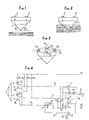
- the prism 1 is of cylindroconic shape with an apex angle of 90 °.
- the upper face of the prism 1 receives a transmitter 2 and a receiver 3, for example of the infrared cell type placed in the median axis of the cone defining the prism, the assembly forming a transmitter-receiver sensor.
- Fig. 1 shows a provision of light rays when the prism 1 is totally in the air.
- the emitted light ray shown in broken lines is reflected by two reflections at 90 °, the corresponding reflected ray, shown in solid line, is then perceived by the receiver 3.
- Fig. 2 shows the arrangement of the light rays when the prism 1 is partly immersed in the liquid 4. In such a case, the emitted light beam is refracted and passes into the liquid 4 so that the receiver 3 no longer receives light.
- the Metrology Service to which is subject, for example, the control of the combined block described in the European patent application 84 401652.7 above requires, at the level of the detection of the liquid, a so-called positive security operation.
- a positive security implies that the non-emission or non-reception of the above light beam can be detected regardless of the origin of the fault (presence of liquid at the detector, transmitter sensor defective receiver, fault in the electronic or electrical part to which the detector is connected ).
- the detector according to the invention comprises a dual sensor formed of a pair of sensors A and B.
- the double sensor is mounted in a prism similar to the prism 1 of FIGS. 1 and 2 and is connected to a suitable electronic circuit.
- Two emitter cells 2 and 2b and two receptor cells 3a and 3b, respectively, similar to the cells 2 and 3 in Fig. 1, are mounted in the same radius at the top of the cone at 180 ° by pair A and B of transceiver sensors at 90 ° to each other. Such an arrangement ensures that there is no interference between the sensors.
- the emitter cells 2 and 2b are respectively connected in parallel between a power supply + V and ground via resistors R1 and R3 and a shunt resistor R.
- the receptor cells 3a and 3 b have their inputs directly connected to the output of the emitter cells 2 a and 2 b and their outputs are connected between the + V supply and the ground O volt via a resistance bridge formed respectively by the resistors R2 , R6 and R4, R5.
- the logic levels of output of the two receptor cells 3a and 3b are preferably set so that a level O corresponds to an absence of liquid and a level 1 to the detection of a presence of liquid, in which case the receptor cells no longer receive light from the emitter cells.
- the outputs of the recipient cells 3a and 3b are then connected by links 4 and 5 to a NAND gate 6 NAND function.
- the two sensors must be at level 1 in order to obtain a level O at the output of the NAND circuit 6 in the case of liquid detection.
- comparators mounted between a reference source and the outputs of the various elements of the sensors.
- Comparators 7 and 8 have one of their inputs connected by links 4 and 5 to the corresponding outputs of the recipient cells 3a and 3b, while the other input of the comparators 7 and 8 is connected to a reference voltage U1.
- a comparator 9 is connected by a link directly to the output 10-11 of the emitter cells 2 and 2b and therefore the entry of the recipient cells 3a and 3b.
- the comparator 9 is further connected by its other input to a reference voltage U2.
- a fourth comparator, referenced 12 is also connected by a linkage 13-11 to the output of the emitter cells 2 and 2b and the other input receives a reference voltage U3.
- the output of the above NAND gate is further connected by a gate 14 to the first input of a second NAND gate 15 whose other input is connected by a link 16 to the common output of the comparators 7, 8 , 9 and 12.
- the output S of the NAND gate 16 corresponds to the output of the entire device.
- the supply links of the device are constituted by the connection + V and the connection O volt to ground.
- Both comparators 7 and 8 compare the voltages at the output of the recipient cells 3a and 3b with respect to the reference voltage U1.
- the voltage + V can not appear on the connection wires 4 or 5 except in the event of a short-circuit of the output or outputs of at least one sensors with the + V of the power supply.
- the voltage on the connecting wires 4 and 5 is then compared with the voltage U1.
- An appropriate setting of U1 (U1 less than or equal to + V) causes an alarm condition at the output of the comparator 7 or 8 corresponding when the voltage on the son 4 or 5 reaches the value U1.
- the assembly of the dual sensor and its associated electronic circuit constitute a positive security level detector.
Landscapes
- Physics & Mathematics (AREA)
- Electromagnetism (AREA)
- General Physics & Mathematics (AREA)
- Thermal Sciences (AREA)
- Fluid Mechanics (AREA)
- Geophysics And Detection Of Objects (AREA)
- Measurement Of Levels Of Liquids Or Fluent Solid Materials (AREA)
- Solid State Image Pick-Up Elements (AREA)
- Photometry And Measurement Of Optical Pulse Characteristics (AREA)
Priority Applications (4)
| Application Number | Priority Date | Filing Date | Title |
|---|---|---|---|
| DE8686400911T DE3663999D1 (en) | 1986-04-24 | 1986-04-24 | Optico-electronic level detector with double pick-up elements |
| AT86400911T ATE44094T1 (de) | 1986-04-24 | 1986-04-24 | Elektronischer optikfuellstandsdetektor mit doppeltem messwertaufnehmer. |
| DE198686400911T DE245563T1 (de) | 1986-04-24 | 1986-04-24 | Elektrooptischer fuellstandsdetektor mit doppeltem messwertaufnehmer. |
| EP86400911A EP0245563B1 (de) | 1986-04-24 | 1986-04-24 | Elektronischer Optikfüllstandsdetektor mit doppeltem Messwertaufnehmer |
Applications Claiming Priority (1)
| Application Number | Priority Date | Filing Date | Title |
|---|---|---|---|
| EP86400911A EP0245563B1 (de) | 1986-04-24 | 1986-04-24 | Elektronischer Optikfüllstandsdetektor mit doppeltem Messwertaufnehmer |
Publications (2)
| Publication Number | Publication Date |
|---|---|
| EP0245563A1 true EP0245563A1 (de) | 1987-11-19 |
| EP0245563B1 EP0245563B1 (de) | 1989-06-14 |
Family
ID=8196298
Family Applications (1)
| Application Number | Title | Priority Date | Filing Date |
|---|---|---|---|
| EP86400911A Expired EP0245563B1 (de) | 1986-04-24 | 1986-04-24 | Elektronischer Optikfüllstandsdetektor mit doppeltem Messwertaufnehmer |
Country Status (3)
| Country | Link |
|---|---|
| EP (1) | EP0245563B1 (de) |
| AT (1) | ATE44094T1 (de) |
| DE (2) | DE3663999D1 (de) |
Cited By (3)
| Publication number | Priority date | Publication date | Assignee | Title |
|---|---|---|---|---|
| EP0460432A3 (en) * | 1990-05-29 | 1992-04-15 | Ac & R Components, Inc. | Oil level control system |
| FR2704647A1 (fr) * | 1993-04-30 | 1994-11-04 | Luro Sarl Ets | Dispositif de mesure à haute précision et auto-contrôle de la hauteur d'un liquide dans une enceinte. |
| CN109239514A (zh) * | 2018-08-03 | 2019-01-18 | 重庆川仪自动化股份有限公司 | 一种液位计传感器短路、开路检测电路 |
Families Citing this family (2)
| Publication number | Priority date | Publication date | Assignee | Title |
|---|---|---|---|---|
| DE4102106C2 (de) * | 1991-01-25 | 1994-01-13 | Honeywell Regelsysteme Gmbh | Füllstandsensor |
| CN110361067B (zh) * | 2019-07-12 | 2021-01-01 | 彩虹(合肥)液晶玻璃有限公司 | 一种液面高度测量装置 |
Citations (6)
| Publication number | Priority date | Publication date | Assignee | Title |
|---|---|---|---|---|
| CH404224A (de) * | 1962-12-19 | 1965-12-15 | Foerderung Forschung Gmbh | Flüssigkeits-Überwachungs-Detektor |
| FR2238919A2 (en) * | 1973-07-26 | 1975-02-21 | Illinois Tool Works | Optical indicator for liquid level in tank - involves transparent blocks with V-shaped bottoms with lamp |
| GB1518492A (en) * | 1977-02-04 | 1978-07-19 | Ford Motor Co | Liquid level warning device |
| CH615995A5 (en) * | 1977-05-10 | 1980-02-29 | Benno Perren | Electrooptic device for detecting the presence of liquid. |
| DE2927449A1 (de) * | 1979-07-06 | 1981-01-15 | Siemens Ag | Optoelektronischer fluessigkeitsdetektor |
| DE3533523A1 (de) * | 1984-09-22 | 1986-04-17 | Sharp K.K., Osaka | Ausfall-detektor |
-
1986
- 1986-04-24 DE DE8686400911T patent/DE3663999D1/de not_active Expired
- 1986-04-24 EP EP86400911A patent/EP0245563B1/de not_active Expired
- 1986-04-24 DE DE198686400911T patent/DE245563T1/de active Pending
- 1986-04-24 AT AT86400911T patent/ATE44094T1/de not_active IP Right Cessation
Patent Citations (6)
| Publication number | Priority date | Publication date | Assignee | Title |
|---|---|---|---|---|
| CH404224A (de) * | 1962-12-19 | 1965-12-15 | Foerderung Forschung Gmbh | Flüssigkeits-Überwachungs-Detektor |
| FR2238919A2 (en) * | 1973-07-26 | 1975-02-21 | Illinois Tool Works | Optical indicator for liquid level in tank - involves transparent blocks with V-shaped bottoms with lamp |
| GB1518492A (en) * | 1977-02-04 | 1978-07-19 | Ford Motor Co | Liquid level warning device |
| CH615995A5 (en) * | 1977-05-10 | 1980-02-29 | Benno Perren | Electrooptic device for detecting the presence of liquid. |
| DE2927449A1 (de) * | 1979-07-06 | 1981-01-15 | Siemens Ag | Optoelektronischer fluessigkeitsdetektor |
| DE3533523A1 (de) * | 1984-09-22 | 1986-04-17 | Sharp K.K., Osaka | Ausfall-detektor |
Non-Patent Citations (2)
| Title |
|---|
| EDN MAGAZINE; vol. 26, 14 Octobre 1981, page 379, Boston, Mass., US; E.J. WHITESELL: "Schmitt triggers isolate coax faults" * |
| PRODUCT ENGINEERING, vol. 39, no. 20, 23 septembre 1968, pages 81,82: "Optical switch uses reflection to monitor the level of liquid" * |
Cited By (3)
| Publication number | Priority date | Publication date | Assignee | Title |
|---|---|---|---|---|
| EP0460432A3 (en) * | 1990-05-29 | 1992-04-15 | Ac & R Components, Inc. | Oil level control system |
| FR2704647A1 (fr) * | 1993-04-30 | 1994-11-04 | Luro Sarl Ets | Dispositif de mesure à haute précision et auto-contrôle de la hauteur d'un liquide dans une enceinte. |
| CN109239514A (zh) * | 2018-08-03 | 2019-01-18 | 重庆川仪自动化股份有限公司 | 一种液位计传感器短路、开路检测电路 |
Also Published As
| Publication number | Publication date |
|---|---|
| EP0245563B1 (de) | 1989-06-14 |
| DE3663999D1 (en) | 1989-07-20 |
| ATE44094T1 (de) | 1989-06-15 |
| DE245563T1 (de) | 1988-03-17 |
Similar Documents
| Publication | Publication Date | Title |
|---|---|---|
| US4803470A (en) | Substance detector device | |
| EP0021945B1 (de) | Durch elasto-optischen Effekt funktionierendes Hydrophon mit Monomode-Lichtleitfaser | |
| US3877821A (en) | Apparatus for detecting flaws using an array of photo sensitive devices | |
| US6455854B1 (en) | Infrared radiation detector for monitoring the presence of alkanes | |
| EP0245563B1 (de) | Elektronischer Optikfüllstandsdetektor mit doppeltem Messwertaufnehmer | |
| US3664752A (en) | Photoelectric measuring devices | |
| FR2722291A1 (fr) | Dispositif pour la detection d'un etat de surface d'une vitre de vehicule, et notamment pour la detection de las presence de gouttes d'eau sur un pare-brise | |
| EP0055319B1 (de) | Rauchmelder nach dem Lichtstreuungsprinzip mit Selbstüberwachung | |
| FR2478141A1 (fr) | Appareil a plusieurs capteurs pour la detection de fils detaches | |
| EP0374043A1 (de) | Verfahren zum Analysieren von optischen Komponenten, optischen Fasern oder Netzwerken von optischen Leitern durch Zeitbereichsreflektometrie und Zeitbereichsreflektometer | |
| FR2633055A2 (fr) | Perfectionnements aux testeurs de circuits | |
| EP2069813B1 (de) | Verfahren und einrichtung zur charakterisierung eines sich durch eine probe ausbreitenden elektrischen signals | |
| EP0497649A1 (de) | Verfahren und Vorrichtung zur Ermittlung der Oberflächenbeschaffenheit eines lichtdurchlässigen optischen Elements | |
| FR2666163A1 (fr) | Dispositif opto-electronique de detection de fumees ou de gaz en suspension dans l'air. | |
| JPH0827293B2 (ja) | 液体センサ | |
| EP0120116A2 (de) | Gerät zur automatischen Geschwindigkeitskontrolle von fahrenden Kraftfahrzeugen und mit Unterscheidungsmitteln, insbesondere zum Unterscheiden von Lastkraftwagen und Personenkraftwagen | |
| JPH08184556A (ja) | 光式ガス検知装置 | |
| WO2020234309A1 (fr) | Capteur acoustique à fibre optique et système de mesure, véhicule et procédé de mesure associés | |
| FR2784456A1 (fr) | Dispositif de mesure de distance a effet magneto-optique et chaine de mesure incorporant ce dispositif | |
| EP2132522A2 (de) | Optisches metrologiesystem | |
| FR2478815A1 (fr) | Procede et appareil d'evaluation de la visibilite | |
| FR2567651A1 (fr) | Equipement de mesure de vitesse d'un projectile par interferometrie utilisant un faisceau laser propage par un guide d'onde optique unique | |
| BE864281Q (fr) | Dispositif pour le controle de documents | |
| FR3118130A1 (fr) | Dispositif d’illumination et dispositif d’imagerie comportant un tel dispositif | |
| FR2505045A1 (fr) | Dispositif de localisation d'une cassure d'une fibre optique transmettant deux signaux lumineux de longueurs d'onde differentes |
Legal Events
| Date | Code | Title | Description |
|---|---|---|---|
| PUAI | Public reference made under article 153(3) epc to a published international application that has entered the european phase |
Free format text: ORIGINAL CODE: 0009012 |
|
| 17P | Request for examination filed |
Effective date: 19860502 |
|
| AK | Designated contracting states |
Kind code of ref document: A1 Designated state(s): AT BE CH DE FR GB IT LI LU NL SE |
|
| ITCL | It: translation for ep claims filed |
Representative=s name: STUDIO ING. ALFREDO RAIMONDI |
|
| TCNL | Nl: translation of patent claims filed | ||
| TCAT | At: translation of patent claims filed | ||
| DET | De: translation of patent claims | ||
| 17Q | First examination report despatched |
Effective date: 19880203 |
|
| GRAA | (expected) grant |
Free format text: ORIGINAL CODE: 0009210 |
|
| AK | Designated contracting states |
Kind code of ref document: B1 Designated state(s): AT BE CH DE FR GB IT LI LU NL SE |
|
| REF | Corresponds to: |
Ref document number: 44094 Country of ref document: AT Date of ref document: 19890615 Kind code of ref document: T |
|
| REF | Corresponds to: |
Ref document number: 3663999 Country of ref document: DE Date of ref document: 19890720 |
|
| ITF | It: translation for a ep patent filed | ||
| GBT | Gb: translation of ep patent filed (gb section 77(6)(a)/1977) | ||
| PLBE | No opposition filed within time limit |
Free format text: ORIGINAL CODE: 0009261 |
|
| STAA | Information on the status of an ep patent application or granted ep patent |
Free format text: STATUS: NO OPPOSITION FILED WITHIN TIME LIMIT |
|
| 26N | No opposition filed | ||
| ITTA | It: last paid annual fee | ||
| PGFP | Annual fee paid to national office [announced via postgrant information from national office to epo] |
Ref country code: FR Payment date: 19940307 Year of fee payment: 9 |
|
| PGFP | Annual fee paid to national office [announced via postgrant information from national office to epo] |
Ref country code: GB Payment date: 19940325 Year of fee payment: 9 |
|
| PGFP | Annual fee paid to national office [announced via postgrant information from national office to epo] |
Ref country code: CH Payment date: 19940328 Year of fee payment: 9 |
|
| PGFP | Annual fee paid to national office [announced via postgrant information from national office to epo] |
Ref country code: LU Payment date: 19940331 Year of fee payment: 9 Ref country code: BE Payment date: 19940331 Year of fee payment: 9 |
|
| PGFP | Annual fee paid to national office [announced via postgrant information from national office to epo] |
Ref country code: AT Payment date: 19940407 Year of fee payment: 9 |
|
| PGFP | Annual fee paid to national office [announced via postgrant information from national office to epo] |
Ref country code: SE Payment date: 19940418 Year of fee payment: 9 |
|
| PGFP | Annual fee paid to national office [announced via postgrant information from national office to epo] |
Ref country code: NL Payment date: 19940430 Year of fee payment: 9 |
|
| PGFP | Annual fee paid to national office [announced via postgrant information from national office to epo] |
Ref country code: DE Payment date: 19940505 Year of fee payment: 9 |
|
| EPTA | Lu: last paid annual fee | ||
| EAL | Se: european patent in force in sweden |
Ref document number: 86400911.3 |
|
| PG25 | Lapsed in a contracting state [announced via postgrant information from national office to epo] |
Ref country code: LU Free format text: LAPSE BECAUSE OF NON-PAYMENT OF DUE FEES Effective date: 19950424 Ref country code: GB Effective date: 19950424 Ref country code: AT Effective date: 19950424 |
|
| PG25 | Lapsed in a contracting state [announced via postgrant information from national office to epo] |
Ref country code: SE Effective date: 19950425 |
|
| PG25 | Lapsed in a contracting state [announced via postgrant information from national office to epo] |
Ref country code: LI Effective date: 19950430 Ref country code: CH Effective date: 19950430 Ref country code: BE Effective date: 19950430 |
|
| BERE | Be: lapsed |
Owner name: EQUIPEMENT INDUSTRIEL NORMAND Effective date: 19950430 |
|
| PG25 | Lapsed in a contracting state [announced via postgrant information from national office to epo] |
Ref country code: NL Effective date: 19951101 |
|
| REG | Reference to a national code |
Ref country code: CH Ref legal event code: PL |
|
| GBPC | Gb: european patent ceased through non-payment of renewal fee |
Effective date: 19950424 |
|
| PG25 | Lapsed in a contracting state [announced via postgrant information from national office to epo] |
Ref country code: FR Effective date: 19951229 |
|
| NLV4 | Nl: lapsed or anulled due to non-payment of the annual fee |
Effective date: 19951101 |
|
| PG25 | Lapsed in a contracting state [announced via postgrant information from national office to epo] |
Ref country code: DE Effective date: 19960103 |
|
| EUG | Se: european patent has lapsed |
Ref document number: 86400911.3 |
|
| REG | Reference to a national code |
Ref country code: FR Ref legal event code: ST |
|
| PG25 | Lapsed in a contracting state [announced via postgrant information from national office to epo] |
Ref country code: IT Free format text: LAPSE BECAUSE OF NON-PAYMENT OF DUE FEES;WARNING: LAPSES OF ITALIAN PATENTS WITH EFFECTIVE DATE BEFORE 2007 MAY HAVE OCCURRED AT ANY TIME BEFORE 2007. THE CORRECT EFFECTIVE DATE MAY BE DIFFERENT FROM THE ONE RECORDED. Effective date: 20050424 |