EP0245638A2 - Ponceuse à excentrique munie de moyens pour modifier le mouvement de ponçage - Google Patents
Ponceuse à excentrique munie de moyens pour modifier le mouvement de ponçage Download PDFInfo
- Publication number
- EP0245638A2 EP0245638A2 EP19870104742 EP87104742A EP0245638A2 EP 0245638 A2 EP0245638 A2 EP 0245638A2 EP 19870104742 EP19870104742 EP 19870104742 EP 87104742 A EP87104742 A EP 87104742A EP 0245638 A2 EP0245638 A2 EP 0245638A2
- Authority
- EP
- European Patent Office
- Prior art keywords
- grinding
- friction
- eccentric
- housing
- drive shaft
- Prior art date
- Legal status (The legal status is an assumption and is not a legal conclusion. Google has not performed a legal analysis and makes no representation as to the accuracy of the status listed.)
- Granted
Links
Images

Classifications
-
- B—PERFORMING OPERATIONS; TRANSPORTING
- B24—GRINDING; POLISHING
- B24B—MACHINES, DEVICES, OR PROCESSES FOR GRINDING OR POLISHING; DRESSING OR CONDITIONING OF ABRADING SURFACES; FEEDING OF GRINDING, POLISHING, OR LAPPING AGENTS
- B24B23/00—Portable grinding machines, e.g. hand-guided; Accessories therefor
- B24B23/02—Portable grinding machines, e.g. hand-guided; Accessories therefor with rotating grinding tools; Accessories therefor
- B24B23/03—Portable grinding machines, e.g. hand-guided; Accessories therefor with rotating grinding tools; Accessories therefor the tool being driven in a combined movement
Definitions
- the invention is based on an eccentric grinder according to the preamble of the main claim.
- Such an eccentric grinder is available on the market and published in print in "Technical reports for metalworking" on April 3, 1983 under the title “Rotex, the new dimension of grinding”.
- the jump between real rough grinding and fine grinding is too big.
- it is obvious to provide a further gear stage with changed diameters of the friction or gear wheels but this is only conceivable in the known manner with a considerable enlargement of the gear part of the eccentric grinder.
- switching from one type of drive to another entails a relatively large increase in actuators. These have to be robust for construction site operation and therefore have to be designed to be large enough, but still remain prone to failure. When using sprockets, their teeth can be damaged if they are handled carelessly when switching.
- the eccentric sander according to the invention with the characterizing features of the main claim has the advantage of optimal grinding performance with the simplest, space-saving construction. It is also ensured in the simplest way that the correct type of grinding wheel is always assigned the correct grinding wheel hardness and the correct sanding sheet grit.
- assigning a grinding plate to the type of grinding by means of the design of this grinding plate with or that friction or toothed ring or without such a friction or toothed ring, only the grinding plate needs to be replaced.
- the desired drive type, the required sanding pad hardness and the sanding sheet grit are set in a single change.
- the grit of the sanding sheet with which the sanding plate is coated gives the specialist information about the type of sanding selected with the use of this sanding plate (coarse, medium, fine).
- the grit of the sanding sheet with which the sanding plate is coated gives the specialist information about the type of sanding selected with the use of this sanding plate (coarse, medium, fine).
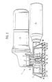
- FIG. 1 shows a view of an eccentric grinder equipped according to the invention, cut in the gearbox and grinding plate area
- FIG. 2 shows a view and a partial section as in FIG.
- An eccentric grinder 1 has a housing 2 for a grinding plate drive.
- a motor housing 3 The housing 2 is provided with a nozzle 4 for attaching a suction device 5.
- the housing 2 is flanged to the motor housing 3 and fastened there by means of screws 6.
- a drive shaft 7 protrudes from the motor housing 3.
- An intermediate piece 8 is screwed onto this.
- the intermediate piece 8 is designed as a crank and has a cylindrical recess 9 mounted eccentrically to the drive shaft 7.
- the eccentricity i.e. the distance between the longitudinal axis of the drive shaft 7 and the longitudinal axis of the recess 9 is denoted by e.
- two ball bearings 10 are inserted, which receive a support pin 11 for a grinding plate 12.
- the support pin 11 has a hexagon 13 and a threaded bore into which an Allen screw 14 can be screwed.
- the hexagon 13 and a locking washer 15 secure the trunnion 11 against axial displacement in the ball bearings 10.
- the grinding plate 12 is connected to the trunnion 11 by means of the Allen screw (screw with hexagon socket). It carries a glued-on, soft-elastic covering 16 which serves to receive an abrasive sheet 17.
- the housing 2 is provided with an inner ring gear 18 and an outer ring gear 19. These sprockets 18 and 19 are arranged concentrically with the drive shaft 7.
- the grinding plate 12 shown in FIG. 1 has an external toothed ring 20 which is aligned concentrically with the longitudinal axis of the trunnion 11 and thus eccentrically with the drive shaft 7.
- each abrasive grain on the grinding sheet 17 describes an elongated hypocycloid, which moves against the direction of rotation of the eccentric. This results in a greater removal than with grinding without a forced rolling movement.
- the grinding pattern lies approximately in the middle between rough grinding and fine grinding.
- the grinding takes place without forced rolling movement, i.e. with a grinding plate, not shown, without sprocket.
- This grinding plate is driven solely via the intermediate piece 8 with its eccentric recess 9.
- This grinding plate is freely rotatable on this support pin 11.
- This grinding plate consequently performs a movement that a cycloid carries out during grinding superimposed rotary motion follows.
- the superimposition of the rotary movement depends on the pressure when grinding.
- the path of each individual abrasive grain per eccentric revolution is very small, which results in a very fine grinding pattern.
- the removal is correspondingly low.
- This grinding movement is particularly well suited for grinding gradual transitions.
- a grinding plate 21 shown in FIG. 2 has an internal ring gear 22 which is intended to interact with the external ring gear 19 on the housing 2. Otherwise, the grinding plates 21 and 12 are the same.
- each of these grinding plates can expediently be equipped with a correspondingly grained grinding sheet 17.
- the hardness of the covering 16 should also vary depending on the grinding pattern, the correspondingly harder or softer covering can also be assigned to the respective grinding plate.
- the overall result of the solution according to the invention is that the best grinding movement, the best surface hardness and the best grain size can be selected on the grinding sheet for each intended grinding with the grinding plate. That is optimal.
Landscapes
- Engineering & Computer Science (AREA)
- Mechanical Engineering (AREA)
- Finish Polishing, Edge Sharpening, And Grinding By Specific Grinding Devices (AREA)
- Grinding Of Cylindrical And Plane Surfaces (AREA)
- Constituent Portions Of Griding Lathes, Driving, Sensing And Control (AREA)
Applications Claiming Priority (2)
| Application Number | Priority Date | Filing Date | Title |
|---|---|---|---|
| DE3615799 | 1986-05-10 | ||
| DE3615799A DE3615799C2 (de) | 1986-05-10 | 1986-05-10 | Exzenterschleifer mit einer Vorrichtung zum Verändern der Schleifbewegung |
Publications (3)
| Publication Number | Publication Date |
|---|---|
| EP0245638A2 true EP0245638A2 (fr) | 1987-11-19 |
| EP0245638A3 EP0245638A3 (en) | 1990-01-31 |
| EP0245638B1 EP0245638B1 (fr) | 1992-09-23 |
Family
ID=6300566
Family Applications (1)
| Application Number | Title | Priority Date | Filing Date |
|---|---|---|---|
| EP87104742A Expired - Lifetime EP0245638B1 (fr) | 1986-05-10 | 1987-03-31 | Ponceuse à excentrique munie de moyens pour modifier le mouvement de ponçage |
Country Status (4)
| Country | Link |
|---|---|
| US (1) | US4754575A (fr) |
| EP (1) | EP0245638B1 (fr) |
| JP (1) | JPH0710491B2 (fr) |
| DE (2) | DE3615799C2 (fr) |
Cited By (1)
| Publication number | Priority date | Publication date | Assignee | Title |
|---|---|---|---|---|
| EP0413956A3 (en) * | 1989-08-23 | 1991-04-24 | Robert Bosch Gmbh | Hand tool with grinding disc |
Families Citing this family (35)
| Publication number | Priority date | Publication date | Assignee | Title |
|---|---|---|---|---|
| DE3620136C5 (de) * | 1986-06-14 | 2007-01-11 | Robert Bosch Gmbh | Motorisch angetriebene Handschleifmaschine mit einem Exzenterantrieb |
| DE3805962A1 (de) * | 1988-02-25 | 1989-09-07 | Festo Kg | Tellerschleifmaschine |
| JPH0750141Y2 (ja) * | 1988-05-12 | 1995-11-15 | 宏明 安田 | 研磨用具 |
| JP3181580B2 (ja) * | 1989-03-02 | 2001-07-03 | ローベルト ボッシュ ゲゼルシャフト ミット ベシュレンクテル ハフツング | 偏心研削装置 |
| DE3906549A1 (de) * | 1989-03-02 | 1990-09-06 | Bosch Gmbh Robert | Exzenterschleifer |
| JP2523147Y2 (ja) * | 1990-04-27 | 1997-01-22 | 株式会社マキタ | 研磨機 |
| DE3926942A1 (de) * | 1989-08-14 | 1991-02-21 | Werner Blume | Vorrichtung zum aufrauhen und/oder entfernen von insbesondere wand- und fussbodenbelaegen |
| DE3942301C1 (fr) * | 1989-12-21 | 1991-02-14 | Robert Bosch Gmbh, 7000 Stuttgart, De | |
| DE9003410U1 (de) * | 1990-03-23 | 1990-06-28 | Nied, Hans Rainer, 8760 Miltenberg | Handschleifmaschine |
| US7004818B1 (en) | 1990-08-17 | 2006-02-28 | Haney Donald E | Sander with orbiting platen and abrasive |
| US5081794A (en) | 1990-08-17 | 1992-01-21 | Haney Donald E | Sander with orbiting platen and abrasive |
| USD332560S (en) | 1990-12-26 | 1993-01-19 | Nitto Kohki Co., Ltd. | Portable disk grinder |
| GB9123502D0 (en) * | 1991-11-06 | 1992-01-02 | Black & Decker Inc | Sanding apparatus |
| US5518442A (en) * | 1993-01-22 | 1996-05-21 | Porter-Cable Corporation | Sander |
| US5392568A (en) * | 1993-12-22 | 1995-02-28 | Black & Decker Inc. | Random orbit sander having braking member |
| US5580302A (en) * | 1994-02-28 | 1996-12-03 | Black & Decker Inc. | Random orbit sander having air directing baffle |
| GB9415011D0 (en) * | 1994-07-26 | 1994-09-14 | Black & Decker Inc | Improved oscillating hand tool |
| US5649367A (en) * | 1996-05-16 | 1997-07-22 | Blount, Inc. | Chain saw guide bar with identifying indicia |
| US5941765A (en) * | 1996-11-19 | 1999-08-24 | Porter Cable Corporation | Sander |
| USD416459S (en) | 1997-11-15 | 1999-11-16 | Black & Decker Inc. | Sander |
| US6213851B1 (en) | 1998-07-07 | 2001-04-10 | Delta International Machinery Corp. | Abrading apparatus |
| DE19963831B4 (de) * | 1999-12-30 | 2006-04-06 | Robert Bosch Gmbh | Exzentertellerschleifer mit einem Gehäuse |
| GB2380151B (en) * | 2001-07-20 | 2004-09-22 | Black & Decker Inc | Oscillating hand tool |
| US7198557B2 (en) * | 2001-08-02 | 2007-04-03 | Haney Donald E | Sanding machine incorporating multiple sanding motions |
| CN100427269C (zh) * | 2005-04-01 | 2008-10-22 | 王复春 | 一种双向旋转多功能抛光机 |
| US7029385B1 (en) * | 2005-07-27 | 2006-04-18 | Fu-Chun Wang | Two-way rotary multi-function polisher |
| DE102007007787A1 (de) * | 2007-02-16 | 2008-08-21 | Robert Bosch Gmbh | Schleifteller für eine Exzenterschleifmaschine |
| US8100745B2 (en) * | 2007-03-16 | 2012-01-24 | Black & Decker Inc. | Low vibration sander with a flexible top handle |
| US8172642B2 (en) | 2008-08-20 | 2012-05-08 | Black & Decker Inc. | Multi-sander |
| US9421682B2 (en) | 2011-07-18 | 2016-08-23 | Black & Decker Inc. | Multi-head power tool with reverse lock-out capability |
| US9956677B2 (en) | 2013-05-08 | 2018-05-01 | Black & Decker Inc. | Power tool with interchangeable power heads |
| DE102014109904A1 (de) | 2014-07-15 | 2016-01-21 | C. & E. Fein Gmbh | Exzenterschleifer |
| US10414014B2 (en) | 2017-09-19 | 2019-09-17 | Campbell Hausfeld, Llc | Multifunction rotary tool including driveshaft |
| US10603760B2 (en) | 2017-09-19 | 2020-03-31 | Campbell Hausfeld, Llc | Multifunction rotary tool including hub |
| CN115703199A (zh) * | 2021-08-09 | 2023-02-17 | 鼎朋企业股份有限公司 | 轨道运动研磨机的研磨盘稳定结构 |
Family Cites Families (3)
| Publication number | Priority date | Publication date | Assignee | Title |
|---|---|---|---|---|
| US3857206A (en) * | 1973-03-08 | 1974-12-31 | Nat Detroit Inc Co | Compound motion rubbing machine |
| DE2938704C2 (de) * | 1979-09-25 | 1984-03-15 | Festo-Maschinenfabrik Gottlieb Stoll, 7300 Esslingen | Exzentertellerschleifer |
| US4705038A (en) * | 1985-01-23 | 1987-11-10 | Dyonics, Inc. | Surgical system for powered instruments |
-
1986
- 1986-05-10 DE DE3615799A patent/DE3615799C2/de not_active Expired - Fee Related
-
1987
- 1987-03-24 US US07/030,068 patent/US4754575A/en not_active Expired - Fee Related
- 1987-03-31 EP EP87104742A patent/EP0245638B1/fr not_active Expired - Lifetime
- 1987-03-31 DE DE8787104742T patent/DE3781829D1/de not_active Expired - Lifetime
- 1987-05-11 JP JP62112663A patent/JPH0710491B2/ja not_active Expired - Lifetime
Cited By (1)
| Publication number | Priority date | Publication date | Assignee | Title |
|---|---|---|---|---|
| EP0413956A3 (en) * | 1989-08-23 | 1991-04-24 | Robert Bosch Gmbh | Hand tool with grinding disc |
Also Published As
| Publication number | Publication date |
|---|---|
| DE3781829D1 (de) | 1992-10-29 |
| US4754575A (en) | 1988-07-05 |
| JPS62277260A (ja) | 1987-12-02 |
| JPH0710491B2 (ja) | 1995-02-08 |
| DE3615799A1 (de) | 1987-11-12 |
| EP0245638A3 (en) | 1990-01-31 |
| DE3615799C2 (de) | 1994-10-13 |
| EP0245638B1 (fr) | 1992-09-23 |
Similar Documents
| Publication | Publication Date | Title |
|---|---|---|
| EP0245638B1 (fr) | Ponceuse à excentrique munie de moyens pour modifier le mouvement de ponçage | |
| EP0237854B1 (fr) | Ponceuse à excentrique munie d'un dispositif de variation du mouvement de ponçage | |
| DE3906549C2 (fr) | ||
| DE2742062C3 (de) | Schleifkopf | |
| EP0230621B1 (fr) | Ponceuse orbitale avec dispositif de modification du mouvement de ponçage | |
| EP0641621B1 (fr) | Dispositif d'entraînement rotatif | |
| DE19952108A1 (de) | Motorgetriebene Handschleifmaschine | |
| DE19953766C1 (de) | Hydraulische Axialkolbenmaschine | |
| DE3018775C2 (de) | Einrichtung zum Arretieren der Schleifspindel von Winkelschleifern | |
| DE3640516C1 (en) | Surgical bone saw | |
| DE19914956C2 (de) | Elektromotorisch antreibbares Schleifgerät | |
| DE2306876C2 (de) | Handschwingschleifer | |
| DE3402010C2 (de) | Vorrichtung zum Entrosten von Eisenteilen | |
| DE8303975U1 (de) | Vorrichtung zum schleifen und laeppen von ringfoermigen dichtflaechen | |
| EP1581365A1 (fr) | Ensemble palier servant a monter de maniere oscillante un disque de meulage sur un appareil de meulage | |
| DE60005496T2 (de) | Differentialsperre | |
| CH687963A5 (de) | Exzentertellerschleifer mit Schleiftellerbremse. | |
| DE29811654U1 (de) | Schwingschleifer | |
| DE29801109U1 (de) | Schwingschleifer | |
| DE102004002382B3 (de) | Rotierbares Werkzeug | |
| DE3929011A1 (de) | Spanneinrichtung an werkzeugmaschinen | |
| DE4434784C1 (de) | Maschine zum Schleifen des Randes hohler Gefäße | |
| DE830620C (de) | Vorrichtung zum Drehen des Werkstuecks auf Werkzeugmaschinen zum Bearbeiten, insbesondere Schleifen von Schraubenzuegen | |
| EP4703043A1 (fr) | Tête de lavage de réservoir | |
| DE267107C (fr) |
Legal Events
| Date | Code | Title | Description |
|---|---|---|---|
| PUAI | Public reference made under article 153(3) epc to a published international application that has entered the european phase |
Free format text: ORIGINAL CODE: 0009012 |
|
| AK | Designated contracting states |
Kind code of ref document: A2 Designated state(s): DE FR GB IT |
|
| PUAL | Search report despatched |
Free format text: ORIGINAL CODE: 0009013 |
|
| AK | Designated contracting states |
Kind code of ref document: A3 Designated state(s): DE FR GB IT |
|
| 17P | Request for examination filed |
Effective date: 19900718 |
|
| 17Q | First examination report despatched |
Effective date: 19911119 |
|
| RAP3 | Party data changed (applicant data changed or rights of an application transferred) |
Owner name: ROBERT BOSCH GMBH |
|
| GRAA | (expected) grant |
Free format text: ORIGINAL CODE: 0009210 |
|
| AK | Designated contracting states |
Kind code of ref document: B1 Designated state(s): DE FR GB IT |
|
| ET | Fr: translation filed | ||
| GBT | Gb: translation of ep patent filed (gb section 77(6)(a)/1977) | ||
| REF | Corresponds to: |
Ref document number: 3781829 Country of ref document: DE Date of ref document: 19921029 |
|
| ITF | It: translation for a ep patent filed | ||
| PLBE | No opposition filed within time limit |
Free format text: ORIGINAL CODE: 0009261 |
|
| STAA | Information on the status of an ep patent application or granted ep patent |
Free format text: STATUS: NO OPPOSITION FILED WITHIN TIME LIMIT |
|
| 26N | No opposition filed | ||
| PGFP | Annual fee paid to national office [announced via postgrant information from national office to epo] |
Ref country code: GB Payment date: 19940321 Year of fee payment: 8 |
|
| PGFP | Annual fee paid to national office [announced via postgrant information from national office to epo] |
Ref country code: FR Payment date: 19940330 Year of fee payment: 8 |
|
| PGFP | Annual fee paid to national office [announced via postgrant information from national office to epo] |
Ref country code: DE Payment date: 19940520 Year of fee payment: 8 |
|
| PG25 | Lapsed in a contracting state [announced via postgrant information from national office to epo] |
Ref country code: GB Effective date: 19950331 |
|
| GBPC | Gb: european patent ceased through non-payment of renewal fee |
Effective date: 19950331 |
|
| PG25 | Lapsed in a contracting state [announced via postgrant information from national office to epo] |
Ref country code: FR Free format text: LAPSE BECAUSE OF NON-PAYMENT OF DUE FEES Effective date: 19951130 |
|
| PG25 | Lapsed in a contracting state [announced via postgrant information from national office to epo] |
Ref country code: DE Effective date: 19951201 |
|
| REG | Reference to a national code |
Ref country code: FR Ref legal event code: ST |
|
| PG25 | Lapsed in a contracting state [announced via postgrant information from national office to epo] |
Ref country code: IT Free format text: LAPSE BECAUSE OF NON-PAYMENT OF DUE FEES;WARNING: LAPSES OF ITALIAN PATENTS WITH EFFECTIVE DATE BEFORE 2007 MAY HAVE OCCURRED AT ANY TIME BEFORE 2007. THE CORRECT EFFECTIVE DATE MAY BE DIFFERENT FROM THE ONE RECORDED. Effective date: 20050331 |