EP0245827A2 - Appareil pour modifier la température de dispositifs, notamment d'outils - Google Patents
Appareil pour modifier la température de dispositifs, notamment d'outils Download PDFInfo
- Publication number
- EP0245827A2 EP0245827A2 EP87106826A EP87106826A EP0245827A2 EP 0245827 A2 EP0245827 A2 EP 0245827A2 EP 87106826 A EP87106826 A EP 87106826A EP 87106826 A EP87106826 A EP 87106826A EP 0245827 A2 EP0245827 A2 EP 0245827A2
- Authority
- EP
- European Patent Office
- Prior art keywords
- temperature
- liquid
- reference signal
- output
- heating
- Prior art date
- Legal status (The legal status is an assumption and is not a legal conclusion. Google has not performed a legal analysis and makes no representation as to the accuracy of the status listed.)
- Ceased
Links
Images

Classifications
-
- F—MECHANICAL ENGINEERING; LIGHTING; HEATING; WEAPONS; BLASTING
- F28—HEAT EXCHANGE IN GENERAL
- F28D—HEAT-EXCHANGE APPARATUS, NOT PROVIDED FOR IN ANOTHER SUBCLASS, IN WHICH THE HEAT-EXCHANGE MEDIA DO NOT COME INTO DIRECT CONTACT
- F28D15/00—Heat-exchange apparatus with the intermediate heat-transfer medium in closed tubes passing into or through the conduit walls ; Heat-exchange apparatus employing intermediate heat-transfer medium or bodies
-
- B—PERFORMING OPERATIONS; TRANSPORTING
- B29—WORKING OF PLASTICS; WORKING OF SUBSTANCES IN A PLASTIC STATE IN GENERAL
- B29C—SHAPING OR JOINING OF PLASTICS; SHAPING OF MATERIAL IN A PLASTIC STATE, NOT OTHERWISE PROVIDED FOR; AFTER-TREATMENT OF THE SHAPED PRODUCTS, e.g. REPAIRING
- B29C35/00—Heating, cooling or curing, e.g. crosslinking or vulcanising; Apparatus therefor
- B29C35/007—Tempering units for temperature control of moulds or cores, e.g. comprising heat exchangers, controlled valves, temperature-controlled circuits for fluids
-
- B—PERFORMING OPERATIONS; TRANSPORTING
- B29—WORKING OF PLASTICS; WORKING OF SUBSTANCES IN A PLASTIC STATE IN GENERAL
- B29C—SHAPING OR JOINING OF PLASTICS; SHAPING OF MATERIAL IN A PLASTIC STATE, NOT OTHERWISE PROVIDED FOR; AFTER-TREATMENT OF THE SHAPED PRODUCTS, e.g. REPAIRING
- B29C45/00—Injection moulding, i.e. forcing the required volume of moulding material through a nozzle into a closed mould; Apparatus therefor
- B29C45/17—Component parts, details or accessories; Auxiliary operations
- B29C45/72—Heating or cooling
- B29C45/73—Heating or cooling of the mould
- B29C45/7306—Control circuits therefor
-
- F—MECHANICAL ENGINEERING; LIGHTING; HEATING; WEAPONS; BLASTING
- F28—HEAT EXCHANGE IN GENERAL
- F28D—HEAT-EXCHANGE APPARATUS, NOT PROVIDED FOR IN ANOTHER SUBCLASS, IN WHICH THE HEAT-EXCHANGE MEDIA DO NOT COME INTO DIRECT CONTACT
- F28D1/00—Heat-exchange apparatus having stationary conduit assemblies for one heat-exchange medium only, the media being in contact with different sides of the conduit wall, in which the other heat-exchange medium is a large body of fluid, e.g. domestic or motor car radiators
- F28D1/02—Heat-exchange apparatus having stationary conduit assemblies for one heat-exchange medium only, the media being in contact with different sides of the conduit wall, in which the other heat-exchange medium is a large body of fluid, e.g. domestic or motor car radiators with heat-exchange conduits immersed in the body of fluid
- F28D1/0233—Heat-exchange apparatus having stationary conduit assemblies for one heat-exchange medium only, the media being in contact with different sides of the conduit wall, in which the other heat-exchange medium is a large body of fluid, e.g. domestic or motor car radiators with heat-exchange conduits immersed in the body of fluid with air flow channels
- F28D1/024—Heat-exchange apparatus having stationary conduit assemblies for one heat-exchange medium only, the media being in contact with different sides of the conduit wall, in which the other heat-exchange medium is a large body of fluid, e.g. domestic or motor car radiators with heat-exchange conduits immersed in the body of fluid with air flow channels with an air driving element
-
- F—MECHANICAL ENGINEERING; LIGHTING; HEATING; WEAPONS; BLASTING
- F28—HEAT EXCHANGE IN GENERAL
- F28F—DETAILS OF HEAT-EXCHANGE AND HEAT-TRANSFER APPARATUS, OF GENERAL APPLICATION
- F28F27/00—Control arrangements or safety devices specially adapted for heat-exchange or heat-transfer apparatus
-
- G—PHYSICS
- G05—CONTROLLING; REGULATING
- G05D—SYSTEMS FOR CONTROLLING OR REGULATING NON-ELECTRIC VARIABLES
- G05D23/00—Control of temperature
- G05D23/19—Control of temperature characterised by the use of electric means
- G05D23/1919—Control of temperature characterised by the use of electric means characterised by the type of controller
-
- G—PHYSICS
- G05—CONTROLLING; REGULATING
- G05D—SYSTEMS FOR CONTROLLING OR REGULATING NON-ELECTRIC VARIABLES
- G05D23/00—Control of temperature
- G05D23/19—Control of temperature characterised by the use of electric means
- G05D23/20—Control of temperature characterised by the use of electric means with sensing elements having variation of electric or magnetic properties with change of temperature
- G05D23/24—Control of temperature characterised by the use of electric means with sensing elements having variation of electric or magnetic properties with change of temperature the sensing element having a resistance varying with temperature, e.g. a thermistor
-
- F—MECHANICAL ENGINEERING; LIGHTING; HEATING; WEAPONS; BLASTING
- F28—HEAT EXCHANGE IN GENERAL
- F28D—HEAT-EXCHANGE APPARATUS, NOT PROVIDED FOR IN ANOTHER SUBCLASS, IN WHICH THE HEAT-EXCHANGE MEDIA DO NOT COME INTO DIRECT CONTACT
- F28D21/00—Heat-exchange apparatus not covered by any of the groups F28D1/00 - F28D20/00
- F28D2021/0019—Other heat exchangers for particular applications; Heat exchange systems not otherwise provided for
- F28D2021/0077—Other heat exchangers for particular applications; Heat exchange systems not otherwise provided for for tempering, e.g. with cooling or heating circuits for temperature control of elements
Definitions
- the invention relates to a device for adjusting the temperature of devices, in particular tools, by circulating a heat-transferring liquid, this device comprising a container storing the liquid, a heating element in contact with the liquid, a pump which allows the liquid to circulate through the channel of the device, a temperature sensor measuring the temperature of the liquid, a temperature control unit which engages in the power supply of the radiator and is connected to the temperature sensor, and to a reference signal transmitter determining the desired temperature, and furthermore has a construction unit which ensures the cooling of the device, the reference signal transmitter being connected to an input of a difference former is.
- the designers of the devices have made sure that the medium used for temperature control, in most cases oil (in some cases water), reaches the corresponding parts of the device and can exert its effect there by forming appropriate channels.
- the regulation of the temperature is ensured with the aid of devices which allow a predetermined amount of liquid to flow through the channels of the device at a certain constant flow rate.
- the path of the liquid leads via the radiator, by means of which the liquid is heated, a pipe coil through which a cooling liquid flows is also inserted into the liquid path, with the aid of which the liquid can be cooled.
- the temperature of the liquid emerging from the control device is generally used for the temperature control, and the temperature prevailing inside the tool is inferred from this.
- the most precise regulation could be ensured by temperature sensors attached to the body of the tool or device, for the arrangement of such
- one temperature control device is even connected to several tools per shift, whereby the calibration of this device for the various temperature sensors arranged in it can only be solved in a complicated manner.
- the number of temperature control devices to be connected to the device must correspond to the number of different temperature zones to be trained.
- Each temperature control device is suitable for maintaining only a single predetermined temperature and is provided with an outlet and a return flow connection.
- the individual desired temperatures can be set individually with the temperature control devices. The possibility described here carries certain dangers. If the different temperatures are not set precisely or are possibly missed, unnecessarily large temperature differences can arise between the various parts of the same device to be controlled, which lead to the formation of internal stresses and to a deterioration in the quality of the tool. Experience has shown that it is not practical to maintain a temperature difference of more than ⁇ 20 ° C between the different parts of an average tool.
- the above-mentioned properties can be found in most temperature regulators from the Swiss company REGLOPLAS AG, for example in the types 15S, 150 KL, 150.
- the cooling realized by means of the cooling liquid circulated in a closed coil can be regarded as disadvantageous, since during the heating following cooling, the liquid in the coil must also be heated, which means a superfluous expenditure of energy and increases the time required for the regulation.
- the basic problem to be solved with the invention is the perfection of the devices regulating the temperature of devices, primarily the reduction of the tolerance range while maintaining the desired temperature.
- the object to be achieved with the invention is also to create a device which is easier to use in practice, and to reduce the control time constant and to minimize the energy losses.
- the invention is based on the knowledge that the actual temperature of the devices can be approximated with the average of the temperatures of the emerging and the returning liquid and this average can serve as the basis for the temperature control.
- the effectiveness of the regulation solved in this way can be further increased in that the cooling is not achieved with a tube coil through which the cooling liquid flows and which is arranged in the path of the medium, but with such a heat exchanger in which the cooling is carried out by air conveyed by a fan is secured.
- a device for adjusting the temperature of devices, in particular tools Circulation of a heat-transferring liquid comprising a liquid-storing container, a heating element in contact with the liquid, a pump which allows the liquid to circulate through a channel of the device designed for this purpose, a temperature sensor measuring the temperature of the liquid and a power supply of the radiator intervening temperature control unit connected to the temperature sensor and to a reference signal transmitter determining the desired temperature, furthermore having a construction unit securing the cooling of the device, the reference signal transmitter being connected to an input of a difference former and, according to the invention, in one which circulates the liquid closed flow circuit a heat exchanger, which is connected to a fan, is inserted, that two further separate the temperature of the exiting and returning Liquid-detecting temperature sensors and in the temperature control unit a mean value generator simulating the temperature of the device based on the signals of the two temperature sensors are provided, the output of the mean value generator being connected to the other input of the difference former and the output of the difference former
- the heat exchanger enables a horizontally directed air flow, the vertically directed circulation is hindered by the use of horizontal fins.
- one side of the heat exchanger is connected to a funnel which widens upwards and is open at the top, and the other side is connected to a fan which generates a horizontal air flow.
- the above-mentioned average (average value) is used as the basis for the control.
- this mean value can be influenced to a lesser extent with knowledge of some empirical values and the actual ambient temperature.
- a plurality of heating / cooling units are arranged in a common construction housing, each of which is assigned a control unit.
- a single device is sufficient to regulate the temperature of the tool, for example by connecting the fixed part and the movable part at the same time.
- the temperature control device designed according to the invention enables faster reaching and more precise maintenance of the operating temperature, its energy requirement is lower, no cooling water connection is required, the use of the device according to the invention excludes subjective setting errors, the device adapts flexibly to the operating conditions, since the conventional devices, there is no need to connect multiple devices to a single tool.
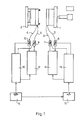
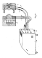
- FIG. 1 An injection molding tool is shown schematically in FIG. 1, the temperature of which can be regulated to a predetermined value using the device designed according to the invention.
- the tool consists of two parts, a fixed side 1 and a moving side 2, in the interior of which channels for the liquid used for heating or cooling are formed, which are connected via connecting pieces to inlet lines 3 and 4 and to outlet lines 5 and 6 .
- the fluid path closes after the insertion of temperature sensors 7, 8 or 9, 10, each via a heating circuit cooling unit 11 or 12 of the same design, which has the necessary heating and cooling of the liquid and has a closed flow circuit.
- the desired temperature of the fixed side 1 of the tool can be determined using of a reference signal transmitter 13 can be set, while the temperature of the moving side 2 of the tool can be set by means of a reference signal transmitter 14.
- a control unit 15 or 16 is connected to the heating-cooling unit 11 or 12, which is connected to the reference signal transmitters 13 or 14 and the temperature sensors 7, 8 or 9, 10.
- there can be at most a difference of 20-25 ° C between the temperatures of the fixed side 1 and the moving side 2 therefore only one of the two reference signal transmitters 13 and 14 can be set independently of the other.
- the reference signal generator 13 receives the output signal of the reference signal generator 14 and the reference signal generator 13 only allows the temperature of the control unit 15 which sets the temperature of the fixed side 1 to be within the limits of, for example, ⁇ 20 ° C. in relation to that to be set using the control unit 16 Setting the temperature.
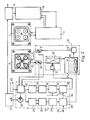
- the arrangement shown in FIG. 1 was repeated schematically in FIG. 2, but the internal structure of the heating-cooling unit 12 assigned to the moving side 2 and the control unit 16 are also illustrated in more detail.
- the fixed side 1 and the moving side 2 of the tool are shown here on the front of the work surface. It can be clearly seen from the figure that the four nests of the tool are completely surrounded by a channel which receives the heating / cooling medium.
- the heating-cooling unit 12 In the heating-cooling unit 12 are an oil tank 17, on the bottom of which a radiator 18, a circulation pump 19 inserted into the outlet line of the oil container 17, a heat exchanger 20 switched on in the line returning from the tool and a fan 21 which triggers the heat exchange are arranged. Oil circulates in the closed flow circuit with the aid of the circulation pump 19 in accordance with a constant flow volume. Pressure sensors (not shown in the figure) are arranged on the inlet and outlet connections of the circuit, which, with the aid of appropriate safety circuits, ensure that the oil is only circulated under approved pressure conditions. In a similar manner, a level detector arranged in the oil container 17 indicates when the oil level assumes a value outside of permitted limits.
- control unit 16 receives the temperature reference signal set by the reference signal generator 14, while an averager 22 arranged in the control unit 16 receives the outflow and inflow temperature signals of the moving side 2 from the temperature sensors 9, 10 and the signal about those prevailing in the vicinity of the tool Receives temperature from a temperature sensor 23.
- the output of the reference signal generator 14 and the output of the mean value generator 22 are each connected to an input of a difference generator 24, the output of which branches in two directions.
- the branches are sensitive to the sign of the differential signal appearing at the output, and only one of these two branches functions at a time.
- the branch belonging to the negative sign (ie if the required temperature is below the actual one) has an integrator 25, a comparator 26 connected to it in chain, a monostable multivibrator 27 and one by switching it off gear-controlled switch 28, the latter switching the mains voltage to the radiator 18 via a mains connection 29.
- the branch belonging to the positive sign has a similar structure and has an integrator 30, a comparator 31, a monostable multivibrator 32 and a controlled switch 33, the controlled switch 33 controlling the function of the fan 21 with its output.
- the monostable multivibrator 32 is synchronized with the network, each start of the pulse begins at the zero crossing of the network signal and ensures a signal with a complete wave for the fan 21 at all times.
- the synchronous run is symbolically illustrated in FIG. 2 by line 34. Both branches give pulses of a certain length to the actuated means with a frequency proportional to the size of the difference signal, i.e. to the radiator 18 or the fan 21.
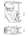
- FIGS. 3 and 4 illustrate the construction of the device according to the invention.
- the device is provided with a rollable, or in a given position attachable construction housing 35, in which two uniform heating-cooling units 11, 12 are arranged side by side in such a way that their oil tank 17 and 36 is below and above the oil tank 17, the associated heat exchanger 20 are arranged with the fan 21 and next to it the other heat exchanger and fan belonging to the oil container 36 and not shown separately in the figure.
- the motor 37 drives the circulation pump 19.
- the construction housing 35 is designed with an inclined end wall and the electronic units are arranged in a block formed underneath.
- the construction housing 35 also has a rear wall 40, on which the connections of the inlet lines 3, 4 and the outlet line lines 5, 6 are formed.
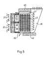
- the heat exchanger 20 is designed for a horizontal air flow, i.e. between an upper manifold 41 and a lower manifold 42, a plurality of vertical connecting pipes 43 are attached, to which a large number of horizontal lamellae are fastened vertically.
- the ventilation is ensured by two fans 21a and 21b arranged one above the other, which let the air flow between the horizontal fins 44.
- the outflowing air arrives in a funnel 45 which widens upwards and is open at the top and allows the air to escape upwards into the open.
- the heat exchanger 20 is completely surrounded by a heat insulation sleeve 46.
- the schematically illustrated construction is advantageous on the one hand, because when the fans are in a standing state, no natural cooling can develop, the heat loss is minimal.
- the permanent connection of the heat exchanger 20 thus does not cause any significant heat loss in heating operation, but intensive cooling begins when the fans are switched on.
- Another advantage is that the horizontal front air intake and the vertical exhaust allow two or more units to be arranged side by side.
- FIG. 6 shows the device according to the invention in a perspective view and the injection molding tool connected to it, the latter being drawn on an enlarged scale for better illustration.
- the device according to the invention functions as follows wise:
- the temperatures of the fixed side 1 and the moving side 2 of the injection mold are determined by the technology of the injection molding.
- the basic task of the device according to the invention is to ensure that the tool reaches this temperature as quickly and precisely as possible when it is started up, and maintains it within narrow tolerance limits during injection molding despite the changing thermal load.
- the double design enables the connection of both tool sides and that the closed circulation circuit of the oil also includes both the possibility of heating and the possibility of cooling.
- the averager 22 determines the simulated temperature T sz of the tool using this equation, and derives the value of k from the signal from the temperature sensor 23.
- the output signal of the difference former 24 assumes a positive or negative sign, while the size of these output signals depends on the size of the difference. If this output signal has a negative sign, ie the tool has not yet reached the desired temperature, heating is required and the branch controlling the radiator 18 starts to operate.
- a sawtooth pulse that increases in proportion to the difference appears.
- the monostable multivibrator 27 When it reaches a reference value that determines the threshold value of the comparator 26, the monostable multivibrator 27 switches on the heating of the radiator 18 for a predetermined period of time. In the case of a large difference signal, the monostable multivibrator 27 receives a new control pulse before the tipping back, whereby constant heating is achieved. In addition to the correct selection of the time constant and the threshold values, the control can be made extremely effective with the lower values of the difference values.
- the output signal of the difference former 24 changes its sign, the heating branch switches off and the fan 21 comes into operation by completely similar regulation.
- the intensive heat exchange quickly reduces the temperature of the circulating oil and removes the excess heat from the tool.
- the reference signal generator 13 of the other circuit already receives its reference signal from the reference signal generator 14 of the first circuit, relative to which it can only make changes within predetermined limits. For example, if a temperature of 80 ° C was set on the reference signal transmitter 14, the ⁇ 20 ° C scale of the reference signal transmitter 13 only allows the temperature of the other circuit to be set within the limits of 60 and 80 ° C. This prevents dangerously high temperature differences from forming in the tool, which at the same time enables the selection of technologies which require temperature differences of a predetermined size.
- the control reference signal of the reference signal generator 14 can be branched off to the reference signal generator 13 to other reference signal generators, which indicates the possibility of connecting further circuits.
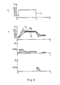
- the independent variable of Fig. 7 is the time axis.
- the reference signal T j is set to 80 ° C.
- the radiator 18 then switches on and the temperatures T a and T b change according to the figure.
- the peculiarity of the control is that the temperature T a greatly exceeds the value T j , so the tool heats up in a relatively short time.
- This Circumstances are indicated by an indicator connected to the difference generator 24.
- the course of the heating power P f is also illustrated in the figure.
- the heating works with 100% output in the initial period, then it drops and takes on an ever decreasing value.
- the curve P sz shows the heat absorption or heat emission of the tool, which due to the various losses does not match the curves of the heating power P f and the cooling power P h .
- the arrow C1 on the curve P sz shows a long cycle time, while the arrow C2 illustrates a short cycle time.
- the arrow F indicates the heating and the arrow W indicates the operating period (injection molding).
- the conditions of the cooling and the course of the cooling power P h can be followed with the aid of FIG. 7.
- the temperature difference T a - T b is proportional to the amount of heat removed.
- the thickness of the diagram T sz shows the change range of the temperature of the tool. The control is so effective that the temperature of the mold changes by no more than ⁇ 2 ° C, even during the injection molding operation that places the greatest heat load.
- the desired temperature can be reached and maintained quickly without using temperature sensors to be inserted into the tool, heating takes place in a considerably shorter time, since the temperature of the heating oil is allowed to be above the desired temperature of the tool and the temperature is maintained has an extremely low tolerance during control.
Landscapes
- Engineering & Computer Science (AREA)
- Physics & Mathematics (AREA)
- Thermal Sciences (AREA)
- Mechanical Engineering (AREA)
- General Engineering & Computer Science (AREA)
- General Physics & Mathematics (AREA)
- Automation & Control Theory (AREA)
- Manufacturing & Machinery (AREA)
- Health & Medical Sciences (AREA)
- Oral & Maxillofacial Surgery (AREA)
- Control Of Temperature (AREA)
Applications Claiming Priority (2)
| Application Number | Priority Date | Filing Date | Title |
|---|---|---|---|
| HU861952A HU196001B (en) | 1986-05-12 | 1986-05-12 | Device for adjusting temperature of apparatuses, mainly tools |
| HU195286 | 1986-05-12 |
Publications (2)
| Publication Number | Publication Date |
|---|---|
| EP0245827A2 true EP0245827A2 (fr) | 1987-11-19 |
| EP0245827A3 EP0245827A3 (fr) | 1988-01-13 |
Family
ID=10956982
Family Applications (1)
| Application Number | Title | Priority Date | Filing Date |
|---|---|---|---|
| EP87106826A Ceased EP0245827A3 (fr) | 1986-05-12 | 1987-05-11 | Appareil pour modifier la température de dispositifs, notamment d'outils |
Country Status (3)
| Country | Link |
|---|---|
| EP (1) | EP0245827A3 (fr) |
| DD (1) | DD256286A5 (fr) |
| HU (1) | HU196001B (fr) |
Cited By (4)
| Publication number | Priority date | Publication date | Assignee | Title |
|---|---|---|---|---|
| EP0441710A1 (fr) * | 1990-02-09 | 1991-08-14 | Vulcanic | Dispositif de maintien et de regulation en temperature |
| NL1023730C2 (nl) * | 2003-06-24 | 2004-12-28 | F T Engineering B V | Koelinrichting voor een matrijssamenstel. |
| EP2140996A1 (fr) * | 2008-07-03 | 2010-01-06 | Sysko Corporation | Système de refroidissement et de chauffage de plusieurs moules |
| CN109130096A (zh) * | 2018-09-30 | 2019-01-04 | 苏州骏宝电子有限公司 | 一种节能注塑模具 |
Family Cites Families (9)
| Publication number | Priority date | Publication date | Assignee | Title |
|---|---|---|---|---|
| DE2107124B2 (de) * | 1971-02-15 | 1972-07-06 | Scheidelmann, Waldemar, 7151 Schlichenweiler | Mit fluessigkeit betriebene temperiervorrichtung zur temperierung von formen bei kunststoffverarbeitenden maschinen |
| DE2142545B1 (fr) * | 1971-08-25 | 1973-02-08 | Joh. Vaillant Kg, 5630 Remscheid | |
| US4022853A (en) * | 1974-10-30 | 1977-05-10 | Gea Luftkuhlergesellschaft Happel Gmbh & Co. Kg | Installation for changing the temperature of fluid media, particularly for cooling liquids and condensing vapors with air |
| DE2551423C3 (de) * | 1975-11-15 | 1978-11-02 | Voetsch Gmbh, 6450 Hanau | Einrichtung zum Heizen und/oder Kühlen von Hohlkörpern |
| DE3139044C1 (de) * | 1981-10-01 | 1983-04-21 | Danfoss A/S, 6430 Nordborg | Kaelte- oder Waermepumpenkreislauf |
| JPS5971501A (ja) * | 1982-10-16 | 1984-04-23 | Yamato Scient Co Ltd | 温度制御方式 |
| FR2543883B1 (fr) * | 1983-04-08 | 1986-01-24 | Landry Plastiques | Procede d'injection de pieces moulees en matiere plastique |
| US4440922A (en) * | 1983-04-13 | 1984-04-03 | Eastman Kodak Co. | Polyester containers having improved gas barrier properties |
| JPS59194202A (ja) * | 1983-04-19 | 1984-11-05 | Ricoh Co Ltd | ヒ−タ駆動回路 |
-
1986
- 1986-05-12 HU HU861952A patent/HU196001B/hu not_active IP Right Cessation
-
1987
- 1987-05-11 DD DD87302635A patent/DD256286A5/de not_active IP Right Cessation
- 1987-05-11 EP EP87106826A patent/EP0245827A3/fr not_active Ceased
Cited By (5)
| Publication number | Priority date | Publication date | Assignee | Title |
|---|---|---|---|---|
| EP0441710A1 (fr) * | 1990-02-09 | 1991-08-14 | Vulcanic | Dispositif de maintien et de regulation en temperature |
| FR2658332A1 (fr) * | 1990-02-09 | 1991-08-16 | Vulcanic Sa | Dispositif de regulation de temperature d'un outillage ou d'un reacteur au moyen d'un fluide caloporteur. |
| NL1023730C2 (nl) * | 2003-06-24 | 2004-12-28 | F T Engineering B V | Koelinrichting voor een matrijssamenstel. |
| EP2140996A1 (fr) * | 2008-07-03 | 2010-01-06 | Sysko Corporation | Système de refroidissement et de chauffage de plusieurs moules |
| CN109130096A (zh) * | 2018-09-30 | 2019-01-04 | 苏州骏宝电子有限公司 | 一种节能注塑模具 |
Also Published As
| Publication number | Publication date |
|---|---|
| DD256286A5 (de) | 1988-05-04 |
| HU196001B (en) | 1988-08-29 |
| EP0245827A3 (fr) | 1988-01-13 |
| HUT43747A (en) | 1987-11-30 |
Similar Documents
| Publication | Publication Date | Title |
|---|---|---|
| EP3431891B1 (fr) | Humidificateur et procédé de conditionnement d'air | |
| DE69813250T2 (de) | Vorrichtung zum heissisostatischen pressen | |
| EP3953652B1 (fr) | Ensemble échangeur de chaleur comprenant au moins un échangeur de chaleur à plusieurs passages et procédé pour faire fonctionner un ensemble échangeur de chaleur | |
| DE102008015707B4 (de) | Wasserpumpe und Verfahren zu ihrer Steuerung | |
| DE4327444A1 (de) | Kühleinrichtung für einen Schaltschrank | |
| DE1949001C3 (de) | Verfahren und Einrichtung zur Regelung der Luftfeuchte in einer Pflanzenwuchskammer | |
| DE3828305A1 (de) | Verfahren zur thermischen beeinflussung von werkzeugmachinen, vorrichtung zur durchfuehrung des verfahrens und bauteil | |
| EP2924286A2 (fr) | Dispositif de vérification de pompes | |
| DE29517253U1 (de) | Fluidlebensmittel-Kühl-Erhitzungsvorrichtung | |
| DD256286A5 (de) | Vorrichtung zum einstellen der temperatur von geraeten, insb. werkzeugen | |
| DE60320075T2 (de) | Klimaanlage | |
| DE3030565A1 (de) | Heizkessel fuer heizungsanlagen | |
| DE10040788A1 (de) | Vorrichtung und Verfahren zur Behandlung von Warenbahnen | |
| DE2164218A1 (de) | Extruder zum kontinuierlichen Extrudieren von Blei | |
| DE2319733C3 (de) | Regelsystem zur Aufrechterhaltung der mittleren Temperatur in einer Ersatzlast | |
| DE3400883A1 (de) | Gekuehlter oelbehaelter | |
| DE2354997A1 (de) | Vorrichtung zur steuerung der temperatur einer waermeaustauschfluessigkeit | |
| DE102010053209A1 (de) | Heizungssystem und Verfahren zum Heizen einer Mehrzahl von Räumen | |
| DE202004010834U1 (de) | Vorrichtung zur Temperierung eines Gutes in einer zylindrischen Kammer | |
| DE2643235A1 (de) | Vorrichtung zum tragen und/oder transportieren des waermgutes eines waermofens | |
| DE3309250C2 (fr) | ||
| DE1501168A1 (de) | Regeleinrichtung zur Aufrechterhaltung einer konstanten Kuehlkapazitaet eines Kuehlmittelstroms | |
| DE2754257C3 (de) | Vorrichtung zur Wärmeübertragung zwischen einem Zuluftstrom und einem Abluftstrom eines Raumes | |
| DE3416617A1 (de) | Verfahren zur waermebehandlung und vorrichtung hierfuer | |
| DE2153175C3 (de) | Anlage zum Temperieren und Entfeuchten eines Luftstromes zur Klimatisierung von Räumen |
Legal Events
| Date | Code | Title | Description |
|---|---|---|---|
| PUAI | Public reference made under article 153(3) epc to a published international application that has entered the european phase |
Free format text: ORIGINAL CODE: 0009012 |
|
| AK | Designated contracting states |
Kind code of ref document: A2 Designated state(s): AT CH DE FR GB IT LI NL SE |
|
| PUAL | Search report despatched |
Free format text: ORIGINAL CODE: 0009013 |
|
| AK | Designated contracting states |
Kind code of ref document: A3 Designated state(s): AT CH DE FR GB IT LI NL SE |
|
| 17P | Request for examination filed |
Effective date: 19880712 |
|
| 17Q | First examination report despatched |
Effective date: 19890116 |
|
| STAA | Information on the status of an ep patent application or granted ep patent |
Free format text: STATUS: THE APPLICATION HAS BEEN REFUSED |
|
| 18R | Application refused |
Effective date: 19901108 |
|
| RIN1 | Information on inventor provided before grant (corrected) |
Inventor name: SZUECS, IMRE Inventor name: HIRMANN, BELA Inventor name: GERGELY, SANDOR Inventor name: GARAMVOELGYI, GYOERGY |