EP2140996A1 - Système de refroidissement et de chauffage de plusieurs moules - Google Patents
Système de refroidissement et de chauffage de plusieurs moules Download PDFInfo
- Publication number
- EP2140996A1 EP2140996A1 EP09164396A EP09164396A EP2140996A1 EP 2140996 A1 EP2140996 A1 EP 2140996A1 EP 09164396 A EP09164396 A EP 09164396A EP 09164396 A EP09164396 A EP 09164396A EP 2140996 A1 EP2140996 A1 EP 2140996A1
- Authority
- EP
- European Patent Office
- Prior art keywords
- mold
- molds
- cooling
- steam
- warm water
- Prior art date
- Legal status (The legal status is an assumption and is not a legal conclusion. Google has not performed a legal analysis and makes no representation as to the accuracy of the status listed.)
- Withdrawn
Links
Images


Classifications
-
- B—PERFORMING OPERATIONS; TRANSPORTING
- B29—WORKING OF PLASTICS; WORKING OF SUBSTANCES IN A PLASTIC STATE IN GENERAL
- B29C—SHAPING OR JOINING OF PLASTICS; SHAPING OF MATERIAL IN A PLASTIC STATE, NOT OTHERWISE PROVIDED FOR; AFTER-TREATMENT OF THE SHAPED PRODUCTS, e.g. REPAIRING
- B29C45/00—Injection moulding, i.e. forcing the required volume of moulding material through a nozzle into a closed mould; Apparatus therefor
- B29C45/17—Component parts, details or accessories; Auxiliary operations
- B29C45/72—Heating or cooling
- B29C45/73—Heating or cooling of the mould
- B29C45/7306—Control circuits therefor
-
- B—PERFORMING OPERATIONS; TRANSPORTING
- B29—WORKING OF PLASTICS; WORKING OF SUBSTANCES IN A PLASTIC STATE IN GENERAL
- B29C—SHAPING OR JOINING OF PLASTICS; SHAPING OF MATERIAL IN A PLASTIC STATE, NOT OTHERWISE PROVIDED FOR; AFTER-TREATMENT OF THE SHAPED PRODUCTS, e.g. REPAIRING
- B29C45/00—Injection moulding, i.e. forcing the required volume of moulding material through a nozzle into a closed mould; Apparatus therefor
- B29C45/17—Component parts, details or accessories; Auxiliary operations
- B29C45/76—Measuring, controlling or regulating
- B29C45/78—Measuring, controlling or regulating of temperature
-
- B—PERFORMING OPERATIONS; TRANSPORTING
- B21—MECHANICAL METAL-WORKING WITHOUT ESSENTIALLY REMOVING MATERIAL; PUNCHING METAL
- B21D—WORKING OR PROCESSING OF SHEET METAL OR METAL TUBES, RODS OR PROFILES WITHOUT ESSENTIALLY REMOVING MATERIAL; PUNCHING METAL
- B21D37/00—Tools as parts of machines covered by this subclass
- B21D37/16—Heating or cooling
-
- B—PERFORMING OPERATIONS; TRANSPORTING
- B29—WORKING OF PLASTICS; WORKING OF SUBSTANCES IN A PLASTIC STATE IN GENERAL
- B29C—SHAPING OR JOINING OF PLASTICS; SHAPING OF MATERIAL IN A PLASTIC STATE, NOT OTHERWISE PROVIDED FOR; AFTER-TREATMENT OF THE SHAPED PRODUCTS, e.g. REPAIRING
- B29C35/00—Heating, cooling or curing, e.g. crosslinking or vulcanising; Apparatus therefor
- B29C35/007—Tempering units for temperature control of moulds or cores, e.g. comprising heat exchangers, controlled valves, temperature-controlled circuits for fluids
-
- B—PERFORMING OPERATIONS; TRANSPORTING
- B30—PRESSES
- B30B—PRESSES IN GENERAL
- B30B15/00—Details of, or accessories for, presses; Auxiliary measures in connection with pressing
- B30B15/34—Heating or cooling presses or parts thereof
-
- B—PERFORMING OPERATIONS; TRANSPORTING
- B29—WORKING OF PLASTICS; WORKING OF SUBSTANCES IN A PLASTIC STATE IN GENERAL
- B29C—SHAPING OR JOINING OF PLASTICS; SHAPING OF MATERIAL IN A PLASTIC STATE, NOT OTHERWISE PROVIDED FOR; AFTER-TREATMENT OF THE SHAPED PRODUCTS, e.g. REPAIRING
- B29C33/00—Moulds or cores; Details thereof or accessories therefor
- B29C33/02—Moulds or cores; Details thereof or accessories therefor with incorporated heating or cooling means
- B29C33/04—Moulds or cores; Details thereof or accessories therefor with incorporated heating or cooling means using liquids, gas or steam
- B29C33/048—Moulds or cores; Details thereof or accessories therefor with incorporated heating or cooling means using liquids, gas or steam using steam
Definitions
- the present invention relates to a mold multiple heating and cooling system which, for a plurality of molding machines, allows a single temperature control apparatus to be used to selectively supply steam or warm water, or cooling water for carrying out molding, and eliminates the need for separately installing a venting apparatus.
- a mold heating and cooling system which includes a heating unit, a cooling unit, a fluid circulation line for heating, a fluid circulation line for cooling, a fluid for heating, a selector valve for cooling fluid, a sensor for detecting mold temperature, a heating fluid, a fluid line selecting section which carries out control of cooling fluid selection, and carries out mold heating and cooling for obtaining a molded article.
- Patent Document 1 Japanese Patent Laid-Open Publication No. 2008-023841
- the problem to be solved by the invention is that there is not available any heating and cooling system which, for a plurality of molding machines or a dual-material molding machine, allows a single temperature control apparatus to be used to selectively supply steam or warm water, or cooling water for individually obtaining a molded article. It may also eliminate the need for separately installing a venting apparatus.
- a mold multiple heating and cooling system which selectively supplies steam or warm water, or cooling water to respective molds of a plurality of molding machines that include an in-mold temperature sensor, respectively, and repeats a cycle consisting of heating the respective molds, molding a molded article for each of the plurality of molding machines, and cooling the respective molds, including a steam heating unit which generates steam; a warm water heating unit which generates warm water; a cooling unit which supplies and circulates cooling water; a single temperature control apparatus which is disposed between said steam heating unit, warm water heating unit and cooling unit and the respective molds of the plurality of molding machines, being connected by a piping therebetween, which selectively supplies steam or warm water, or cooling water to said respective molds, and which includes a pipe line system capable of discharging from the respective molds; and control means which, on the basis of a temperature detected by each in-mold temperature sensor disposed in said respective molds, determines the temperature of the respective molds on a previously
- a mold multiple heating and cooling system with which, for a plurality of molding machines, a single temperature control apparatus can be used to selectively supply steam or warm water, or cooling water for individually obtaining a molded article, and there is no need for repeating the working of connection between the steam heating unit, warm water heating unit, cooling unit and the temperature control apparatus for each of the plurality of molding machines, whereby the installation space requirement for the entire system can be substantially reduced.
- a mold multiple heating and cooling system which gives the same advantages as given by the first aspect of the present invention as stated in the claim 1, and includes an in-mold cleaning apparatus, thereby eliminating the need for separately installing a venting apparatus.
- a mold multiple heating and cooling system with which, for two molding machines having a total of four molds, a single temperature control apparatus can be used to selectively supply steam or warm water, or cooling water for individually obtaining a molded article; there is no need for repeating the working of connection between the steam heating unit, warm water heating unit, cooling unit and the temperature control apparatus for each of the plurality of molding machines, whereby the installation space requirement for the entire system can be substantially reduced; and further an in-mold cleaning apparatus is included, whereby the need for separately installing a venting apparatus is eliminated.
- a mold multiple heating and cooling system which, being configured to include a mold-inversion type dual-material molding machine, allows a single temperature control apparatus to be used to selectively supply steam or warm water, or cooling water for obtaining a thick molded article, or the like, and eliminates the need for repeating the working of connection between the steam heating unit, warm water heating unit, cooling unit and the temperature control apparatus for each of the plurality of molding machines, whereby the installation space requirement for the entire system can be substantially reduced.
- a mold multiple heating and cooling system which gives the same advantages as given by the fourth aspect of the present invention as stated in the claim 4, and includes an in-mold cleaning apparatus, thereby eliminating the need for separately installing a venting apparatus.
- the present invention has achieved the above-mentioned object by providing a configuration which selectively supplies steam or warm water, or cooling water to respective molds of a plurality of molding machines that include an in-mold temperature sensor, respectively, and repeats a cycle consisting of heating the respective molds, molding a molded article for each of the plurality of molding machines, and cooling the respective molds, including a steam heating unit which generates steam; a warm water heating unit which generates warm water; a cooling unit which supplies and circulates cooling water; a single temperature control apparatus which is disposed between said steam heating unit, warm water heating unit and cooling unit and the respective molds of the plurality of molding machines, being connected by a piping therebetween, which selectively supplies steam or warm water, or cooling water to said respective molds, and which includes a pipe line system which is capable of discharging from the respective molds, being constituted by pipes, valves, and the like; control means which, on the basis of a temperature detected by each in-mold temperature sensor disposed in said respective molds, determine
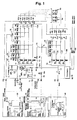
- the mold heating and cooling system pertaining to the present embodiment 1 includes a temperature control apparatus 10 which carries out selectively supplying of steam or warm water as a medium for heating, or cooling water as a medium for cooling to a mold 1 and a mold 2 for a molding machine (A) 8a, and a mold 3 and a mold 4 for a molding machine (B) 8b which mold materials, such as resin for molding; a steam heating unit 30 which feeds steam into the temperature control apparatus 10; a warm water heating unit 35 which feeds warm water into the temperature control apparatus 10; a cooling unit 40 which circulates cooling water; and a mold vacuum system 80 of two-unit configuration that is connected to the temperature control apparatus 10, providing a mold inside cleaning apparatus configured to carry out such processes as vacuuming, bursting, and air blowing for the mold 1 and mold 2 and the mold 3 and mold 4 under the control of the temperature control apparatus 10.
- a temperature control apparatus 10 which carries out selectively supplying of steam or warm water as a medium for heating, or cooling water as a medium for cooling to
- the mold 1 and mold 2 for the molding machine (A) 8a, and the mold 3 and mold 4 for the molding machine (B) 8b include in-mold temperature sensors TC1 to TC4, respectively.
- the steam heating unit 30 changes raw water into soft water with the use of a water softening apparatus 31, and further, using a chemical injection apparatus 32, injects a chemical, such as an antiseptic agent, or the like, into the soft water, before supplying it to a boiler 33 for changing it into steam.
- the boiler 33 for supplies it to an inlet steam valve VSS for the temperature control apparatus 10 from an outlet valve 34.
- the warm water heating unit 35 changes raw water into soft water with the use of a water softening apparatus 31, and further, using a chemical injection apparatus 32, injects a chemical, such as an antiseptic agent, or the like, into the soft water, before supplying it to a warm water generation apparatus 36 to generate warm water.
- the warm water generation apparatus 36 supplies it to the inlet steam valve VSS for the temperature control apparatus 10 from an outlet valve 34.
- the returning warm water from an outlet valve VW provided for the temperature control apparatus 10 is returned to the warm water heating unit 35 through a return valve 37 so as to be capable of discharging to the outside through an outlet valve 37a.
- the cooling unit 40 introduces the cooling water supplied to the cooling water supply port into a cooling tower (or chiller) 41, and further, uses a pump 42 to supply the cooling water heat-exchanged by this cooling tower 41 to a Y-type strainer Y1 provided for the temperature control apparatus 10 through a cooling water outlet port.
- the returning cooling water from an outlet valve VD provided for the temperature control apparatus 10 is caused to flow in from the cooling water return port to be scattered into the inside of the cooling tower 31 from the top thereof for performing heat-exchange.
- the temperature control apparatus 10 includes a heating medium line 11, a cooling medium line 12, an air flow line 13, a warm water outlet medium line 70, an outlet medium line 15 for discharging circulation water (or steam) from the mold 1 to mold 4 toward a cooling unit 40, supply side pipe lines 131 to 134 having a four-line configuration, return side pipe lines 135 to 138 having a four-line configuration, and a control means 50 for carrying out control of this entire multiple heating and cooling system.
- a cooling water reservoir 51, and cooling medium selector valves A1 to A4 are connected, and on the outlet side thereof (on the side of the molding machine (A) 8a and molding machine (B) 8b), supply medium temperature sensors TC5 to TC8 and supply valves VS1 to VS4 are connected.
- the supply valves VS1 and VS2 are connected to the medium inlet of the mold 1 and mold 2 for the molding machine (A) 8a, respectively, while the supply valves VS3 and VS4 are connected to the medium inlet of the mold 3 and mold 4 for the molding machine (B) 8b, respectively.
- return valves VR1 to VR4 and return medium temperature sensors TC9 to TC12 are connected, respectively, while, on the outlet side (on the side of the cooling unit 40), outlet medium selector valves B1 to B4 and a cooling water outlet reservoir 52 are connected.
- Said return valves VR1 and VR2 are connected to the medium outlet of the mold 1 and mold 2, respectively, while the return valves VR3 and VR4 are connected to the medium outlet of the mold 3 and mold 4, respectively.
- the inlet steam valve VSS, a heating medium accumulator reservoir 38 provided with a heating medium temperature sensor TC 14, and heating medium selector valves D1 to D4 are disposed in this order, and the outlet side of these heating medium selector valves D1 to D4 are connected to the supply side pipe lines 131 to 134, respectively.
- the Y-type strainer Y1 In the cooling medium line 12, the Y-type strainer Y1, the pump 19, a water pressure switch WPS, a cooling medium temperature sensor TC 13, and a pressure gage P1 are connected, and this cooling medium line 12 is connected to the cooling water reservoir 51.
- an air supply 22, an air filter 23, an air regulator 24, a check valve CH3, an air accumulator reservoir 29, and a regulating valve 26 are connected in this order. Further, air selector valves E1 to E4, air supply valves VE1 to VE4, and check valves CH5 to CH8 are connected, and further, the outlet sides of these check valves CH5 to CH8 are connected to the supply side pipe lines 131 to 134, respectively, for supplying compressed air.
- an air pressure switch APS and a check valve CH4 are connected for supplying air for valve control to the cooling medium selector valves A1 to A4, the outlet medium selector valves B1 to B4, the return medium selector valves C1 to C4, the heating medium selector valves D1 to D4, and the air selector valves E1 to E4.
- the outlet medium line 15 is constituted by connecting the return medium temperature sensor TC15 and the outlet valve VD to the cooling water outlet reservoir 52 in this order, and connecting this outlet valve VD to the cooling tower 41.
- the warm water outlet medium line 70 is constituted by connecting a warm water bypass valve DB, a warm water selector valve RW, and the outlet valve VW to the heating medium accumulator reservoir 38 in this order, and connecting this outlet valve VW to the return valve 37 in the warm water heating unit 35.
- a check valve CH1 and a silent reducer SH are connected in series.
- a return medium outlet tube 39 is connected, and this return medium outlet tube 39 is connected to a branch section Q between the warm water bypass valve DB and the warm water selector valve RW in the warm water outlet medium line 70.
- a steam selector valve RS in a steam return pipe line 72 between the branch section Q and the silent reducer SH, a steam selector valve RS, a Y-type strainer Y2, and a check valve CH2 are connected.
- the control means 50 includes a program storage section 65 to which a detection temperature signal from the respective in-mold temperature sensors TC1 to TC4 disposed in the molding machine (A) 8a and molding machine (B) 8b is inputted, and in which a temperature determining program is stored; a second temperature determining section 66 in which a second temperature determining program is stored; an MV program storage section 69 in which an MV program for controlling two mold vacuum systems (MV) 80 is stored; a control signal generation section 67 which sends out a control signal to a valve controller 25, the molding machine (A) 8a, and the molding machine (B) 8b; and the valve controller 25 for carrying out open-close control of the respective valves in the temperature control apparatus 10.
- a program storage section 65 to which a detection temperature signal from the respective in-mold temperature sensors TC1 to TC4 disposed in the molding machine (A) 8a and molding machine (B) 8b is inputted, and in which a temperature determining program is stored
- the molding cycle is constituted by the processes of waiting, heating, waiting, cooling, and waiting being performed in this order.
- the temperature determining program in the program storage section 65 determines that the set temperature has been reached, and sends out a determination signal to the control signal generation section 67 for outputting an injection starting signal or mold opening enabling signal to the molding machine (A) 8a and molding machine (B) 8b.
- a second temperature determining program which is stored in said second temperature determining section 66 is operated, and when the second temperature determining program determines that the second temperature setting has been reached, it sends out a determination signal indicating that the second temperature setting has been reached, to the control signal generation section 67 for extending the heating process or the cooling process for the molding machine (A) 8a and the molding machine (B) 8b.
- a filling completion signal or cooling completion signal in the molding process may be sent to the control signal generation section 67 for extending the heating process or the cooling process.
- heating medium is steam
- the steam selector valve RS is opened, and at the start of heating, the outlet medium selector valves B1 to B4, the return medium selector valves C1 to C4, the heating medium selector valves D1 to D4, and the air selector valves E1 to E4 are opened.
- the return medium temperature sensors TC9 to TC12 detect the set temperature (less than 100 deg C )
- the outlet medium selector valves B1 to B4, and the air selector valves E1 to E4 are closed, with the return medium selector valves C1 to C4 and the heating medium selector valves D1 to D4 being kept opened, and the heating process is carried out until an upper limit temperature reaching signal or a heating plus second temperature determining signal, or otherwise, a molding process filling completion signal is inputted.
- the warm selector valve RW is opened, and in the waiting process, only the warm water bypass valve DB is opened, while, in the heating process, the return medium selector valves C1 to C4 and the heating medium selector valves D1 to D4 are opened, and in the cooling process, the cooling medium selector valves A1 to A4, the outlet medium selector valves B1 to B4, and the warm water selector valves RW are opened.
- the steam is passed through the return valves VR1 and VR2, the return medium selector valves C1 and C2, the return medium outlet tube 39, the steam selector valve RS, the Y-type strainer Y2, and the check valve CH2, then being passed through the silent reducer SH with the steam being converted into cooling water, which is returned to the cooling tower 41 through the outlet medium line 15 and the outlet valve VD.
- the cooling water is supplied from the cooling unit 40 to the mold 3 and mold 4 through the V-type strainer Y1, the pump 19, the cooling medium line 12, the pressure gage P1, the cooling water reservoir 51, the cooling medium selector valves A3 and A4, and the supply valve VS3 and VS4 for cooling the mold 3 and mold 4.
- the cooling water which has passed through the mold 3 and mold 4 is passed through the return valves VR3 and VR4, the outlet medium selector valves B3 and B4, the cooling water outlet reservoir 52, and the outlet medium line 15, being returned to the cooling tower 41 after being passed through the outlet valve VD.
- the return medium selector valves C3 and C4 are closed.
- the molding machine (A) 8a having the mold 1 and mold 2 and the molding machine (B) 8b having the mold 3 and mold 4
- the molding machine (A) 8a is to be warmed, warm water is supplied from the warm water heating unit 35 to the mold 1 and mold 2 through the inlet steam valve VSS, the heating medium line 11, the heating medium accumulator reservoir 38, the heating medium selector valves D1 and D2, and the supply valve VS1 and VS2, and is passed through the mold 1 and mold 2 for warming them.
- the warm water is passed through the return valves VR1 and VR2, the return medium selector valves C1 and C2, the return medium outlet tube 39, the warm water selector valve RW, and the warm water outlet medium line 70, and is returned to the warm water generation apparatus 36 after being passed through the outlet valve VW.
- the steam selector valve RS is closed.
- the cooling water is supplied from the cooling unit 40 to the mold 3 and mold 4 through the Y-type strainer Y1, the pump 19, the cooling medium line 12, the pressure gage P1, the cooling water reservoir 51, the cooling medium selector valves A3 and A4, and the supply valves VS3 and VS4 for cooling the mold 3 and mold 4.
- the cooling water which has passed through the mold 3 and mold 4 is passed through the return valves VR3 and VR4, the outlet medium selector valves B3 and B4, the cooling water outlet reservoir 52, and the outlet medium line 15, being returned to the cooling tower 41 after being passed through the outlet valve VD.
- the return medium selector valves C3 and C4 are closed.
- a single temperature control apparatus 10 is placed between two molding machines (the molding machine (A) 8a and the molding machine (B) 8b) such that, with the use of the single temperature control apparatus 10, the two molding machines, i.e., the mold 1 and mold 2 of the molding machine (A) 8a, and the mold 3 and mold 4 of the molding machine (B) 8b can be separately heated, warmed, or cooled, respectively, for carrying out a desired molding operation, even if the molding process for the molding machine (A) 8a and that for the molding machine (B) 8b differ from each other.
- the mold vacuum system 80 includes a suction connection port 91 to be connected to the molds 1 and 2, or the molds 3 and 4, and a suction compression tube 95.
- the mold vacuum system 80 includes an air supply port 81 to which compressed air is supplied from the outside; a filter regulator 82 and a pressure regulating valve 83 which are connected to the air supply port 81 in series; a compressed air tube 92 connected to the pressure regulating valve 83; an inlet valve 84 and a blowback valve 85 which are branch-connected to the outlet side of this compressed air tube 92; a speed controller 87 for flow rate controlling that is connected between this blowback valve 85 and the suction compression tube 95; a suction valve 86 connected to the suction compression tube 95; a compressed air tube 93 connected to the outlet side of the inlet valve 84; a suction tube 94 connected to the suction valve 86; a two-line Venturi tube 88 with a muffler 89 that is commonly connected to the compressed air tube 93 and the suction tube 94; and a suction gage 90 connected to the suction tube 94.
- control for the mold vacuum system 80 is disposed in the control means 50 for the temperature control apparatus 10, including six timers, i.e., a suction delay timer T1, a suction operation timer T2, a burst delay timer T3, a burst operation timer T4, a blow delay timer T5, and a blow operation timer T6.
- the mold vacuum system 80 configured as described above has capabilities of sucking in a volume of air equivalent to that of the cavity of the molds 1 and 2, or the molds 3 and 4 to prevent unsatisfactory molding from being caused; returning the inside pressure condition of the molds 1 and 2, or the molds 3 and 4, which have been vacuumed, to the atmospheric pressure one; and further blowing air to clean the vent hole in the molds 1 and 2, or the molds 3 and 4 every molding cycle.
- Vacuuming suctioning:
- the degree of vacuum in the inside of the molds 1 and 2, or the molds 3 and 4 can be adjusted by pressure setting of the filter regulator 82 connected to the air supply port 81 in the mold vacuum system (MV) 80 (increasing the pressure setting will raise the degree of vacuum, while decreasing the pressure setting will lower the degree of vacuum).
- MV mold vacuum system
- Figure 6 illustrates three different operation modes A, B, and C of the mold vacuum system 80 in terms of the above-described vacuuming, bursting, and air blowing.
- Operation mode A (at the top in Figure 6 ) In this mode, all the vacuuming, bursting, and air blowing processes (consisting of delay and operation periods, respectively) are started from a heating starting signal given by the control means 50 in the temperature control apparatus 10, or an external signal, being carried out with the use of the six timers, i.e., the suction delay timer T1, suction operation timer T2, burst delay timer T3, burst operation timer T4, blow delay timer T5, and blow operation timer T6.
- the suction delay timer T1 suction operation timer T2
- burst delay timer T3 burst operation timer T4
- blow delay timer T5 blow operation timer T6.
- Operation mode B (in the middle of Figure 6 ) In this mode, the vacuuming process (consisting of delay and operation periods) is started from a heating starting signal given by the control means 50 in the temperature control apparatus 10, or an external signal, being carried out with the suction delay timer T1 and suction operation timer T2; and the bursting process and the air blowing process (consisting of delay and operation periods, respectively) are started from a lower limit reaching signal generated by the temperature control apparatus 10, being carried out with the burst delay timer T3, burst operation timer T4, blow delay timer T5, and blow operation timer T6.
- Operation mode C (at the bottom in Figure 6 )
- the vacuuming process (consisting of only an operation period) is started when a temperature difference setting stored in the control means 50 in the temperature control apparatus 10 is reached, and is continued with the use of the suction operation timer T2.
- the temperature difference setting is stored in the control means 50 as a difference computed by subtracting the temperature at which the vacuuming process is to be started, from the upper limit temperature.
- the bursting process and the air blowing process (consisting of delay and operation periods, respectively) are started from a lower limit reaching signal given by the control means 50, being carried out with the use of the burst delay timer T3, burst operation timer T4, blow delay timer T5, and blow operation timer T6.
- the signals for implementing the respective processes of vacuuming, bursting, and air blowing may be issued by a molding machine controller (not shown).
- the timing of start of the respective processes is determined on the basis of the MV program stored in the MV program storage section 69 of the control means 50 in the temperature control apparatus 10 or an external signal.
- the MV program is configured such that it allows use/unuse of the bursting process to be selected, and use/unuse of the air blowing process to be selected.
- the mold multiple heating and cooling system pertaining to the present embodiment 1 provides an outstanding advantage that a single temperature control apparatus 10 is connected to two molding machines (the molding machine (A) 8a and the molding machine (B) 8b). Even if the molding processes for these two molding machines differ from each other, the respective molds 1 and 2, and molds 3 and 4 can be selectively supplied with the necessary steam, warm water, or cooling water, with the required temperature setting being able to be positively provided.
- the temperature control apparatus 10 is required to be connected with only one steam heating unit 30, warm water heating unit 35, and cooling unit 40, whereby the installation space requirement for the entire system can be substantially saved.
- this mold multiple heating and cooling system can be used with no need for a special alteration being made thereto.
- the mold vacuum system 80 of two-unit configuration is used to rapidly suck and discharge the gas and air accumulated in the inside of the respective molds 1 and 2, and molds 3 and 4, whereby gas corrosion, fogging, and short shot can be prevented.
- the vent hole of the molds 1 and 2, and that of the molds 3 and 4, which are easy to be clogged, are cleaned by blowing air every molding cycle, which allows high-quality molded articles to be obtained.
- the mold multiple heating and cooling system pertaining to the present embodiment 2 has basically the same configuration as that of the multiple heating and cooling system of the embodiment 1, however, in place of the molding machine
- the dual-material molding machine 68 is configured such that, on the rear A side of a movable platen 101 including an inversion table 102, a movable platen side part (1st core) 103 which is connected to said inversion table 102 is disposed, while, for the movable platen side part 103, a cavity side part (1st cavity) 104 and a taken-out runner 105 are disposed. Further, a rear cylinder (primary side plasticizing apparatus) 106 which is supported by a stationary platen 107 is disposed for carrying out molding of a molded article 121.
- a rear cylinder primary side plasticizing apparatus
- the dual-material molding machine 68 is configured such that, on the front B side of the movable platen 101, a movable platen side part (2nd core) 113 which is connected to the inversion table 102 is disposed, while, for the movable platen side part 113, a cavity side part (2nd cavity) 114 and a taken-out runner 115 are disposed. Further, a front cylinder (secondary side plasticizing apparatus) 116 which is supported by the stationary platen 107 is disposed for molding a dual-structure molded article 122.
- the temperature control apparatus 10 is connected to the movable platen side part (1st core) 103 and cavity side part (1st cavity) 104, and the movable platen side part (2nd core) 113 and cavity side part (2nd cavity) 114 in the dual-material molding machine 68, as with the molding machine (A) 8a and molding machine (B) 8b as shown in Figure 1 .
- the dual-material molding machine 68 has a position sensor 108 for detecting the positions of the movable platen side part (1st core) 103 and the movable platen side part (2nd core) 113, which change their positions with the inversion table 102 being inverted, and outputting a core position signal.
- the core position signal is a signal that indicates which of the rear A side and the front B side the movable platen side part (1st core) 103 and the movable platen side part (2nd core) 113 are on, respectively.
- the movable platen side part (1st core) 103 and cavity side part (1st cavity) 104, which constitute the mold 8c, and the movable platen side part (2nd core) 113 and cavity side part (2nd cavity) 114, which constitute the mold 8d include in-mold temperature sensors TC 1 to TC4, respectively, as with the molding machine (A) 8a and molding machine (B) 8b in the embodiment 1.
- the molding operation of the mold multiple heating and cooling system pertaining to the embodiment 2 that includes the above-described dual-material molding machine 68 will be described below. Assuming that, as the initial state, the dual-material molding machine 68 does not have a molded article on the rear A side, but already has a molded article 121 on the front B side, the following explanation will be given.
- a core position signal from the position sensor 108 is inputted to the program storage section 65 to be utilized for carrying out the heating process and the cooling process for the mold 8c, 8d in the (d) process of mold clamping and injection in inverted state.
- the movable platen side part (2nd core) 113 which is positioned on the rear A side does not have a molded article, it requires to have a mold temperature of 140 deg C, and thus the steam or warm water is caused to flow through the rear A side for heating it.
- the molding resin is injected from the rear cylinder (primary side plasticizing apparatus) 106, as is the case with the (a) mold clamping and injection, for molding a molded article 121 as shown at bottom of Figure 7 .
- the molding resin is injected from the front cylinder (secondary side plasticizing apparatus) 116 for molding a dual-structure molded article 122 as shown at bottom of Figure 7 .
- the dual-structure molded article 122 is sequentially obtained.
- the temperature setting for the movable platen side part (1st core) 103 and that for the movable platen side part (2nd core) 113 are changed over from one to the other, respectively.
- the mold temperature required for dual-material molding is set for each particular position of the inversion table 102, i.e., for the rear A side and the front B side, respectively.
- the movable platen side part (1st core) 103 is not heated.
- the injection cooling water has been caused to flow after the injection in the previous process, resulting in the movable platen side part (1st core) 103 having been cooled to below a desired temperature, the steam or warm water is caused to flow through this movable platen side part (1st core) 103 for heating it.
- the movable platen side part (2nd core) 113 in said (a) process of mold clamping and injection, and the movable platen side part (1st core) 103 in the (d) process of mold clamping and injection in inverted state can be mentioned.
- a detected temperature signal of the in-mold temperature sensors TC1 to TC4 disposed in the mold 8c and mold 8d is inputted to the program storage section 65, and the temperature determining program determines that the set temperature has been reached, sending out a determination signal to the control signal generation section 67, whereby the control signal generation section 67 outputs an injection starting signal or a mold opening enabling signal to the molds 8c and 8d.
- the second temperature determining section 66 when the temperature determining program determines that the set temperature is reached in the heating process or the cooling process, the second temperature determining program is operated, and when the second temperature determining program determines that the second temperature setting has been reached, it sends out a signal indicating that the second temperature setting has been reached, to the control signal generation section 67 for extending the heating process or the cooling process for the molds 8c and 8d.
- the heating process or the cooling process may be extended by sending out a filling completion signal or a cooling completion signal in the molding machine process to the control signal generation section 67 with no use of the second temperature determining program.
- the operation of the mold vacuum system 80 of two-unit configuration is the same as that in the embodiment 1.
- Figure 9 gives a specific example of combination of the upper limit value and the lower limit value for the temperature of the molds 8c and 8d, thus indicating specific contents of the above-mentioned temperature determining program.
- the same advantages as those of the embodiment 1 can be provided, and in the configuration using the dual-material molding machine 68, the respective temperatures of the molds 8c and 8d that are required for dual-material molding can be exactly set. This allows a high-quality molded article 122 to be obtained, and thus a multiple heating and cooling system using the dual-material molding machine 68 can be established.
- the temperature control apparatus 10 by carrying out the control which combines the temperature determination by the temperature determining program based on the detection signals from the in-mold temperature sensors TC1 to TC4 and said position sensor 108 with that by the second temperature determining program, injection and filling of the resin can be smoothly performed in molding a molded article 122, such as a lens, or any other thick article.
- a molded article 122 having a minimum distortion to be obtained, and further in dual-material molding, a high-quality molded product, such as that which has a lens cover as an integral part, to also be molded.
- the present invention is widely applicable to various forming systems using molds including plural molds besides the above-described two-unit molding machine mold and dual-material molding machine mold.
Landscapes
- Engineering & Computer Science (AREA)
- Mechanical Engineering (AREA)
- Manufacturing & Machinery (AREA)
- Physics & Mathematics (AREA)
- Health & Medical Sciences (AREA)
- Oral & Maxillofacial Surgery (AREA)
- Thermal Sciences (AREA)
- Moulds For Moulding Plastics Or The Like (AREA)
- Molds, Cores, And Manufacturing Methods Thereof (AREA)
- Injection Moulding Of Plastics Or The Like (AREA)
Applications Claiming Priority (1)
| Application Number | Priority Date | Filing Date | Title |
|---|---|---|---|
| JP2008174443A JP2010012682A (ja) | 2008-07-03 | 2008-07-03 | 金型のマルチ加熱冷却システム |
Publications (1)
| Publication Number | Publication Date |
|---|---|
| EP2140996A1 true EP2140996A1 (fr) | 2010-01-06 |
Family
ID=41130435
Family Applications (1)
| Application Number | Title | Priority Date | Filing Date |
|---|---|---|---|
| EP09164396A Withdrawn EP2140996A1 (fr) | 2008-07-03 | 2009-07-02 | Système de refroidissement et de chauffage de plusieurs moules |
Country Status (6)
| Country | Link |
|---|---|
| US (1) | US20100003359A1 (fr) |
| EP (1) | EP2140996A1 (fr) |
| JP (1) | JP2010012682A (fr) |
| KR (1) | KR20100004860A (fr) |
| CN (1) | CN101618579A (fr) |
| TW (1) | TW201006644A (fr) |
Cited By (3)
| Publication number | Priority date | Publication date | Assignee | Title |
|---|---|---|---|---|
| CN105268846A (zh) * | 2015-09-14 | 2016-01-27 | 滁州市成业机械制造有限公司 | 一种水冷效果好的弯折模具 |
| CN109895339A (zh) * | 2018-11-26 | 2019-06-18 | 苏州奥德机械有限公司 | 一种多色模注射成型高光机模温控制系统 |
| CN116921571A (zh) * | 2023-09-15 | 2023-10-24 | 烟台怡和汽车科技有限公司 | 一种车门窗框拉延成型模具及其使用方法 |
Families Citing this family (24)
| Publication number | Priority date | Publication date | Assignee | Title |
|---|---|---|---|---|
| JP2011161776A (ja) * | 2010-02-09 | 2011-08-25 | Dragonjet Corp | 樹脂成形補助システム |
| KR101265126B1 (ko) | 2010-06-23 | 2013-05-16 | (주) 민성정밀 | 금형 온도 제어장치 및 온도 제어방법 |
| CN102019676B (zh) * | 2010-10-29 | 2013-10-09 | 深圳大学 | 蒸汽加热模具的加热设备 |
| CN102029695B (zh) * | 2010-11-15 | 2013-02-06 | 昆山乙盛机械工业有限公司 | 模具急冷急热高光成型工艺 |
| IT1402730B1 (it) * | 2010-11-24 | 2013-09-18 | Ind Frigo Srl | Sistema integrato di preriscaldo e di raffreddamento per stampi |
| GB201211191D0 (en) | 2012-06-25 | 2012-08-08 | Surface Generation Ltd | Tool management system |
| GB201307436D0 (en) | 2013-04-25 | 2013-06-05 | Surface Generation Ltd | Mould tool heat transition management |
| CN103231023B (zh) * | 2013-05-06 | 2016-01-06 | 浙江省机电设计研究院有限公司 | 用于铁型覆砂生产线的铁型自动调温装置和方法 |
| DE102013016755A1 (de) * | 2013-10-10 | 2015-04-16 | Heidelberger Druckmaschinen Ag | Stanzmaschine mit Einrichtung zum Zurichten |
| CN104669490B (zh) * | 2013-11-28 | 2017-04-26 | 安徽中鼎密封件股份有限公司 | 一种硫化罐进气系统及分时进气方法 |
| CN103737882A (zh) * | 2013-12-20 | 2014-04-23 | 昆山易昌泰塑胶有限公司 | 一种改进型急冷急热模具温控装置 |
| CN103707477A (zh) * | 2014-01-07 | 2014-04-09 | 晟扬精密模具(昆山)有限公司 | 注塑模具 |
| JP6345031B2 (ja) * | 2014-08-12 | 2018-06-20 | 株式会社日本製鋼所 | 1台の温度調整装置から熱媒体の供給を受けてヒートアンドクール成形を実施する複数台の射出成形機の運転方法 |
| CN105398081A (zh) * | 2014-09-15 | 2016-03-16 | 江苏锐升新材料有限公司 | 下进上排水压机 |
| CN104275763B (zh) * | 2014-09-24 | 2018-06-12 | 东莞市乔迪麦机械科技有限公司 | 一种发泡制品的热压成型系统 |
| JP6499991B2 (ja) * | 2016-05-13 | 2019-04-10 | 株式会社サーモテック | 温度調節装置 |
| CN107599260A (zh) * | 2017-10-23 | 2018-01-19 | 天津蓝科机械有限公司 | 一种多功能模温机 |
| DE102018001132A1 (de) * | 2018-02-12 | 2019-08-14 | Harburg-Freudenberger Maschinenbau Gmbh | Verfahren und Vorrichtung zur Ventilsteuerung |
| JP7093566B2 (ja) * | 2019-10-09 | 2022-06-30 | 福井精機工業株式会社 | 熱可塑性樹脂成形方法および熱可塑性樹脂成形装置 |
| CN115283619A (zh) * | 2022-08-05 | 2022-11-04 | 徐敏 | 一种合金铸件铸造设备及其铸造方法 |
| CN116728755A (zh) * | 2023-07-14 | 2023-09-12 | 东莞市正文机械有限公司 | 一种用于热压成型机的控制设备及控制方法 |
| CN117400502B (zh) * | 2023-10-31 | 2024-06-14 | 惠州市信友实业有限公司 | 一种注塑机节能控制系统及控制方法 |
| KR102924423B1 (ko) * | 2024-08-30 | 2026-02-06 | (주)아모레퍼시픽 | 화장품 용기의 블로우 성형장치 및 화장품 용기의 블로우 성형방법 |
| US12544963B1 (en) * | 2025-09-05 | 2026-02-10 | Man Woo Heo | Multi-control system of mold cooling structure |
Citations (9)
| Publication number | Priority date | Publication date | Assignee | Title |
|---|---|---|---|---|
| EP0245827A2 (fr) * | 1986-05-12 | 1987-11-19 | BRG Mechatronikai Vállalat | Appareil pour modifier la température de dispositifs, notamment d'outils |
| EP0401872A2 (fr) * | 1986-08-05 | 1990-12-12 | Karl Hehl | Dispositif de changement de moule pour une machine d'injection de matière plastique |
| US5075051A (en) * | 1988-07-28 | 1991-12-24 | Canon Kabushiki Kaisha | Molding process and apparatus for transferring plural molds to plural stations |
| US20030124210A1 (en) * | 2001-12-27 | 2003-07-03 | Toshiba Kikai Kabushiki Kaisha | Injection machine of hierarchical structure type |
| US20030198701A1 (en) * | 2002-04-18 | 2003-10-23 | Toshiba Machine Co., Ltd. | Injection molding apparatus |
| WO2004009323A2 (fr) * | 2002-07-24 | 2004-01-29 | Erik Forsberg | Systeme et procede de fabrication et d'assemblage de contenants steriles |
| US20050167038A1 (en) * | 2004-01-30 | 2005-08-04 | Jarden Corporation | Stacked family molding and subsequent assembly process |
| JP2008023841A (ja) | 2006-07-20 | 2008-02-07 | Hisashi Kojima | 金型の加熱冷却システム、金型の加熱冷却システムに用いるバッファ装置、及び金型の加熱冷却方法 |
| EP2052842A1 (fr) * | 2007-10-23 | 2009-04-29 | Glauco E. Curetti | Processus et système de production d'un conteneur de polymère |
Family Cites Families (7)
| Publication number | Priority date | Publication date | Assignee | Title |
|---|---|---|---|---|
| CA1204262A (fr) * | 1985-08-16 | 1986-05-13 | James S. Sheffield | Dispositif de moulage par injection avec organe de demoulage au gaz sous pression |
| JPH01156808A (ja) * | 1987-12-15 | 1989-06-20 | Sanden Corp | 金型等の冷却システム |
| US5423670A (en) * | 1993-10-08 | 1995-06-13 | Hamel; Julio E. | Enhanced thermal transfer injection molding apparatus |
| US6143215A (en) * | 1996-09-18 | 2000-11-07 | Vec Technology, Inc. | Method and apparatus for molding composite articles |
| US5971742A (en) * | 1996-09-18 | 1999-10-26 | Pyramid Composites Manufacturing Limited Partnership | Apparatus for molding composite articles |
| KR19980072267A (ko) * | 1997-03-03 | 1998-11-05 | 토니헬샴 | 비조질강의 가열.냉각방법 및 그 장치 |
| JP2004006645A (ja) * | 2002-04-19 | 2004-01-08 | Seiko Epson Corp | 圧電体素子の製造方法、圧電体素子並びに液滴吐出式記録ヘッド |
-
2008
- 2008-07-03 JP JP2008174443A patent/JP2010012682A/ja active Pending
-
2009
- 2009-06-10 TW TW098119327A patent/TW201006644A/zh unknown
- 2009-06-18 KR KR1020090054157A patent/KR20100004860A/ko not_active Withdrawn
- 2009-07-02 US US12/497,050 patent/US20100003359A1/en not_active Abandoned
- 2009-07-02 CN CN200910159464A patent/CN101618579A/zh active Pending
- 2009-07-02 EP EP09164396A patent/EP2140996A1/fr not_active Withdrawn
Patent Citations (9)
| Publication number | Priority date | Publication date | Assignee | Title |
|---|---|---|---|---|
| EP0245827A2 (fr) * | 1986-05-12 | 1987-11-19 | BRG Mechatronikai Vállalat | Appareil pour modifier la température de dispositifs, notamment d'outils |
| EP0401872A2 (fr) * | 1986-08-05 | 1990-12-12 | Karl Hehl | Dispositif de changement de moule pour une machine d'injection de matière plastique |
| US5075051A (en) * | 1988-07-28 | 1991-12-24 | Canon Kabushiki Kaisha | Molding process and apparatus for transferring plural molds to plural stations |
| US20030124210A1 (en) * | 2001-12-27 | 2003-07-03 | Toshiba Kikai Kabushiki Kaisha | Injection machine of hierarchical structure type |
| US20030198701A1 (en) * | 2002-04-18 | 2003-10-23 | Toshiba Machine Co., Ltd. | Injection molding apparatus |
| WO2004009323A2 (fr) * | 2002-07-24 | 2004-01-29 | Erik Forsberg | Systeme et procede de fabrication et d'assemblage de contenants steriles |
| US20050167038A1 (en) * | 2004-01-30 | 2005-08-04 | Jarden Corporation | Stacked family molding and subsequent assembly process |
| JP2008023841A (ja) | 2006-07-20 | 2008-02-07 | Hisashi Kojima | 金型の加熱冷却システム、金型の加熱冷却システムに用いるバッファ装置、及び金型の加熱冷却方法 |
| EP2052842A1 (fr) * | 2007-10-23 | 2009-04-29 | Glauco E. Curetti | Processus et système de production d'un conteneur de polymère |
Cited By (4)
| Publication number | Priority date | Publication date | Assignee | Title |
|---|---|---|---|---|
| CN105268846A (zh) * | 2015-09-14 | 2016-01-27 | 滁州市成业机械制造有限公司 | 一种水冷效果好的弯折模具 |
| CN109895339A (zh) * | 2018-11-26 | 2019-06-18 | 苏州奥德机械有限公司 | 一种多色模注射成型高光机模温控制系统 |
| CN116921571A (zh) * | 2023-09-15 | 2023-10-24 | 烟台怡和汽车科技有限公司 | 一种车门窗框拉延成型模具及其使用方法 |
| CN116921571B (zh) * | 2023-09-15 | 2023-12-05 | 烟台怡和汽车科技有限公司 | 一种车门窗框拉延成型模具及其使用方法 |
Also Published As
| Publication number | Publication date |
|---|---|
| TW201006644A (en) | 2010-02-16 |
| KR20100004860A (ko) | 2010-01-13 |
| JP2010012682A (ja) | 2010-01-21 |
| US20100003359A1 (en) | 2010-01-07 |
| CN101618579A (zh) | 2010-01-06 |
Similar Documents
| Publication | Publication Date | Title |
|---|---|---|
| US20100003359A1 (en) | Mold multiple heating and cooling system | |
| US8318061B2 (en) | Mold temperature control circuit of injection molding device and method for discharging heating medium | |
| JP4785479B2 (ja) | 成形装置 | |
| EP3275616B1 (fr) | Dispositif et procédé pour l'aspiration de l'air dans des moules d'injection et l'expulsion ultérieure des pièces moulées | |
| KR100848865B1 (ko) | 열 프레스용 또는 사출성형용 금형의 가열냉각 시스템 및 가열냉각 방법 | |
| JP3144868U (ja) | 金型のマルチ加熱冷却システム | |
| JP2007130613A (ja) | 洗浄装置 | |
| JP2006159643A5 (fr) | ||
| EP1859877B1 (fr) | Dispositif de refroidissement de moule | |
| JP2008105271A (ja) | 過熱蒸気を利用した金型の加熱冷却システム | |
| KR100499881B1 (ko) | 단일진공흡입기로 구성되는 사출성형기 원료공급 시스템및 그 방법 | |
| JP3104023U (ja) | 金型温度調節システム | |
| HK1140166A (en) | Mold multiple heating and cooling system | |
| JP2005254700A (ja) | 金型温度調節システム及び金型温度調節方法 | |
| CN117400502B (zh) | 一种注塑机节能控制系统及控制方法 | |
| JP3116918U (ja) | 成形機システム | |
| JP2017060956A (ja) | 蒸気を加熱媒体とする成形装置およびその被加熱部の流路のドレン除去方法 | |
| JP3128598U (ja) | 過熱蒸気を利用した金型の加熱冷却システム | |
| KR20060051071A (ko) | 열교환기 | |
| WO2008067635A1 (fr) | Système de récupération de fluide d'un système de moulage | |
| CN213830212U (zh) | 一种快速冷却式注塑装置 | |
| JP3109224U (ja) | 熱プレス用の金型の加熱冷却システム | |
| KR20130010145A (ko) | 플라스틱 성형기용 배관 제어 매니폴드 및 그 사용방법 | |
| TWI751018B (zh) | 漿料模塑成型系統及其漿料補給裝置 | |
| CN108000777B (zh) | 一种数字化自动快速成型机及运行方法 |
Legal Events
| Date | Code | Title | Description |
|---|---|---|---|
| PUAI | Public reference made under article 153(3) epc to a published international application that has entered the european phase |
Free format text: ORIGINAL CODE: 0009012 |
|
| AK | Designated contracting states |
Kind code of ref document: A1 Designated state(s): AT BE BG CH CY CZ DE DK EE ES FI FR GB GR HR HU IE IS IT LI LT LU LV MC MK MT NL NO PL PT RO SE SI SK SM TR |
|
| STAA | Information on the status of an ep patent application or granted ep patent |
Free format text: STATUS: THE APPLICATION IS DEEMED TO BE WITHDRAWN |
|
| 18D | Application deemed to be withdrawn |
Effective date: 20100707 |