EP0245916A1 - Appareil et mèthode pour mettre en contact deux éléments avançant continuellement - Google Patents
Appareil et mèthode pour mettre en contact deux éléments avançant continuellement Download PDFInfo
- Publication number
- EP0245916A1 EP0245916A1 EP87301055A EP87301055A EP0245916A1 EP 0245916 A1 EP0245916 A1 EP 0245916A1 EP 87301055 A EP87301055 A EP 87301055A EP 87301055 A EP87301055 A EP 87301055A EP 0245916 A1 EP0245916 A1 EP 0245916A1
- Authority
- EP
- European Patent Office
- Prior art keywords
- medium
- periphery
- rotatable structure
- ribbon
- rotary member
- Prior art date
- Legal status (The legal status is an assumption and is not a legal conclusion. Google has not performed a legal analysis and makes no representation as to the accuracy of the status listed.)
- Granted
Links
- 238000000034 method Methods 0.000 title description 2
- 230000007246 mechanism Effects 0.000 claims description 22
- 239000000463 material Substances 0.000 description 3
- 239000000853 adhesive Substances 0.000 description 2
- 230000001070 adhesive effect Effects 0.000 description 2
- 238000004519 manufacturing process Methods 0.000 description 2
- 230000002093 peripheral effect Effects 0.000 description 2
- 229920003023 plastic Polymers 0.000 description 2
- 230000009471 action Effects 0.000 description 1
- 230000000295 complement effect Effects 0.000 description 1
- 238000010276 construction Methods 0.000 description 1
- 238000009795 derivation Methods 0.000 description 1
- 230000000694 effects Effects 0.000 description 1
- 230000003993 interaction Effects 0.000 description 1
- 238000002372 labelling Methods 0.000 description 1
- 230000008569 process Effects 0.000 description 1
- 230000001105 regulatory effect Effects 0.000 description 1
Images





Classifications
-
- B—PERFORMING OPERATIONS; TRANSPORTING
- B65—CONVEYING; PACKING; STORING; HANDLING THIN OR FILAMENTARY MATERIAL
- B65C—LABELLING OR TAGGING MACHINES, APPARATUS, OR PROCESSES
- B65C9/00—Details of labelling machines or apparatus
- B65C9/26—Devices for applying labels
- B65C9/36—Wipers; Pressers
-
- B—PERFORMING OPERATIONS; TRANSPORTING
- B65—CONVEYING; PACKING; STORING; HANDLING THIN OR FILAMENTARY MATERIAL
- B65C—LABELLING OR TAGGING MACHINES, APPARATUS, OR PROCESSES
- B65C1/00—Labelling flat essentially-rigid surfaces
- B65C1/02—Affixing labels to one flat surface of articles, e.g. of packages, of flat bands
-
- B—PERFORMING OPERATIONS; TRANSPORTING
- B65—CONVEYING; PACKING; STORING; HANDLING THIN OR FILAMENTARY MATERIAL
- B65C—LABELLING OR TAGGING MACHINES, APPARATUS, OR PROCESSES
- B65C1/00—Labelling flat essentially-rigid surfaces
- B65C1/02—Affixing labels to one flat surface of articles, e.g. of packages, of flat bands
- B65C1/025—Affixing labels to one flat surface of articles, e.g. of packages, of flat bands the label being picked up by the article to be labelled, i.e. the labelling head remaining stationary
-
- B—PERFORMING OPERATIONS; TRANSPORTING
- B65—CONVEYING; PACKING; STORING; HANDLING THIN OR FILAMENTARY MATERIAL
- B65C—LABELLING OR TAGGING MACHINES, APPARATUS, OR PROCESSES
- B65C9/00—Details of labelling machines or apparatus
- B65C9/08—Label feeding
- B65C9/18—Label feeding from strips, e.g. from rolls
- B65C9/1865—Label feeding from strips, e.g. from rolls the labels adhering on a backing strip
- B65C9/1869—Label feeding from strips, e.g. from rolls the labels adhering on a backing strip and being transferred directly from the backing strip onto the article
-
- Y—GENERAL TAGGING OF NEW TECHNOLOGICAL DEVELOPMENTS; GENERAL TAGGING OF CROSS-SECTIONAL TECHNOLOGIES SPANNING OVER SEVERAL SECTIONS OF THE IPC; TECHNICAL SUBJECTS COVERED BY FORMER USPC CROSS-REFERENCE ART COLLECTIONS [XRACs] AND DIGESTS
- Y10—TECHNICAL SUBJECTS COVERED BY FORMER USPC
- Y10T—TECHNICAL SUBJECTS COVERED BY FORMER US CLASSIFICATION
- Y10T156/00—Adhesive bonding and miscellaneous chemical manufacture
- Y10T156/17—Surface bonding means and/or assemblymeans with work feeding or handling means
- Y10T156/1702—For plural parts or plural areas of single part
- Y10T156/1705—Lamina transferred to base from adhered flexible web or sheet type carrier
- Y10T156/1707—Discrete spaced laminae on adhered carrier
- Y10T156/171—Means serially presenting discrete base articles or separate portions of a single article
Definitions
- This invention relates to an apparatus for providing a repeating interaction between a first medium and a second medium wherein both mediums are continuously-fed. More particularly, the invention relates to an apparatus that brings two mediums into engagement at the same velocity but results in different spacing between successive engagement points on the two mediums.
- Line production of items sometimes requires that an operation be carried out on the items by bringing a continuous ribbon into engagement with each item as the item passes through an engagement zone with the ribbon.
- a ribbon may carry a detachable material for labelling or decorating the items. If only a short length of the ribbon is utilized for each item and has a dimension less than that of the item, as is usually the case, and if no portion of the length of the continuous ribbon is to be wasted, the ribbon feed rate must be either continuous and at a speed below that of the line or it must be discontinuous, i.e. in a series of discrete steps each at the speed of the line. Both of these arrangements have their disadvantages.
- the mechanism for creating stepped movement of the ribbon is subject to mechanical inefficiency.
- the subject apparatus seeks to overcome such difficulties by allowing the item line and the ribbon to come into engagement when both are continuously-fed at the same speed while also allowing generally all of the length of the ribbon to be utilized.
- the apparatus of the subject invention utilizes a generally circular rotary member and the engagement zone is a position at which the item line extends tangential to the rotary member.
- the ribbon to be brought into engagement with the line of items extends around the circumference of the rotary member and is adapted to move relative to that circumference by a mechanism internal of the rotary member: that mechanism continuously feeds new ribbon to the circumference while withdrawing an equal amount from the circumference.
- the rotation of the rotary member, the feeding and withdrawing of the ribbon from the circumference of the rotary member, and the movement of the item line are such that the ribbon and items on the - line are brought into engagement in the engagement zone while moving at the same speed.
- the engagement is created by a series of engagement members which are fixed to the circumference of the rotary member at equiangular positions. As each engagement member passes through the engagement zone it presses the portion of the ribbon adjacent to it against a respective one of the items moving on the line. It has been found that a certain relationship exists which allows maximum utility to be made of the ribbon. The relationship is between on the one hand the number of engagement members on the rotary member and on the other hand the ratio of the speed of the periphery of the rotary member to the speed of the ribbon. If the rotary member has N engagement members equiangularly positioned on its periphery, then maximum utility of the ribbon occurs when the speed of the ribbon around the rotary member is (N-1)/(N-2) times the peripheral speed of the rotary member.
- the apparatus of the subject invention includes a rotatable structure, a first medium advancement mechanism secured to the rotatable structure so as to rotate with that structure, and a second medium advancement mechanism extending generally tangential-to the rotatable structure at a workstation.
- the rotatable structure has a generally circular periphery to which a series of engagement members are fixed at equiangular positions and along which a first medium is adapted to extend.
- the first medium advancement mechanism is adapted to continuously feed the first medium along the periphery of the rotatable structure in the same direction in which the rotatable structure is adapted to rotate such that the first medium moves at a speed greater than the speed of the adjacent periphery of that rotatable structure.
- the second medium advancement mechanism is adapted to continuously feed a second medium through the workstation at the same speed that the first medium enters the workstation on the periphery of the rotatable structure, the first and second mediums coming into engagement as they pass through the workstation.
- the rotatable structure and the first medium advancement mechanism are adapted to be driven such that the ratio between the speed of the first medium and the speed of the adjacent periphery of the rotatable structure is (N-1)/(N-2) when N engagement members are present on the rotatable structure.
- the first medium advancement mechanism may be secured to the rotatable structure internal of that structure. That mechanism may be driven by a drive linkage means connecting the mechanism to the rotatable structure such that rotation of the rotatable structure advances the first medium along the periphery of that structure, the first medium thereby moving at a speed greater than that of the periphery.
- the first medium advancement mechanism may be comprised of a pair of rollers biased toward each other with the first medium being adapted to extend therebetween.
- the rollers may be rotatably driven by a first drive linkage means connecting the rollers to the rotatable structure such that rotation of the rollers acts to draw the first medium between them, the first medium thereby being pulled along the periphery of the rotatable structure and into that structure.
- the first medium advancement mechanism may also comprise a third roller rotatably driven by a second drive linkage means connecting the third roller to the rotatable structure, the first medium extending around the third roller as that medium leaves the rotatable structure.
- a third roller rotatably driven by a second drive linkage means connecting the third roller to the rotatable structure, the first medium extending around the third roller as that medium leaves the rotatable structure.
- the second medium may be comprised of a continuous medium such as a strip.
- the engagement members may be pads, each pad during its passage through the workstation acting to press the first medium against the second medium.
- the first medium may comprise a releasable portion adapted to adhere to the second medium when the two mediums are pressed together in the workstation and to release itself from the first medium as the two mediums move apart on leaving the workstation.
- Figures 1 to 14 inclusive relate to a "2,3,4" apparatus, those numbers designating that the apparatus has four pads fixed equiangularly to the periphery of the rotary member and that the ratio of the speed of the ribbon passing around the periphery of the rotary member compared to the peripheral speed of the rotary member is in the ratio of 3 to 2.
- the rotary member is designated as 30, each pad is designated as 32, and the ribbon of material that passes around the periphery of the rotary member 30 is designated as 34.
- a driven first spool 36 located inside of rotary member 30 such that its axis of rotation is parallel to that of rotary member 30, takes up ribbon 34 and in so doing draws ribbon 34 around the periphery of rotary member 30.
- a corresponding driven second spool 38 also located inside of rotary member 30 with an axis of rotation parallel to that of rotary member 30, simultaneously provides a corresponding amount of ribbon 34 to the periphery of rotary member 30.
- ribbon 34 is depicted for illustrative purposes only as following a circular path. In actuality, ribbon 34 would extend in a generally chordal pattern between each of the adjacent pairs of pads 32 (see, for instance, Figures 19 and 20).
- Figure 1 illustrates a linefeed 40 moving tangential to rotary member 30 such that each of the four pads 32 apply a slight pressure to items on linefeed 40 as those pads sequentially pass the bottom position on rotary member 30, that bottom position henceforth being called "the workstation" (occupied by position H of rotary member 30 in Figure 1).
- a principle of the operation of the apparatus is that the ribbon 34 passes through the workstation at the same speed at which the linefeed 40 passes through the workstation.
- the periphery of rotary member 30 and the four pads 32 thereon are, however, moving at a slower speed than ribbon 34.
- the difference in the speed of ribbon 34 and each of the pads 32 is created by the continuous action of first spool 36 and second spool 38.
- the desired ratio between the speed of the ribbon and the speed of the rotary member's periphery is 3 to 2; the actual value of those speeds will depend upon the diameter of rotary member 30 and the radial thickness of the pads 32.
- the speed of linefeed 40 is usually fixed by other parameters in a manufacturing facility, and the speed of ribbon 34.on the periphery of rotary member 30 must therefore be matched to that linefeed speed.
- the speed of ribbon 34 is obtained, the diameter and angular speed of rotary member 30 and the number of pads 32. on its periphery are selected so as to obtain the benefits of the invention. Further discussion will be made on these points when the working embodiment is described.
- Figures 1 to 12 inclusive represent twelve sequential one-quarter turns of rotary member 30. Every time one of the pads 32 enters the workstation of the apparatus that pad presses that portion of ribbon 34 temporarily adjacent to it against the item at that time passing through the workstation on linefeed 40, an impression being thereby made on ribbon 34. Since the pad moves through the workstation at a slower speed (two-thirds of the linefeed speed for the 2,3,4 apparatus) than the speed of ribbon 34 it is necessary that the working surface of the pads have a low coefficient of friction. As subsequently described, air may be fed to each pad to reduce the friction between the surface of the pad and the ribbon moving across it.
- Figure 2 illustrates rotary member 30 after it has rotated one-quarter turn clockwise from its position in Figure 1.
- the pad 32 which is at the position F on rotary member 30 in Figure 1 has now entered the workstation and pressed the adjacent portion of ribbon 34 against an item on linefeed 40; a second impression has thereby been created on ribbon 34.
- the portion of ribbon 34 that was in the workstation in Figure 1, and on which the first impression was made, has now entered onto first spool 36; that follows from the fact that ribbon 34 is moving at a speed on the periphery of rotary member 30 that is 1.5 times as great as the speed of the periphery (and thus the pads 32) of rotary member 30.
- the pad 32 at position D of rotary member 30 has entered the workstation and made a third impression on the ribbon 34.
- that portion of ribbon 34 bearing the second impression i.e. that created by the pressure of pad 32 at position F in Figure 2
- the position of that second impression is indicated by the arrow having the adjacent numeral 2; every such arrow in the figures points to an impression made by one of the pads 32 on ribbon 34, the number beside the impression indicating the order of its creation.
- Figures 4 to 12 illustrate the impressions made on ribbon 34 by the following nine one-quarter turns of rotary member 30.
- the pad 32 at position B on rotary member 30 is creating a fourth impression on ribbon 34, while the second and third impressions (made by the pads 32 at positions F and D in Figures 2 and 3, respectively) are still present on that portion of ribbon 34 extending around the periphery of rotary member 30.
- the second impression has disappeared, that impression having been wound onto first spool 36.
- Figure 13 represents the impressions that one would see if they removed the ribbon 34 surrounding rotary member 30 immediately after the ribbon has been impacted by the adjacent pad in the workstation in each of the Figures 1 to 12.
- the second ribbon from the top in Figure 13 has a circled 2 directly under the letter F.
- the impression made by pad 32 in Figure 1 is not present since that part of ribbon 34 has moved off of the periphery of rotary member 30 and onto first spool 36.
- the difference between each successive portion of ribbon 34 illustrated is a movement of one position to the left.
- impressions 6 and 7 are in their expected positions when it is considered that those impressions are separated by three parts of ribbon 34 and that that ribbon itself is moving left with each successive portion illustrated in Figure 13.
- the ninth impression is made on ribbon 34 just prior to that position on ribbon 34 being wound onto first spool 36.
- the thirteenth impression on ribbon 34 would be the next impression to follow the pattern set by the fifth and ninth impression.
- the seventh portion of ribbon 34 has four impressions on it in the same positions as those on the eleventh portion of ribbon 34.
- the eighth portion of ribbon 34 illustrated in Figure 13 has impressions made in the same positions as the impressions on the twelfth portion of ribbon 34 illustrated in that figure. That can also be seen by comparing Figure 7 with Figure 11 and by comparing Figure 8 with Figure 12. If further portions of ribbon 34 were illustrated (the thirteenth and succeeding portions), they would all bear a repeating pattern with the impressions illustrated on portions 7, 8, 9, and 10 of ribbon 34 in Figure 13.
- Figure 14 illustrates the impressions that would be seen on ribbon 34 if, after twelve impressions had been made on that ribbon, the ribbon were removed from the periphery of rotary member 30 and from first spool 36, and were then laid out flat.
- the thirteenth impression had been made, it would have been made between the tenth and eighth impression.
- the fourteenth impression would then have been made after the eleventh impression.
- the fifteenth impression would then follow the twelfth impression.
- the sixteenth impression would then follow in the third space after the fifteenth impression, and the seventeenth impression would be made in the space between the thirteenth impression and the twelfth impression.
- the effect is that ribbon 34 is essentially filled with impressions during steady-state operation of the apparatus and a maximum use of the surface area of ribbon 34 is obtained.
- Figures 15, 16 and 17 relate to a "3,4,5" apparatus.
- Rotary member 50 has five pads 52 fixed at equiangular positions around its periphery.
- a ribbon 54 extends around the periphery of rotary member 50, first spool 56 collecting ribbon 54 from the periphery of rotary member 50, and second spool 58 adding a compensating amount of ribbon 54 to that periphery.
- the speed of ribbon 54 is 4/3 times the speed of the outside surface of each pad 52.
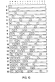
- Figure 16 represents 20 successive views of the portion of ribbon 54 present on the periphery of rotary member 50, each view being taken immediately after the impression having the corresponding number was made on ribbon 54.
- Figure 16 can be seen to be analogous to Figure 13, except that the steady-state condition is not achieved until the thirteenth impression, with portions 13, 14, 15, 16 and 17 representing the repeating pattern for the 3,4,5 apparatus.
- Figure 17 can similarly be seen to be analogous to Figure 14.
- Figures 14 and 17 can be seen to be equivalent to row H of Figure 13 and row 0 of Figure 16 respectively.
- Figure 18 is intended to illustrate the relationship between, on the one hand, a series of N pads 70 equiangularly positioned on the periphery of a rotary member, and on the other hand, the impressions made on a ribbon 72 extending around the periphery of the rotary member.
- S represents the number of spaces between the corresponding positions on successive pads 70 on the periphery of the rotary member
- S+l the number of spaces between successive impressions on ribbon 72.
- Rotary member 50 has 15 equiangular positions on its periphery, and for each one-fifth turn of rotary member 50 ribbon 54 moves through a four-fifteenths turn on its periphery.
- impression 1 on ribbon 72 the subsequent impressions on ribbon 72 become more and more advanced relative to the corresponding pads 70. Not only do the impressions on the ribbon move increasingly away from their corresponding pad, but they are also continuously moving toward the next pad. For instance, impression 2 on ribbon 72 is just one space advanced on the position of pad 2, but impression 5 has advanced a further three spaces relative to pad 5.
- the compensating factor for the advancing movement of the impressions on ribbon 72 relative to the corresponding pads is the continuous withdrawal of spaces on ribbon 72 from the periphery of the rotary member; for each S spaces on ribbon 72 that pass through the workstation, one space is pulled into the rotary member.
- N impressions on ribbon 72 occupy NS+S+2, i.e. (N+I)S+2 spaces on that strip.
- a certain amount of ribbon 72 is, however, pulled into the rotary member during one full completion of that rotary member, and we equate the amount of ribbon 72 pulled into the rotary member during that one full rotation as equivalent to the spaces occupied by impression 1, impression 2, and all of the spaces on ribbon 72 between those two impressions. That allows impression N on ribbon 72 to correspond with the space after impression 2 on that ribbon.
- a relationship can be derived between N and S to place impression N in the space immediately following impression 2.
- FIG 19 illustrates, in perspective view, the working embodiment of the apparatus of the invention.
- a rotary member 80 is formed by a circular plate 82 which is mounted on a hollow axle 84, that hollow axle in turn being rotatably mounted by a bearing (not shown) to vertical wall member 86.
- Rotary member 80 is also comprised by an annular member 88 of rectangular cross-section, that annular member extending around the periphery of circular plate 82 and having a small opening for a purpose that will subsequently become more obvious.
- a motor 90 mounted to the backside of vertical wall 86, has a sprocket connected by a chain drive to a sprocket mounted concentrically on hollow axle 84; rotary member 80 can thereby be rotated at a selective speed.
- a continuous strip 96 of material is pulled through the workstation while being supported on a shelf 98 which is itself supported by vertical wall member 86.
- Strip 96 represents a series of discrete printed images which have been printed but not separated.
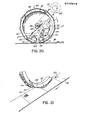
- the apparatus is utilized to place a transparent plastic layer over a coded mark 100 formed on each image by a pigmented adhesive. As can be seen in Figures 19 and 21, the marks 100 are proximate of the same corner on each of the printed images.
- the marks 100 are in the plane defined by annular member 88 and ribbon 94. As each mark 100 enters the workstation on strip 96, a corresponding pad 92 on rotary member 80 presses the adjacent part of ribbon 94 against that mark. A transparent transfer layer is held to the backing portion of ribbon 94 by a "release layer". Upon leaving the workstation, a segment of the transfer layer of ribbon 94 having a contour matching mark 100 is sheared away from the backing portion of ribbon 94.
- Figure 21 illustrates mark 101 on sheet 96, mark 101 being comprised of a pigmented adhesive mark 100 covered by a portion of the transfer layer of ribbon 94; a complementary image can be seen to be formed in ribbon 94 by the missing portion of the transfer layer.
- Each of the printed images on strip 96 is six inches long. Since the ribbon 94 moves at a speed (S+1)/S, i.e. (N-1)/(N-2), times greater than the speed of the pads 92, the approximate circumference of rotary member 80 (to the outside of each pad 92) is: For a 14,15,16 apparatus, for example, the circumference would amount to approximately 89.6 inches which is equivalent to a diameter of approximately 28.5 inches. The diameter of the wheel can also be calculated for rotary members having other numbers of pads equiangularly positioned around their circumferences. For purposes of the printed image marking, a 9,10,11 apparatus was selected. In other words, the apparatus has 11 pads 92 equiangularly positioned around rotary member 80.
- Rotary member 80 has a circumference of approximately 59.4 inches and a diameter (to the outside of the pads 92) of approximately 18.9 inches.
- Strip 96 is fed from other equipment at a rate of 240 feet per minute, i.e. 480 uncut printed images per minute. Therefore, ribbon 94 must . enter the workstation at 240 feet per minute. Also, each pad 92 must enter the workstation at (9/10)X(240) feet/minute, or 216 feet per minute. Since the diameter of rotary member 80 for the 9,10,11 apparatus has been previously calculated, the rotational speed of rotary member 80 can be calculated.
- An accurately-made chain 105 can then be connected between the sprocket on motor 90 and the sprocket on the hollow axle 84 of rotary member 80. The speed of motor 90 is adjusted to exactly set the requisite speed at which each of the pads 92 enter the workstation.
- a fresh roll of the ribbon 94 is mounted on a spool 110, that spool being large enough to hold approximately a four-hour supply of ribbon 94.
- a pair of rollers 111 and 112 are drive linked by meshing sprockets 113 and 114, respectively, so as to turn at the same speed in opposite directions. Rollers 111 and 112 are biased toward each other by a spring 115 having its end connected to a pair of bushings sitting on the axles of rollers 111 and 112.
- the axle of roller 112 is mounted in a slot in plate 82 such that roller 112 is capable of a slight sliding movement.
- Chain 116 extends around a sprocket on the axle of the roller 111 and also around a sprocket connected to hollow axle 84.
- Chain 117 extends around a sprocket on the axle of roller 112 and also around a sprocket on the axle of spool 110.
- the ribbon 94 After leaving the periphery of rotary member 80, the ribbon 94 passes around a roller 118 at the opening in annular member 88, as shown in Figure 20. After passing around roller 118, ribbon 94 is pulled between the rollers 111 and 112. It then passes around a further roller 119 before passing partially around the outside of the fresh roll of ribbon 94 on spool 110 and out through the center of hollow axle 84. The fresh supply of ribbon 94 passes around a pair of rollers 120 and 121, then around a roller 122 at the opening in annular member 88, and then onto the periphery of rotary member 80. A suction device (not shown) sits behind the apparatus and pulls ribbon 94 through the centre of hollow axle 84.
- a self-governing means is utilized to maintain proper tension on ribbon 94 as it passes around rotary member 80.
- rollers 111 and 112 pull used ribbon 94 into rotary member 80 let us assume that the tension increases on that portion of ribbon 94 extending around the periphery. In that case, the portion of ribbon 94 extending around driven roller 121 is pulled more tightly against that roller and slides less on that roller; that portion of ribbon 94 is thereby fed onto the periphery of rotary member 80, i.e. enters at a speed higher than normal. Once the tension is thereby reduced on ribbon 94 on that periphery, ribbon 94 is no longer pulled as tightly against roller 121 and is no longer fed onto the periphery.
- Each of the four driven rollers 110, 111, 112 and 121 are connected together by sprockets and accurately-made chains, 116, 117 and 123, all of those rollers being in turn driven through a second sprocket on hollow axle 84.
- the position of the chains connecting the four rollers together and to hollow axle 84 are shown in outline on Figure 20.
- Figure 23 illustrates an air bearing that may be employed at each pad to reduce the friction between the surface of the pad and the ribbon.
- Air is pumped to an annular plenum 130 extending internally around the periphery of the rotary member.
- Hose 131 which feeds air to plenum 130, rotates with the rotary member and is connected by a known type of rotary joint (not shown) to an air plenum on the rotational axis of the rotary member.
- Pad 132 is secured to the annular member 133 of the rotary member by a bolt 134.
- a series of passages 135 in the pad 132 and a passage 136 in annular member 133 direct air in plenum 130 to the surface of pad 132.
- An air cushion is thereby created between pad 132 and ribbon 137.
- Element 138 shown in Figure 23 is a portion of the circular plate of the rotary member.
Landscapes
- Labeling Devices (AREA)
- Vehicle Body Suspensions (AREA)
- Spinning Or Twisting Of Yarns (AREA)
- Automatic Analysis And Handling Materials Therefor (AREA)
- Specific Conveyance Elements (AREA)
- Massaging Devices (AREA)
- Processing Of Meat And Fish (AREA)
Priority Applications (1)
| Application Number | Priority Date | Filing Date | Title |
|---|---|---|---|
| AT87301055T ATE57151T1 (de) | 1986-02-19 | 1987-02-06 | Vorrichtung und verfahren in zwei kontinuierlich bewegte elemente in kontakt zu bringen. |
Applications Claiming Priority (2)
| Application Number | Priority Date | Filing Date | Title |
|---|---|---|---|
| CA000502160A CA1268737A (fr) | 1986-02-19 | 1986-02-19 | Mecanisme de transfert homocinetique |
| CA502160 | 1986-02-19 |
Publications (2)
| Publication Number | Publication Date |
|---|---|
| EP0245916A1 true EP0245916A1 (fr) | 1987-11-19 |
| EP0245916B1 EP0245916B1 (fr) | 1990-10-03 |
Family
ID=4132494
Family Applications (1)
| Application Number | Title | Priority Date | Filing Date |
|---|---|---|---|
| EP87301055A Expired - Lifetime EP0245916B1 (fr) | 1986-02-19 | 1987-02-06 | Appareil et mèthode pour mettre en contact deux éléments avançant continuellement |
Country Status (5)
| Country | Link |
|---|---|
| US (1) | US4770736A (fr) |
| EP (1) | EP0245916B1 (fr) |
| AT (1) | ATE57151T1 (fr) |
| CA (1) | CA1268737A (fr) |
| DE (1) | DE3765308D1 (fr) |
Families Citing this family (2)
| Publication number | Priority date | Publication date | Assignee | Title |
|---|---|---|---|---|
| US5520763A (en) * | 1992-02-03 | 1996-05-28 | Moore Business Forms, Inc. | Intelligent foil transfer |
| US6516854B1 (en) * | 2000-11-21 | 2003-02-11 | Behavior Tech Corporation | Automatic label-sticking device for optical disc drive |
Citations (1)
| Publication number | Priority date | Publication date | Assignee | Title |
|---|---|---|---|---|
| DE3040934C2 (de) * | 1980-10-28 | 1982-07-01 | Siemens AG, 1000 Berlin und 8000 München | Verfahren zum Kennzeichnen von langgestrecktem Gut |
Family Cites Families (13)
| Publication number | Priority date | Publication date | Assignee | Title |
|---|---|---|---|---|
| US3690252A (en) * | 1969-11-20 | 1972-09-12 | Xerox Corp | Lithographic inking apparatus |
| US3943023A (en) * | 1971-05-21 | 1976-03-09 | Commercial Decal, Inc. | Automatic decal transfer method and apparatus therefor |
| US3833448A (en) * | 1972-09-08 | 1974-09-03 | Burroughs Corp | Apparatus for automatically attaching a magnetizable, machine readable stripe to a commercial document |
| US4113538A (en) * | 1976-08-24 | 1978-09-12 | Green Russell W | Method of and means for mounting labels |
| US4328061A (en) * | 1977-10-25 | 1982-05-04 | Haggar Company | Apparatus for depositing adhesive strips |
| US4288281A (en) * | 1978-09-28 | 1981-09-08 | Sigma Corporation | Appliance for adhering a sensing marker on a medium for recording information |
| US4333781A (en) * | 1980-02-19 | 1982-06-08 | Meulenberg Daniel R | Method and apparatus for manufacturing decals |
| US4350555A (en) * | 1980-07-10 | 1982-09-21 | Keuffel & Esser Company | Precision laminating press |
| DE3029521A1 (de) * | 1980-08-04 | 1982-03-04 | Helmuth 2058 Lauenburg Schmoock | Schaltung mit aufgedruckten leiterbahnen und verfahren zu deren herstellung |
| US4342614A (en) * | 1981-03-03 | 1982-08-03 | Minnesota Mining And Manufacturing Company | Pressure applicator for graphic transfer |
| US4451318A (en) * | 1981-09-21 | 1984-05-29 | Haggar Company | System for prefabricating pocket welts and facing strips |
| JPS59104649A (ja) * | 1982-12-08 | 1984-06-16 | Somar Corp | 保護膜の剥離装置 |
| US4557783A (en) * | 1983-12-05 | 1985-12-10 | Cincinnati Milacron Inc. | Composite tape laying machine and method |
-
1986
- 1986-02-19 CA CA000502160A patent/CA1268737A/fr not_active Expired - Fee Related
- 1986-11-05 US US06/927,798 patent/US4770736A/en not_active Expired - Fee Related
-
1987
- 1987-02-06 DE DE8787301055T patent/DE3765308D1/de not_active Expired - Fee Related
- 1987-02-06 EP EP87301055A patent/EP0245916B1/fr not_active Expired - Lifetime
- 1987-02-06 AT AT87301055T patent/ATE57151T1/de not_active IP Right Cessation
Patent Citations (1)
| Publication number | Priority date | Publication date | Assignee | Title |
|---|---|---|---|---|
| DE3040934C2 (de) * | 1980-10-28 | 1982-07-01 | Siemens AG, 1000 Berlin und 8000 München | Verfahren zum Kennzeichnen von langgestrecktem Gut |
Also Published As
| Publication number | Publication date |
|---|---|
| ATE57151T1 (de) | 1990-10-15 |
| EP0245916B1 (fr) | 1990-10-03 |
| US4770736A (en) | 1988-09-13 |
| CA1268737A (fr) | 1990-05-08 |
| DE3765308D1 (de) | 1990-11-08 |
Similar Documents
| Publication | Publication Date | Title |
|---|---|---|
| US5344519A (en) | Apparatus for applying labels onto small cylindrical articles having improved vacuum and air pressure porting for label transport drum | |
| DE69400855T2 (de) | Vorrichtung und Verfahren zum Etikettieren von kleinen, zylindrischen Gegenständen | |
| US4650536A (en) | Machine for applying a portion of photosensitive film to at least one face of a flat plate having a surface area greater than said portion | |
| CN1118911A (zh) | 标签及其制法 | |
| EP0855963A4 (fr) | Appareil de decoration a transfert d'encre par effet thermique | |
| DE3022525A1 (de) | Verfahren und vorrichtung zum automatischen aufbringen von aufklebern auf eine endlosbahn | |
| US4715758A (en) | Method and apparatus for attaching sheets together | |
| EP0245916B1 (fr) | Appareil et mèthode pour mettre en contact deux éléments avançant continuellement | |
| US4084501A (en) | Printing machine for printing groups of symbols | |
| CN1163359C (zh) | 一种多色印刷设备及彩色印刷方法 | |
| US5401353A (en) | Apparatus and method for applying labels onto small cylindrical articles using static wipers | |
| US4504336A (en) | Tab applying method and apparatus | |
| US3147969A (en) | Collating machine | |
| US3808969A (en) | Replicating apparatus with locking means | |
| US4813350A (en) | Mechanical printer for numbering continuous forms | |
| EP0283750A2 (fr) | Appareil pour détacher des articles adhérant à une bande | |
| US3713420A (en) | Web printing means | |
| EP0810172A3 (fr) | Appareil à fabriquer des rouleaux pour bandes continues ou enchevêtrées | |
| EP0222446A2 (fr) | Procédé pour appliquer une partie d'une pellicule photosensible sur au moins un côté d'une plaque plane ayant une surface plus grande que ladite partie | |
| JPH04507225A (ja) | 剥離可能な箔を移動ウェブに転写する為の方法および装置 | |
| CN2087563U (zh) | 电缆技术标志、长度连续打印机 | |
| CA1084826A (fr) | Appareil pour fabriquer des cylindres en papier pour proteger les jeunes pousses | |
| US4425847A (en) | Traveling pressure pad assembly for mechanical printer apparatus | |
| US2998153A (en) | Machine for attaching gummed labels to envelopes and the like | |
| DE2064183C3 (de) | Handetikettiergerät |
Legal Events
| Date | Code | Title | Description |
|---|---|---|---|
| PUAI | Public reference made under article 153(3) epc to a published international application that has entered the european phase |
Free format text: ORIGINAL CODE: 0009012 |
|
| AK | Designated contracting states |
Kind code of ref document: A1 Designated state(s): AT BE CH DE ES FR GB GR IT LI LU NL SE |
|
| 17P | Request for examination filed |
Effective date: 19880513 |
|
| 17Q | First examination report despatched |
Effective date: 19890516 |
|
| GRAA | (expected) grant |
Free format text: ORIGINAL CODE: 0009210 |
|
| AK | Designated contracting states |
Kind code of ref document: B1 Designated state(s): AT BE CH DE ES FR GB GR IT LI LU NL SE |
|
| PG25 | Lapsed in a contracting state [announced via postgrant information from national office to epo] |
Ref country code: GR Free format text: LAPSE BECAUSE OF FAILURE TO SUBMIT A TRANSLATION OF THE DESCRIPTION OR TO PAY THE FEE WITHIN THE PRESCRIBED TIME-LIMIT Effective date: 19901003 Ref country code: AT Effective date: 19901003 Ref country code: NL Effective date: 19901003 Ref country code: SE Effective date: 19901003 Ref country code: FR Effective date: 19901003 Ref country code: LI Effective date: 19901003 Ref country code: BE Effective date: 19901003 Ref country code: CH Effective date: 19901003 Ref country code: IT Free format text: LAPSE BECAUSE OF FAILURE TO SUBMIT A TRANSLATION OF THE DESCRIPTION OR TO PAY THE FEE WITHIN THE PRE;WARNING: LAPSES OF ITALIAN PATENTS WITH EFFECTIVE DATE BEFORE 2007 MAY HAVE OCCURRED AT ANY TIME BEFORE 2007. THE CORRECT EFFECTIVE DATE MAY BE DIFFERENT FROM THE ONE RECORDED.SCRIBED TIME-LIMIT Effective date: 19901003 |
|
| REF | Corresponds to: |
Ref document number: 57151 Country of ref document: AT Date of ref document: 19901015 Kind code of ref document: T |
|
| REF | Corresponds to: |
Ref document number: 3765308 Country of ref document: DE Date of ref document: 19901108 |
|
| PG25 | Lapsed in a contracting state [announced via postgrant information from national office to epo] |
Ref country code: ES Free format text: LAPSE BECAUSE OF FAILURE TO SUBMIT A TRANSLATION OF THE DESCRIPTION OR TO PAY THE FEE WITHIN THE PRESCRIBED TIME-LIMIT Effective date: 19910114 |
|
| REG | Reference to a national code |
Ref country code: CH Ref legal event code: PL |
|
| PG25 | Lapsed in a contracting state [announced via postgrant information from national office to epo] |
Ref country code: GB Effective date: 19910206 |
|
| EN | Fr: translation not filed | ||
| PG25 | Lapsed in a contracting state [announced via postgrant information from national office to epo] |
Ref country code: LU Free format text: LAPSE BECAUSE OF NON-PAYMENT OF DUE FEES Effective date: 19910228 |
|
| NLV1 | Nl: lapsed or annulled due to failure to fulfill the requirements of art. 29p and 29m of the patents act | ||
| PLBE | No opposition filed within time limit |
Free format text: ORIGINAL CODE: 0009261 |
|
| STAA | Information on the status of an ep patent application or granted ep patent |
Free format text: STATUS: NO OPPOSITION FILED WITHIN TIME LIMIT |
|
| 26N | No opposition filed | ||
| GBPC | Gb: european patent ceased through non-payment of renewal fee | ||
| PG25 | Lapsed in a contracting state [announced via postgrant information from national office to epo] |
Ref country code: DE Effective date: 19911101 |