EP0246375A1 - Assemblage tête/bras et mécanisme d'accès rotatif pour mémoire à disques - Google Patents
Assemblage tête/bras et mécanisme d'accès rotatif pour mémoire à disques Download PDFInfo
- Publication number
- EP0246375A1 EP0246375A1 EP86303939A EP86303939A EP0246375A1 EP 0246375 A1 EP0246375 A1 EP 0246375A1 EP 86303939 A EP86303939 A EP 86303939A EP 86303939 A EP86303939 A EP 86303939A EP 0246375 A1 EP0246375 A1 EP 0246375A1
- Authority
- EP
- European Patent Office
- Prior art keywords
- head
- arm
- arm assembly
- counterweight
- actuator
- Prior art date
- Legal status (The legal status is an assumption and is not a legal conclusion. Google has not performed a legal analysis and makes no representation as to the accuracy of the status listed.)
- Granted
Links
- 230000007246 mechanism Effects 0.000 title claims abstract description 10
- 230000002463 transducing effect Effects 0.000 claims abstract description 7
- OKTJSMMVPCPJKN-UHFFFAOYSA-N Carbon Chemical compound [C] OKTJSMMVPCPJKN-UHFFFAOYSA-N 0.000 claims description 3
- 229910052799 carbon Inorganic materials 0.000 claims description 3
- 239000013536 elastomeric material Substances 0.000 claims description 3
- HQQADJVZYDDRJT-UHFFFAOYSA-N ethene;prop-1-ene Chemical group C=C.CC=C HQQADJVZYDDRJT-UHFFFAOYSA-N 0.000 claims description 3
- 230000000295 complement effect Effects 0.000 claims description 2
- 238000005304 joining Methods 0.000 claims description 2
- 230000010355 oscillation Effects 0.000 claims description 2
- 230000001419 dependent effect Effects 0.000 claims 1
- 230000006870 function Effects 0.000 abstract description 20
- 238000013016 damping Methods 0.000 description 26
- 238000000429 assembly Methods 0.000 description 6
- 239000000725 suspension Substances 0.000 description 6
- 230000000694 effects Effects 0.000 description 5
- 238000003860 storage Methods 0.000 description 5
- 230000000712 assembly Effects 0.000 description 4
- 230000005291 magnetic effect Effects 0.000 description 4
- 239000000463 material Substances 0.000 description 3
- 238000000034 method Methods 0.000 description 3
- 239000004411 aluminium Substances 0.000 description 2
- 229910052782 aluminium Inorganic materials 0.000 description 2
- XAGFODPZIPBFFR-UHFFFAOYSA-N aluminium Chemical compound [Al] XAGFODPZIPBFFR-UHFFFAOYSA-N 0.000 description 2
- 230000004907 flux Effects 0.000 description 2
- 239000006096 absorbing agent Substances 0.000 description 1
- 230000001133 acceleration Effects 0.000 description 1
- 239000002390 adhesive tape Substances 0.000 description 1
- 238000005452 bending Methods 0.000 description 1
- 230000015556 catabolic process Effects 0.000 description 1
- 229940000425 combination drug Drugs 0.000 description 1
- 238000010276 construction Methods 0.000 description 1
- 238000006731 degradation reaction Methods 0.000 description 1
- 230000002939 deleterious effect Effects 0.000 description 1
- 230000009977 dual effect Effects 0.000 description 1
- 230000009477 glass transition Effects 0.000 description 1
- 238000011065 in-situ storage Methods 0.000 description 1
- 238000004519 manufacturing process Methods 0.000 description 1
- 229910052751 metal Inorganic materials 0.000 description 1
- 239000002184 metal Substances 0.000 description 1
- 230000003287 optical effect Effects 0.000 description 1
- 235000012771 pancakes Nutrition 0.000 description 1
- 230000009467 reduction Effects 0.000 description 1
- 230000035939 shock Effects 0.000 description 1
- 230000003068 static effect Effects 0.000 description 1
- 239000010409 thin film Substances 0.000 description 1
- 238000004804 winding Methods 0.000 description 1
Images



Classifications
-
- G—PHYSICS
- G11—INFORMATION STORAGE
- G11B—INFORMATION STORAGE BASED ON RELATIVE MOVEMENT BETWEEN RECORD CARRIER AND TRANSDUCER
- G11B5/00—Recording by magnetisation or demagnetisation of a record carrier; Reproducing by magnetic means; Record carriers therefor
- G11B5/48—Disposition or mounting of heads or head supports relative to record carriers ; arrangements of heads, e.g. for scanning the record carrier to increase the relative speed
- G11B5/4806—Disposition or mounting of heads or head supports relative to record carriers ; arrangements of heads, e.g. for scanning the record carrier to increase the relative speed specially adapted for disk drive assemblies, e.g. assembly prior to operation, hard or flexible disk drives
- G11B5/4833—Structure of the arm assembly, e.g. load beams, flexures, parts of the arm adapted for controlling vertical force on the head
-
- G—PHYSICS
- G11—INFORMATION STORAGE
- G11B—INFORMATION STORAGE BASED ON RELATIVE MOVEMENT BETWEEN RECORD CARRIER AND TRANSDUCER
- G11B5/00—Recording by magnetisation or demagnetisation of a record carrier; Reproducing by magnetic means; Record carriers therefor
- G11B5/48—Disposition or mounting of heads or head supports relative to record carriers ; arrangements of heads, e.g. for scanning the record carrier to increase the relative speed
- G11B5/54—Disposition or mounting of heads or head supports relative to record carriers ; arrangements of heads, e.g. for scanning the record carrier to increase the relative speed with provision for moving the head into or out of its operative position or across tracks
- G11B5/55—Track change, selection or acquisition by displacement of the head
- G11B5/5521—Track change, selection or acquisition by displacement of the head across disk tracks
-
- G—PHYSICS
- G11—INFORMATION STORAGE
- G11B—INFORMATION STORAGE BASED ON RELATIVE MOVEMENT BETWEEN RECORD CARRIER AND TRANSDUCER
- G11B5/00—Recording by magnetisation or demagnetisation of a record carrier; Reproducing by magnetic means; Record carriers therefor
- G11B5/48—Disposition or mounting of heads or head supports relative to record carriers ; arrangements of heads, e.g. for scanning the record carrier to increase the relative speed
- G11B5/54—Disposition or mounting of heads or head supports relative to record carriers ; arrangements of heads, e.g. for scanning the record carrier to increase the relative speed with provision for moving the head into or out of its operative position or across tracks
- G11B5/55—Track change, selection or acquisition by displacement of the head
- G11B5/5521—Track change, selection or acquisition by displacement of the head across disk tracks
- G11B5/5582—Track change, selection or acquisition by displacement of the head across disk tracks system adaptation for working during or after external perturbation, e.g. in the presence of a mechanical oscillation caused by a shock
Definitions
- the present invention relates to head/arm assemblies for disk files and to rotary access mechanisms comprising such assemblies in combination with a rotary actuator.
- the disk file in which information is written on and reproduced from the surface of a rotating disk record medium by means of a transducing head.
- the disk media may be rigid or flexible and the storage effect may be, for example, optical or magnetic. It is common, particularly in magnetic recording, to support the transducing head very close to the disk medium by means of an air bearing created by the motion of the disk.
- linear or rotary head positioning apparatus to move the heads over the disk surface to different radial positions.
- the heads are supported over the disk surface by means of support arms mounted on the positioning apparatus in cantilever fashion.
- the heads are mounted on the support arms by means of compliant suspensions which allow limited motion of the heads to accommodate irregularities in the disk surface or variations in the air bearing. Together the head/arm assemblies and the positioning apparatus constitute an access mechanism for accessing information stored on the disks.
- Vibration or resonance of the support arms can have a deleterious effect on the performance of the information storage apparatus for a number of reasons.
- a closed loop servo system to control the positioning apparatus to position the head accurately over a desired concentric track of recorded information on the disk.
- Vibration of the head support arm can cause the head to move off track and introduce an error signal into the servo system which is modulated at the vibration frequency. It is often the case that the resonant frequency of the head support arm or other moving mechanical components is such as to cause instability of the servo system.
- Another effect of resonance of a head support arm is the degradation of the signal from the transducing head by modulation of the transduced signal.
- Patent number GB-B-2005379 shows a two part linear actuator for positioning heads radially with respect to the disks. Damping of longitudinal resonances in the actuator is provided by a cylindrical layer of damping material between the two parts through which actuator forces are transmitted in shear. No damping of the head support arms themselves is shown.
- a cantilever head support arm for a disk file comprises a flat beam structure and a means of damping out-of-plane vibrations.
- the damping means comprises a rigid side bar extending along one longitudinal edge of the beam structure and a layer of compliant damping material connecting the beam structure and side bar together. Relative motion between the beam structure and side bar causes elastic shear deformation of the damping layer to absorb the energy of vibration.
- the head arm forms part of a head/arm assembly comprising a stack of arms for mounting on the spindle of a rotary head positioning actuator. The arm stack is balanced about the axis of rotation by a counterweight attached to the arms.
- the transfer function of the overall mechanical system may be modified at points of instability so that a higher than otherwise gain bandwidth characteristic can be employed. This in turn allows faster access movement and tighter control of track following.
- auxiliary mass damping in which auxiliary masses are attached to vibrating systems by springs and damping devices to assist in controlling the amplitude of vibration of the system.
- the principles are explained in an article entitled “Dynamic vibration absorbers and auxiliary mass dampers” by F Everett Reed (Chapter 6, Shock and Vibration handbook, Second Edition, edited by C M Harris and C E Crede, McGraw-Hill, 1976).
- the present invention provides a head/arm assembly for a disk file comprising at least one substantially planar cantilever arm for supporting a transducing head at or near the free end thereof; a counterweight; an attachment means for attaching the counterweight at the opposite end of the arm so that the head/arm assembly is balanced under predetermined conditions about an axis through the assembly perpendicular to the plane of the arm; and locating means for locating the head/arm assembly on a rotary actuator with said axis coincident with the axis of rotation of the actuator, the actuator being subject to inherent torsional resonances about its axis of rotation; the head/arm assembly being characterised in that:- the attachment means includes a resilient connection for at least a portion of the counterweight such that the resiliently supported portion acts as an auxiliary mass damper tuned relative to the fundamental resonant frequency of torsional oscillation of the rotary actuator.
- the invention also provides a rotary access mechanism for a disk file comprising such a head/arm assembly, and a rotary actuator having complementary locating means engageable with the locating means of the head/arm assembly and means for joining the actuator and head/arm assembly together.
- the dual use of the counterweight both as a balance and as an auxiliary mass damper affords a compact and convenient technique for modifying the transfer function of the mechanical loop to improve gain/bandwidth characteristics.
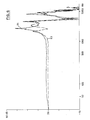
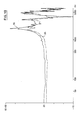
- a large peak at the resonance frequency is split into two smaller peaks occurring at lower and higher frequencies.
- the predetermined conditions of balance may be static or, more probably, dynamic at a selected low frequency.
- the counterweight is divided into a main body and an adaptor member connected together by the resilient connection.
- the adaptor member would be rigidly attached to the arm by the attachment means.
- the resilient connection may take any form, including springs, but is preferably a layer of elastomeric material operating in shear. Where the counterweight is divided, such an elastomeric layer would preferably be sandwiched between the counterweight and adaptor member.
- a preferred material for the layer is carbon filled ethylene propylene diamine (EPDM).
- a sandwiched shear layer is preferably planar other forms such as an arcuate layer could be employed.
- the head/arm assembly according to the invention which is illustrated in Figures 1 to 3 is designed to be located on and positioned by the rotary actuator illustrated in Figure 4 in order to access information storage tracks on the surfaces of a stack of disks (not shown) in a disk file.
- the head/arm assembly consists of two stacked cantilever arms 10, 11 of substantially planar form.
- the arms 10 each support at their tips a number of head suspension subassemblies 30.
- a counterweight 50 for balancing the arm at a predetermined low frequency about an axis of rotation 70.
- each arm 10 is a flat aluminium beam structure consisting of a thick parallel faced base portion 11 and a tapering extension framework 12, terminating in two head support blocks 13.
- Two aluminium sidebars 14 are located on respective limbs 15 of the arm 10 by features 17.
- the side bars 14 are bonded to the limbs by a layer of double sided adhesive tape (not shown) and fixed at one end by screws 18.
- the purpose of the sidebars is to damp out-of-plane resonances of the arms 10 in the manner explained in more detail in our European patent number 0060358-B1.
- each of the head support blocks 13 of the arms 10 Bolted to each of the head support blocks 13 of the arms 10 are the head suspension sub-assemblies 30, each comprising a head 31 on the end of a leaf spring flexure 32.
- Each block 13 of the upper arm 10 supports two such sub-assemblies 30.
- the lower block 13 has only one head suspension subassembly 30, on its upper surface.
- the lower surface which is not adjacent a disk, has a metal target plate 33 used in servowriting during manufacturing.
- Each head 31 is in the form of an air bearing slider on which a thin film transducing element (not shown) has been formed.
- head suspension subassemblies are described in more detail in our US Patent 4 167 765.
- External electrical connection of heads 31 is by means of wires 34 which lead to a tape cable (not shown) on the upper surface of the arm 10 and in turn to a conventional flexible cable (omitted for clarity) on the side of the arm stack.
- flexures 32 are inclined out of the plane of arms 10 to urge their respective heads 31 towards the surface of an information storage disk (not shown) which, in operation, rotates past the head 31.
- an information storage disk (not shown) which, in operation, rotates past the head 31.
- One such disk will pass between the arms 10 while another will pass over the top of the upper arm.
- each arm 10 After each arm 10 has been populated with heads and suspensions, the two arms are aligned and clamped together by means of a mandrel 40 passing through a large bore in each arm centred on axis 70. Clamping is effected by a draw bolt 41 which draws a clamp plate 42 towards the lower end of the mandrel until the plate engages the underside of base portion 11 of the lower arm 10.
- the counterweight 50 which will be described in more detail below, is bolted to the upper arm 10 by bolt 51.
- the head/arm assembly of Figures 1 to 3 is designed to be located on the rotary actuator 80 shown in Figure 4.
- the actuator is similar to that shown in our European patent number 0031876-B1 and includes a spindle extension table 81 for receiving the head/arm assembly.
- the table 81 is integral with an underlying spindle mounted for rotation in bearings about an axis coincident with axis 70.
- the table 81 is joined to the upper surface of a cup rotor 82 by means of reversed bosses 83.
- the rotor which comprises encapsulated pancake coil windings located within a flux gap in a magnetic circuit, is only permitted a very limited angle of rotation defined by crash stops 84. A portion 85 of the flux gap is visible between the outer edge of the rotor and its soft magnetic shroud 86.
- the head/arm assembly is located axially on the spindle extension table 81 by the engagement of two features 43 on the underside of the lower arm 10 with a boss 87 on the table 81. Circumferential location is provided by the engagement of a nib 44 on the arm with a post 88 on the table 81. When so located, the head/arm assembly and actuator table are bolted together through bores 45 in the stack to threaded bores 89 in the actuator table.
- the actuator 80 When assembled in this manner in a disk file the actuator 80 is servo controlled to position heads 31 over selected tracks on the disks. Servo patterns written on the disks are detected by heads 31 and modulated to provide position error feedback to the servo system. For maximum performance, the servo system must be designed with an appropriate gain/bandwidth characteristic. However, resonances in the mechanical system may necessitate a reduction in the bandwidth of the servo system to prevent instability and thus limit access time and track density.
- Functions 91 and 92 differ according to the degree of additional damping introduced.
- the counterweight 50 is divided into an auxiliary mass portion 52 and an adaptor plate 53.
- the mass 52 and plate 53 are joined by a layer 54 of carbon filled EPDM (ethylene propylene diamine) which provides the necessary resilient connection for the auxiliary mass 52. Shear damping by layer 54 also absorbs additional energy to reduce further the amplitude of the resonance.
- the layer 54 is moulded between the plane faces of mass 52 and plate 53 and cured in situ to bond to the faces. Because it has a low glass transition temperature, EPDM offers a more stable stiffness for the resilient connection over the working temperature range. Furthermore, such temperature changes as do occur do tend to result in the damping frequency tracking the rotor resonance frequency which also shifts with temperature.
- the entire counterweight 50 is bolted to the upper arm 10 by bolt 51 which is seated in the adaptor plate 53.
- a large hole 55 through the auxiliary mass 52 and damping layer 54 allows the bolt 51 to be inserted.
- FIG. 7 A modified form of counterweight is shown in Figures 7, 8 and 9. Apart from the counterweight 150, the head/arm assembly illustrated corresponds exactly to that shown in Figures 1, 2 and 3 and will not be described again.
- Counterweight 150 is also divided into auxiliary mass 152 and an adaptor plate 153 joined by a shear damping layer 154.
- the counterweight is bolted to the upper head arm by a bolt 151.
- the auxiliary mass 152 is differently shaped from the mass 52 in being part circular cylindrical and in having a projecting portion 155. This portion extends clear of the upper arm and of the damping layer 154, perpendicular to the plane of the arm.
Landscapes
- Moving Of Heads (AREA)
Priority Applications (3)
| Application Number | Priority Date | Filing Date | Title |
|---|---|---|---|
| DE8686303939T DE3680667D1 (de) | 1986-05-23 | 1986-05-23 | Kopf/arm-zusammenbau und rotierender zugangsmechanismus fuer einen plattenspeicher. |
| EP86303939A EP0246375B1 (fr) | 1986-05-23 | 1986-05-23 | Assemblage tête/bras et mécanisme d'accès rotatif pour mémoire à disques |
| JP9106987A JPS62281172A (ja) | 1986-05-23 | 1987-04-15 | デイスク・フアイルのためのア−ム組立体 |
Applications Claiming Priority (1)
| Application Number | Priority Date | Filing Date | Title |
|---|---|---|---|
| EP86303939A EP0246375B1 (fr) | 1986-05-23 | 1986-05-23 | Assemblage tête/bras et mécanisme d'accès rotatif pour mémoire à disques |
Publications (2)
| Publication Number | Publication Date |
|---|---|
| EP0246375A1 true EP0246375A1 (fr) | 1987-11-25 |
| EP0246375B1 EP0246375B1 (fr) | 1991-07-31 |
Family
ID=8196018
Family Applications (1)
| Application Number | Title | Priority Date | Filing Date |
|---|---|---|---|
| EP86303939A Expired - Lifetime EP0246375B1 (fr) | 1986-05-23 | 1986-05-23 | Assemblage tête/bras et mécanisme d'accès rotatif pour mémoire à disques |
Country Status (3)
| Country | Link |
|---|---|
| EP (1) | EP0246375B1 (fr) |
| JP (1) | JPS62281172A (fr) |
| DE (1) | DE3680667D1 (fr) |
Cited By (3)
| Publication number | Priority date | Publication date | Assignee | Title |
|---|---|---|---|---|
| EP0243466A4 (fr) * | 1985-10-16 | 1988-03-23 | Hewlett Packard Co | Appareil et procede d'amortissement des positionneurs de tetes pour des unites de disques. |
| US7352537B2 (en) | 2005-06-24 | 2008-04-01 | Hitachi Global Storage Technologies Netherlands B.V. | Tuned damper for disk drive actuator arm |
| CN115602203A (zh) * | 2021-07-12 | 2023-01-13 | 株式会社 东芝(Jp) | 盘装置 |
Citations (4)
| Publication number | Priority date | Publication date | Assignee | Title |
|---|---|---|---|---|
| FR2089595A5 (fr) * | 1970-05-25 | 1972-01-07 | Ibm | |
| GB2005379A (en) * | 1977-09-30 | 1979-04-19 | Ibm | Electromagnetic actuator and coil/carrier unit for such anactuator |
| EP0060358A1 (fr) * | 1981-03-18 | 1982-09-22 | International Business Machines Corporation | Dispositif de support d'une tête et montage de support d'une tête pour mémoires à disque |
| EP0121057A1 (fr) * | 1983-03-30 | 1984-10-10 | International Business Machines Corporation | Suspension d'un transducteur |
Family Cites Families (4)
| Publication number | Priority date | Publication date | Assignee | Title |
|---|---|---|---|---|
| JPS57103169A (en) * | 1980-12-16 | 1982-06-26 | Nec Corp | Positioning carriage of magnetic disk device |
| JPS58175167A (ja) * | 1982-04-08 | 1983-10-14 | Fujitsu Ltd | 磁気デイスク装置 |
| DE3673159D1 (de) * | 1985-10-16 | 1990-09-06 | Hewlett Packard Co | Vorrichtung und verfahren zur daempfung der koepfe von plattenantrieben. |
| JPS62110676A (ja) * | 1985-11-08 | 1987-05-21 | Nec Corp | 磁気デイスク装置の位置決めキヤリツジ |
-
1986
- 1986-05-23 DE DE8686303939T patent/DE3680667D1/de not_active Expired - Lifetime
- 1986-05-23 EP EP86303939A patent/EP0246375B1/fr not_active Expired - Lifetime
-
1987
- 1987-04-15 JP JP9106987A patent/JPS62281172A/ja active Pending
Patent Citations (4)
| Publication number | Priority date | Publication date | Assignee | Title |
|---|---|---|---|---|
| FR2089595A5 (fr) * | 1970-05-25 | 1972-01-07 | Ibm | |
| GB2005379A (en) * | 1977-09-30 | 1979-04-19 | Ibm | Electromagnetic actuator and coil/carrier unit for such anactuator |
| EP0060358A1 (fr) * | 1981-03-18 | 1982-09-22 | International Business Machines Corporation | Dispositif de support d'une tête et montage de support d'une tête pour mémoires à disque |
| EP0121057A1 (fr) * | 1983-03-30 | 1984-10-10 | International Business Machines Corporation | Suspension d'un transducteur |
Non-Patent Citations (3)
| Title |
|---|
| IBM TECHNICAL DISCLOSURE BULLETIN, vol. 25, no. 2, July 1982, pages 835,836, Armonk, New York, US; T.P. BREW et al.: "Assembly of head/arm stacks on rotary actuator" * |
| PATENTS ABSTRACTS OF JAPAN, vol. 9, no. 170 (P-373)[1893], 16th July 1985; & JP-A-60 47 272 (HITACHI SEISAKUSHO K.K.) 14-03-1985 * |
| PATENTS ABSTRACTS OF JAPAN, vol. 9, no. 297 (M-432)[2020], 25th November 1985; & JP-A-60 136 632 (HITACHI SEISAKUSHO K.K.) 20-07-1985 * |
Cited By (3)
| Publication number | Priority date | Publication date | Assignee | Title |
|---|---|---|---|---|
| EP0243466A4 (fr) * | 1985-10-16 | 1988-03-23 | Hewlett Packard Co | Appareil et procede d'amortissement des positionneurs de tetes pour des unites de disques. |
| US7352537B2 (en) | 2005-06-24 | 2008-04-01 | Hitachi Global Storage Technologies Netherlands B.V. | Tuned damper for disk drive actuator arm |
| CN115602203A (zh) * | 2021-07-12 | 2023-01-13 | 株式会社 东芝(Jp) | 盘装置 |
Also Published As
| Publication number | Publication date |
|---|---|
| JPS62281172A (ja) | 1987-12-07 |
| EP0246375B1 (fr) | 1991-07-31 |
| DE3680667D1 (de) | 1991-09-05 |
Similar Documents
| Publication | Publication Date | Title |
|---|---|---|
| EP0060358B1 (fr) | Dispositif de support d'une tête et montage de support d'une tête pour mémoires à disque | |
| US4812932A (en) | Vibration proof supporting structure for disk-type information memory unit | |
| US5459921A (en) | Method of making a disc drive actuator arm with arm compliance compensation | |
| EP0098008B1 (fr) | Montage de la plaque de base d'une mémoire à disque avec amortissement des vibrations | |
| US5491598A (en) | Rotary actuator vibration damper | |
| US6847595B2 (en) | Lens actuator | |
| US5124855A (en) | Disk file with isolation mount | |
| US5764441A (en) | Head actuator having reduced and controlled vibration characteristics for high speed disk drive systems | |
| US5914836A (en) | Cantilevered support for the magnetic circuit of a disc drive voice coil motor | |
| US6898042B2 (en) | Slider level microactuator with integrated fly control | |
| US20020141114A1 (en) | Damper for attenuating hard disk drive suspension vibration | |
| US6775106B1 (en) | E-block having improved resonance characteristics and improved fragility | |
| US5075808A (en) | Retaining clamp for a disc storage apparatus | |
| US6310749B1 (en) | Voice coil motor actuator vibration isolator | |
| US6064547A (en) | Damped disk separator | |
| US5023861A (en) | Single stage tracking actuator apparatus for optical beam information storage drive system | |
| US5136446A (en) | Apparatus for movably supporting and positioning a transducer | |
| US3838455A (en) | Head carriage assembly for magnetic disk storage apparatus | |
| US7016157B1 (en) | E-block having improved resonance characteristics and improved fragility | |
| EP0246375B1 (fr) | Assemblage tête/bras et mécanisme d'accès rotatif pour mémoire à disques | |
| Aruga et al. | High-speed orthogonal power effect actuator for recording at over 10000 TPI | |
| US4888656A (en) | Pivot mechanism for rotary disc drives | |
| US20020034053A1 (en) | Magnetic disk drive | |
| US5018035A (en) | Disc storage apparatus having an arcuate pivot assembly | |
| GB2127610A (en) | Magnetic disc transducer arm |
Legal Events
| Date | Code | Title | Description |
|---|---|---|---|
| PUAI | Public reference made under article 153(3) epc to a published international application that has entered the european phase |
Free format text: ORIGINAL CODE: 0009012 |
|
| AK | Designated contracting states |
Kind code of ref document: A1 Designated state(s): DE FR GB |
|
| 17P | Request for examination filed |
Effective date: 19880329 |
|
| 17Q | First examination report despatched |
Effective date: 19891211 |
|
| GRAA | (expected) grant |
Free format text: ORIGINAL CODE: 0009210 |
|
| AK | Designated contracting states |
Kind code of ref document: B1 Designated state(s): DE FR GB |
|
| REF | Corresponds to: |
Ref document number: 3680667 Country of ref document: DE Date of ref document: 19910905 |
|
| ET | Fr: translation filed | ||
| PLBE | No opposition filed within time limit |
Free format text: ORIGINAL CODE: 0009261 |
|
| STAA | Information on the status of an ep patent application or granted ep patent |
Free format text: STATUS: NO OPPOSITION FILED WITHIN TIME LIMIT |
|
| 26N | No opposition filed | ||
| PGFP | Annual fee paid to national office [announced via postgrant information from national office to epo] |
Ref country code: GB Payment date: 19930427 Year of fee payment: 8 Ref country code: FR Payment date: 19930427 Year of fee payment: 8 |
|
| PGFP | Annual fee paid to national office [announced via postgrant information from national office to epo] |
Ref country code: DE Payment date: 19930525 Year of fee payment: 8 |
|
| PG25 | Lapsed in a contracting state [announced via postgrant information from national office to epo] |
Ref country code: GB Effective date: 19940523 |
|
| GBPC | Gb: european patent ceased through non-payment of renewal fee |
Effective date: 19940523 |
|
| PG25 | Lapsed in a contracting state [announced via postgrant information from national office to epo] |
Ref country code: FR Effective date: 19950131 |
|
| PG25 | Lapsed in a contracting state [announced via postgrant information from national office to epo] |
Ref country code: DE Effective date: 19950201 |
|
| REG | Reference to a national code |
Ref country code: FR Ref legal event code: ST |