EP0246410A2 - Moteur à induction - Google Patents
Moteur à induction Download PDFInfo
- Publication number
- EP0246410A2 EP0246410A2 EP87103685A EP87103685A EP0246410A2 EP 0246410 A2 EP0246410 A2 EP 0246410A2 EP 87103685 A EP87103685 A EP 87103685A EP 87103685 A EP87103685 A EP 87103685A EP 0246410 A2 EP0246410 A2 EP 0246410A2
- Authority
- EP
- European Patent Office
- Prior art keywords
- rotor
- induction motor
- motor according
- rotary element
- stator
- Prior art date
- Legal status (The legal status is an assumption and is not a legal conclusion. Google has not performed a legal analysis and makes no representation as to the accuracy of the status listed.)
- Withdrawn
Links
Images


Classifications
-
- H—ELECTRICITY
- H02—GENERATION; CONVERSION OR DISTRIBUTION OF ELECTRIC POWER
- H02K—DYNAMO-ELECTRIC MACHINES
- H02K21/00—Synchronous motors having permanent magnets; Synchronous generators having permanent magnets
- H02K21/46—Motors having additional short-circuited winding for starting as an asynchronous motor
-
- H—ELECTRICITY
- H02—GENERATION; CONVERSION OR DISTRIBUTION OF ELECTRIC POWER
- H02K—DYNAMO-ELECTRIC MACHINES
- H02K7/00—Arrangements for handling mechanical energy structurally associated with dynamo-electric machines, e.g. structural association with mechanical driving motors or auxiliary dynamo-electric machines
- H02K7/10—Structural association with clutches, brakes, gears, pulleys or mechanical starters
- H02K7/11—Structural association with clutches, brakes, gears, pulleys or mechanical starters with dynamo-electric clutches
Definitions
- the invention relates to an induction motor which contains a stator with a stator winding and a rotor connected to a motor shaft and separated from the stator via an air gap.
- the power factor can be selected as desired in a wide setting range.
- the induction motors are electrical machines in which a stator with a stator winding and a rotor are provided which has a winding in which the rotor current is induced via the stator winding.
- the simplest design of the induction motors can be equipped with a squirrel-cage rotor (short-circuit rotor), the cage consisting of rods and rings (short-circuit rings) connected to the rods on the end face of the rotor.
- the efficiency of the electric motors can be defined by the ratio of the effective power that can be taken off the shaft to the power drawn from the network. In the case of induction motors, the latter depends on the voltage, the current and the phase angle. The effective power that can be removed from the shaft depends on many different factors. It is clear that the efficiency can be improved by reducing the power drawn from the network with the value of the effective power unchanged or changed to a limited extent.
- the reactive power depends on the supply voltage and the supply current as well as the power factor, the power factor being the cosine of the phase angle difference between the current and the voltage.
- the disadvantage of the known solution is that the improvement in the power factor is difficult to adjust, i.e. different power factors can occur with different motors of the same construction.
- the object of the invention is to improve the efficiency of the induction motors with simple means, ie to create an induction motor, the power factor of which is designed for an arbitrarily selected operating point with a predetermined value and with high accuracy can be.
- the invention is based on the knowledge that the increase and adjustability of the power factor can be achieved by using a supplementary rotor in the rotor if the rotor is made of ferromagnetic material and is supported in a free-running manner with respect to the rotor.
- a supplementary runner is e.g. can be seen from DE-A-30 45 820.
- a squirrel-cage rotor and an inner rotor provided with a winding are installed concentrically with one another on the motor shaft, the outer rotor and the stator being connected to an external voltage source. Different speeds of the rotors can be achieved in this way.
- the engine designed in this way is a special machine in which it is not possible to increase the power factor.
- an induction motor which contains a stator with a stator winding and a rotor separated from it via an air gap and connected to a motor shaft, the rotor being designed with a current-conducting element and a magnetically excited body and according to the invention in the air gap between the stator and the rotor arranged, freely supported against the rotor, prepared from permanent magnetic (pre-magnetized ferromagnetic) material is provided rotating element
- the rotor is arranged coaxially either above the current-conducting element (the cage or the winding) of the rotor or in an air gap between the current-conducting element and the magnetically excited body of the rotor.
- the induction motor can be constructed with an inner rotor, a middle rotor or an outer rotor. Accordingly, the rotating element can be mounted on the rotor either on its outer surface or on the body, further on the motor shaft and, if an external rotor is used, on the stator.
- the rotating element is advantageously at least as long as the part of the rotor lying below it. It is expedient to design the rotary element as a roller-shaped sleeve which, for example, consists of thin ferromagnetic strips and, thanks to the premagnetization, has the same number of poles as the stator winding.
- the ferromagnetic tapes premagnetized in the radial direction may be on the inner or outer surface of a magnetically non-excitable metallic, e.g. prepared from aluminum prepared roller.
- the base material of the bands can be iron or a rare metal magnet (for example samarium-cobalt or neodimium-based material).
- the rotating element supported on the stand is advantageously designed as a circular ring which also consists of ferromagnetic material which is premagnetized in the radial direction.
- the rotating element forms a disk which is mounted on the motor shaft, the ferromagnetic material of the disk being premagnetized in the axial direction.
- the induction motor if it contains a short-circuit rotor provided with a cage, it is advantageous to support the rotary element on a short-circuit ring, the short-circuit ring being firmly connected to the current-carrying element.
- the support is generally via needle bearings or plain bearings.
- asynchronous induction motor according to the invention is therefore invented
- a supplementary synchronous rotor is provided which, either directly supported on the motor shaft or movably supported on the rotor, forms a part which runs freely in synchronism with the magnetic rotating field of the motor and can contribute to excitation of the rotor of the induction motor.
- the amount of copper in the motor and the power required for excitation can be reduced and the reactive power drawn from the network is reduced. This reduces the energy consumption from the electrical network.
- the power factor can be assigned to a preselected operating point with the desired value.
- the solution according to the invention can simplify the absorption of the effective power from the network in relation to the absorption of the reactive power at the end points of the network; this reduces the reactive power consumption of the system fed by the network.
- the invention can be used both for single-phase and three-phase induction motors of any power (for example from 40 W to 1000 kW), and in particular for the motors used in households.
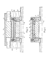
- a housing 1 or a holding plate is provided for fixing a stator 2 provided with stator windings 3.
- a rotor is installed coaxially to the stator 2, which rotor is provided with rotor windings 5 (FIGS. 1 and 5) or with a cage 15 (FIGS. 2 to 4) in a conventional manner.
- the rotor windings 5 or the cage 15 form the rotor together with a magnetically excited body 4 of known construction (e.g. laminated core), an air gap 13 being provided between the stator 2 and the rotor.
- the conventional motor structure is modified according to the invention in such a way that an additional rotary element 6 is provided between the stator 2 and the magnetically excited body 4, which can rotate freely with respect to the rotor which is firmly supported on the motor shaft 10.
- the rotor therefore consists of the body 4 and the rotor windings 5 or the cage 15, and is adapted to the rotary element 6, which is freely supported on the motor shaft 10 directly or on the body 4.
- the rotating element 6 is made of a permanent magnetic material and can wal be zen-shaped or annular.
- the rotary element 6 is supported concentrically to the rotor via bearings, in particular needle bearings 8, on the motor shaft 10 or the first part 4, in particular the rotor winding 5.
- a disk 7 serves to support the roller-shaped rotating element 6, and that is supported on the nail bearings 8.
- the latter are adapted snap rings 9, one or more clamping screws 11 being provided for fastening the rotary element 6 to the disk 7.
- slide bearings 18 FIG. 3
- the disc 7 is made of a light material, such as plastic or aluminum; it does not have to be made of a ferromagnetic material.
- the rotor of the induction motor is equipped with a cage 15 (FIGS. 2, 3 and 4), a short-circuit ring 16 being provided which is firmly connected to the body 4.
- the short-circuit ring 16 serves to support the nail bearings 8 and offers the possibility of simple installation of the rotary element 6.
- the use of a split rotor creates two air gaps in the interior of the induction motor.
- the rotating element 6 occupies part of the air gap 13 between the stator 2 and the rotor.
- the enlargement of the air gap 13 increases the magnetizing current of the induction motor, but this can be compensated for by the appropriate selection of the permanent magnetic material of the rotating element 6.
- an inner air gap 14 can be formed in the rotor, which is in or under the cage 15, but always above the body 4.
- the inner air gap 14 - which is not absolutely necessary - receives the rotary element 6, which is arranged in the all-round closed inner air gap 14 and is secured at a higher level against interference windings.
- the cage 15 is made of aluminum or other non-feromagnetic metal (FIG. 3 or 4) and in this embodiment is firmly connected to the respective disk 7 via the clamping screws 11.
- the discs 7 are firmly connected to the motor shaft 10 via tongue springs 12.
- the plain bearings 18 shown in FIG. 3 can be replaced by the nail bearings 8 according to FIG.
- the stator 2 has no slot and the stator winding 3 is embedded in synthetic resin; it forms an air gap winding.
- the rotating element 6 is constructed in the form of a flat disk arranged axially between the shaft-fixed body 4 of the rotor and the stator 2.
- the straight planes of rotation of the rotor and the rotating element 6 are parallel in this solution.
- the rotating element 6 can be supported both on the stator 2 (e.g. on a circular disc-shaped projection thereon), on the motor shaft 10 and - as can be seen in FIG. 5 - on the rotor in a free-running manner via the bearing 8.
- the bearings are loaded in accordance with the difference between the speed of the asynchronous motor and that of the synchronous motor. Therefore, the life of the bearings is long.
- the energy requirement is low because of the use of the rotating element 6 as a synchronous rotor part of the induction motor, which leads to a very small value of the load angle, regardless of whether the rotating element 6 is installed inside or outside the rotor.
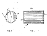
- the rotating element 6 can be roller-shaped (FIGS. 1 to 4), disk-shaped (FIG. 5) or circular.
- the ring-shaped configuration is similar to the roller-shaped or disc-shaped - depending on the arrangement of the magnetic material of the rotating element shown below.
- the rotating element 6 has a cylindrical shape, it serves as an envelope surrounding the rotor, which is closed on both sides with end walls 23 made of a light material such as plastic or aluminum.
- the end walls 23 are adapted to the bearings 8 or 18 (not shown in FIGS. 6 and 7) and are connected to a holding cylinder 22 suitably prepared as a hollow body made of aluminum or plastic.
- ferromagnetic tapes 21 are glued, which have been produced, for example, by powder metallurgical methods.
- the tapes 21 are advantageously pre-magnetized in the radial direction in a known manner so that the number of poles of the magnetic field is equal to the number of poles of the stator winding 3. If necessary, 21 air gaps can be prepared in the holding cylinder 22 between the bands.
- the holding cylinder 22 can independently form the rotary element 6 if it consists of a ferromagnetic material, the end walls 23 being formed, for example, from plastic.
- the rotating element 6 is a disk, as can be seen from FIG. 5, the strips 21 are glued on perpendicular to the motor shaft 10 and premagnetized in the axial direction.
- the disc can be made of non-ferromagnetic material (with glued ferromagnetic tapes) as well as a ferromagnetic material (without tapes).
- the roller-shaped rotating element 6 and also the disk-shaped or ring-shaped rotating element can be supported both on the motor shaft 10 and in the stator 2 or in the rotor, the adaptation, the installation, expediently depending on the motor design, being able to be determined.
- the rotary element 6 causes an increase in the air gap between the stator 2 and the rotor, which in itself results in a slight deterioration in the working parameters (the would increase the magnetizing current).
- This effect follows the fact that, due to its thickness, the rotating element requires an increase in the distance between the stator and the rotor.
- the thickness of the rotating element is generally about 3 ... 3.5 mm; it can be larger for higher engine outputs.
- the presence of the ferromagnetic rotary element 6 is associated with such advantages that the mentioned deterioration is completely compensated for, since the modern ferromagnetic materials can ensure a really high coercive force.
- the advantages of the synchronous motors and the induction motors are combined in such a way that the rotary element 6, as a supplementary rotor, provides magnetic energy, whereby the magnetization of the motor is facilitated and less power from the network is required to build up the main magnetic field (rotating field).
- the supply voltage is switched on (which is single-phase or three-phase)
- a circularly symmetrical or elliptical magnetic field is created in the stator winding, which rotates at synchronous speed.
- the rotor and the rotating element 6 are accelerated to the asynchronous speed, upon reaching which the rotating element 6 is further accelerated to the synchronous speed in a very fast-running process.
- the rotating element 6 causes excitation which is added to that of the main magnetic field of the motor.
- the magnetic excitation between the stand and the rotor can be significantly increased with the appropriate selection of the materials.
- the acceleration of the rotating element can be improved by the presence of a magnetically non-excitable metal in the ferromagnetic material as the holding cylinder 22, which ensures a cage effect.
- the power factor can be set according to the requirements. At loads lower than those following the power factor, the induction motor works capacitively as an overexcited synchronous motor, and when the load exceeds that corresponding to the selected operating point, the reactive current requirement is significantly lower than with the known induction motors.
- the rotary element according to the invention can be used in all induction motors.
- the motor power, the number of winding poles, the number of phases of the supply voltage, the arrangement of the rotor are practically not limited;
- the supplementary rotor can be used in the motor without further ado and then a significant improvement in the energetic properties (with a power factor of up to 0.95, i.e. with reduced consumption of reactive power) can be expected.
Landscapes
- Engineering & Computer Science (AREA)
- Power Engineering (AREA)
- Permanent Magnet Type Synchronous Machine (AREA)
- Iron Core Of Rotating Electric Machines (AREA)
- Permanent Field Magnets Of Synchronous Machinery (AREA)
- Induction Machinery (AREA)
Applications Claiming Priority (2)
| Application Number | Priority Date | Filing Date | Title |
|---|---|---|---|
| HU861670A HU195598B (en) | 1986-04-22 | 1986-04-22 | Auxiliary rotor of permanent magnet for asynchronous motors |
| HU167086 | 1986-04-22 |
Publications (2)
| Publication Number | Publication Date |
|---|---|
| EP0246410A2 true EP0246410A2 (fr) | 1987-11-25 |
| EP0246410A3 EP0246410A3 (fr) | 1988-08-24 |
Family
ID=10955601
Family Applications (1)
| Application Number | Title | Priority Date | Filing Date |
|---|---|---|---|
| EP87103685A Withdrawn EP0246410A3 (fr) | 1986-04-22 | 1987-03-13 | Moteur à induction |
Country Status (5)
| Country | Link |
|---|---|
| US (1) | US4745318A (fr) |
| EP (1) | EP0246410A3 (fr) |
| JP (1) | JPS6323545A (fr) |
| DE (1) | DE3632161A1 (fr) |
| HU (1) | HU195598B (fr) |
Cited By (7)
| Publication number | Priority date | Publication date | Assignee | Title |
|---|---|---|---|---|
| EP0274150A3 (en) * | 1986-12-06 | 1988-07-27 | Philips Patentverwaltung Gmbh | Single-phase synchronous motor with a bipolar permanent-magnet rotor and with an eddy current intermediate rotor |
| EP1416616A1 (fr) | 2002-10-26 | 2004-05-06 | LG Electronics Inc. | Moteur électrique |
| EP1521346A2 (fr) | 2003-09-30 | 2005-04-06 | Lg Electronics Inc. | bobinage et épanouissements polaires pour un stator |
| EP1455435A3 (fr) * | 2003-03-04 | 2005-05-04 | Lg Electronics Inc. | Moteur asynchrone monophasé comprenant une unité aux aimants permanents |
| EP1835601A3 (fr) * | 2006-03-17 | 2010-12-08 | LG Electronics Inc. | Moteur asynchrone hybride |
| KR20200026325A (ko) * | 2012-09-19 | 2020-03-10 | 구글 엘엘씨 | 현재 재생되는 텔레비젼 프로그램들과 연관된 인터넷-액세스가능 컨텐츠의 식별 및 제시 |
| US11006175B2 (en) | 2012-09-19 | 2021-05-11 | Google Llc | Systems and methods for operating a set top box |
Families Citing this family (18)
| Publication number | Priority date | Publication date | Assignee | Title |
|---|---|---|---|---|
| US4982128A (en) * | 1990-02-01 | 1991-01-01 | Mcdonald Maurice F | Double air gap alternator |
| JPH06170675A (ja) * | 1992-12-04 | 1994-06-21 | Toshiba Mach Co Ltd | 回転電機装置 |
| US5723928A (en) * | 1994-09-30 | 1998-03-03 | Toyoda Koki Kabushiki Kaisha | Induction motor and method of adjusting power factor of the same |
| US5864198A (en) * | 1994-10-14 | 1999-01-26 | Active Power, Inc. | Brushless generator |
| DE19548117A1 (de) * | 1994-12-23 | 1996-08-01 | Guenther Schmidt | Elektroantrieb mit stufenloser Lastmomentanpassung |
| US5828148A (en) * | 1997-03-20 | 1998-10-27 | Sundstrand Corporation | Method and apparatus for reducing windage losses in rotating equipment and electric motor/generator employing same |
| DE19953295B4 (de) * | 1999-11-05 | 2008-11-06 | Urenco Deutschland Gmbh | Verfahren zum Betreiben, Kontrollierten und Steuern von Hysteresemotoren |
| EP1219007A4 (fr) * | 1999-12-14 | 2003-01-15 | Delphi Tech Inc | Moteur sans balai a rotor a faible inertie |
| US6952068B2 (en) * | 2000-12-18 | 2005-10-04 | Otis Elevator Company | Fabricated components of transverse flux electric motors |
| KR100548278B1 (ko) * | 2003-09-17 | 2006-02-02 | 엘지전자 주식회사 | 하이브리드 인덕션 모터의 영구자석 및 그 착자방법 |
| JP2005139917A (ja) * | 2003-11-04 | 2005-06-02 | Aisin Seiki Co Ltd | 磁力駆動式ポンプ |
| KR100619751B1 (ko) * | 2004-10-23 | 2006-09-13 | 엘지전자 주식회사 | 셰이딩 코일형 단상 동기/유도 전동기 |
| KR100631551B1 (ko) * | 2004-12-21 | 2006-10-09 | 엘지전자 주식회사 | 이중자석 하이브리드 유도 전동기 |
| KR100653434B1 (ko) * | 2005-04-29 | 2006-12-01 | 영 춘 정 | 2상 무정류자 모터 |
| US8033007B2 (en) * | 2007-05-11 | 2011-10-11 | Sntech, Inc. | Method of making rotor of brushless motor |
| US8299661B2 (en) * | 2007-05-11 | 2012-10-30 | Sntech Inc. | Rotor of brushless motor |
| DE102008054475A1 (de) * | 2008-12-10 | 2010-06-17 | Zf Friedrichshafen Ag | Antriebsstrang für ein Kraftfahrzeug |
| JP2015195637A (ja) * | 2014-03-31 | 2015-11-05 | 日本電産サンキョー株式会社 | 排水弁駆動装置 |
Family Cites Families (10)
| Publication number | Priority date | Publication date | Assignee | Title |
|---|---|---|---|---|
| US2542659A (en) * | 1944-10-28 | 1951-02-20 | Glenn D Gillett | Drag-barrel motor |
| GB1107266A (en) * | 1963-10-04 | 1968-03-27 | Nat Res Dev | Dynamo electric machine |
| US3445699A (en) * | 1965-08-31 | 1969-05-20 | Reuland Electric Co | Multirotor induction motor |
| US3898490A (en) * | 1973-09-24 | 1975-08-05 | Westinghouse Electric Corp | Superconductive AC dynamoelectric machines having two rotors |
| GB1577265A (en) * | 1976-09-21 | 1980-10-22 | Sonceboz Sa | Electrical drive device |
| JPS6023584B2 (ja) * | 1977-12-14 | 1985-06-08 | 株式会社日立製作所 | 永久磁石式同期電動機 |
| DE2832165C2 (de) * | 1978-07-21 | 1982-04-22 | Naučno-issledovatel'skij i eksperimental'nyj institut avtomobil'nogo elektro-oborudovanija i avtopriborov, Moskva | Reluktanzgenerator |
| DE3045820A1 (de) * | 1980-12-02 | 1982-07-01 | Siemens AG, 1000 Berlin und 8000 München | Elektrische maschine |
| DE3232914C1 (de) * | 1982-09-04 | 1983-12-15 | Uranit GmbH, 5170 Jülich | Laeufer fuer einen Hysteresemotor |
| DE3420370A1 (de) * | 1984-01-02 | 1985-07-11 | Robert Bosch Gmbh, 7000 Stuttgart | Induktionsmotor |
-
1986
- 1986-04-22 HU HU861670A patent/HU195598B/hu unknown
- 1986-09-22 DE DE19863632161 patent/DE3632161A1/de not_active Ceased
-
1987
- 1987-03-13 EP EP87103685A patent/EP0246410A3/fr not_active Withdrawn
- 1987-04-21 JP JP62096344A patent/JPS6323545A/ja active Pending
- 1987-04-21 US US07/040,949 patent/US4745318A/en not_active Expired - Fee Related
Cited By (14)
| Publication number | Priority date | Publication date | Assignee | Title |
|---|---|---|---|---|
| EP0274150A3 (en) * | 1986-12-06 | 1988-07-27 | Philips Patentverwaltung Gmbh | Single-phase synchronous motor with a bipolar permanent-magnet rotor and with an eddy current intermediate rotor |
| EP1416616A1 (fr) | 2002-10-26 | 2004-05-06 | LG Electronics Inc. | Moteur électrique |
| US7239057B2 (en) | 2003-03-04 | 2007-07-03 | Lg Electronics Inc. | Single phase induction motor |
| CN100356665C (zh) * | 2003-03-04 | 2007-12-19 | Lg电子株式会社 | 单相感应电动机 |
| EP1455435A3 (fr) * | 2003-03-04 | 2005-05-04 | Lg Electronics Inc. | Moteur asynchrone monophasé comprenant une unité aux aimants permanents |
| EP1521346A3 (fr) * | 2003-09-30 | 2005-04-27 | Lg Electronics Inc. | bobinage et épanouissements polaires pour un stator |
| EP1521346A2 (fr) | 2003-09-30 | 2005-04-06 | Lg Electronics Inc. | bobinage et épanouissements polaires pour un stator |
| EP1835601A3 (fr) * | 2006-03-17 | 2010-12-08 | LG Electronics Inc. | Moteur asynchrone hybride |
| KR20200026325A (ko) * | 2012-09-19 | 2020-03-10 | 구글 엘엘씨 | 현재 재생되는 텔레비젼 프로그램들과 연관된 인터넷-액세스가능 컨텐츠의 식별 및 제시 |
| US11006175B2 (en) | 2012-09-19 | 2021-05-11 | Google Llc | Systems and methods for operating a set top box |
| US11140443B2 (en) | 2012-09-19 | 2021-10-05 | Google Llc | Identification and presentation of content associated with currently playing television programs |
| US11729459B2 (en) | 2012-09-19 | 2023-08-15 | Google Llc | Systems and methods for operating a set top box |
| US11917242B2 (en) | 2012-09-19 | 2024-02-27 | Google Llc | Identification and presentation of content associated with currently playing television programs |
| US12225263B2 (en) | 2012-09-19 | 2025-02-11 | Google Llc | Systems and methods for operating a set top box |
Also Published As
| Publication number | Publication date |
|---|---|
| US4745318A (en) | 1988-05-17 |
| JPS6323545A (ja) | 1988-01-30 |
| HU195598B (en) | 1988-05-30 |
| EP0246410A3 (fr) | 1988-08-24 |
| DE3632161A1 (de) | 1987-11-05 |
Similar Documents
| Publication | Publication Date | Title |
|---|---|---|
| EP0246410A2 (fr) | Moteur à induction | |
| DE2815217C2 (fr) | ||
| DE69717622T2 (de) | Selbstanlaufender bürstenloser elektromotor | |
| DE69126125T2 (de) | Ständer für dynamoelektrische maschinen | |
| DE69500829T2 (de) | Gleichstrommotor mit axialem Luftspalt | |
| EP0894360B1 (fr) | Machine electrique a courant continu | |
| DE69501066T3 (de) | Synchronmotor mit im Rotor eingebetteten Permanentmagneten | |
| DE1488353A1 (de) | Permanentmagneterregte elektrische Maschine | |
| EP0908630A1 (fr) | Petit appareil ventilateur spécialement utilisé comme ventilateur de circuit imprimé | |
| DE102019214623B4 (de) | Synchronmaschine, elektrische Antriebseinrichtung umfassend eine Synchronmaschine, sowie Ansteuerverfahren für eine Synchronmaschine | |
| DE2831518A1 (de) | Elektrische maschine | |
| DE102011111352A1 (de) | Elektromotor mit eisenloser Wicklung | |
| EP1459425A2 (fr) | Machine synchrone electrique a enroulement toroidal | |
| DE3122049A1 (de) | Kollektorloser gleichstromaussenlaeufermotor | |
| DE2062486A1 (de) | Permanenterregte elektrische Maschine | |
| DE6811162U (de) | Dynamoelektrische maschine mit reluktanzwirkung. | |
| DE102009010162A1 (de) | Elektromaschine für ein Wellenarray | |
| DE1160080B (de) | Elektromagnetisches System, insbesondere fuer einen Gleichstrommotor | |
| DE3844074C2 (fr) | ||
| DE102006057295A1 (de) | Magnetoelektrischer Generator | |
| EP0195741B1 (fr) | Machine électrique du type synchrone à excitation à aimant permanent | |
| DE3332659C2 (fr) | ||
| WO2021170272A1 (fr) | Moteur électrique | |
| DE3230283C2 (fr) | ||
| DE2126395A1 (de) | Elektrische Maschine |
Legal Events
| Date | Code | Title | Description |
|---|---|---|---|
| PUAI | Public reference made under article 153(3) epc to a published international application that has entered the european phase |
Free format text: ORIGINAL CODE: 0009012 |
|
| AK | Designated contracting states |
Kind code of ref document: A2 Designated state(s): AT BE CH DE ES FR GB GR IT LI LU NL SE |
|
| PUAL | Search report despatched |
Free format text: ORIGINAL CODE: 0009013 |
|
| AK | Designated contracting states |
Kind code of ref document: A3 Designated state(s): AT BE CH DE ES FR GB GR IT LI LU NL SE |
|
| STAA | Information on the status of an ep patent application or granted ep patent |
Free format text: STATUS: THE APPLICATION IS DEEMED TO BE WITHDRAWN |
|
| 18D | Application deemed to be withdrawn |
Effective date: 19890528 |
|
| RIN1 | Information on inventor provided before grant (corrected) |
Inventor name: IVANICS, LASZLO, DIPL.-ING. |