EP0247325A2 - Dispositif de filtration - Google Patents
Dispositif de filtration Download PDFInfo
- Publication number
- EP0247325A2 EP0247325A2 EP87104664A EP87104664A EP0247325A2 EP 0247325 A2 EP0247325 A2 EP 0247325A2 EP 87104664 A EP87104664 A EP 87104664A EP 87104664 A EP87104664 A EP 87104664A EP 0247325 A2 EP0247325 A2 EP 0247325A2
- Authority
- EP
- European Patent Office
- Prior art keywords
- filter
- pressure
- pump
- frame
- liquid
- Prior art date
- Legal status (The legal status is an assumption and is not a legal conclusion. Google has not performed a legal analysis and makes no representation as to the accuracy of the status listed.)
- Granted
Links
Images


Classifications
-
- B—PERFORMING OPERATIONS; TRANSPORTING
- B01—PHYSICAL OR CHEMICAL PROCESSES OR APPARATUS IN GENERAL
- B01D—SEPARATION
- B01D35/00—Filtering devices having features not specifically covered by groups B01D24/00 - B01D33/00, or for applications not specifically covered by groups B01D24/00 - B01D33/00; Auxiliary devices for filtration; Filter housing constructions
- B01D35/26—Filters with built-in pumps filters provided with a pump mounted in or on the casing
-
- B—PERFORMING OPERATIONS; TRANSPORTING
- B01—PHYSICAL OR CHEMICAL PROCESSES OR APPARATUS IN GENERAL
- B01D—SEPARATION
- B01D35/00—Filtering devices having features not specifically covered by groups B01D24/00 - B01D33/00, or for applications not specifically covered by groups B01D24/00 - B01D33/00; Auxiliary devices for filtration; Filter housing constructions
- B01D35/02—Filters adapted for location in special places, e.g. pipe-lines, pumps, stop-cocks
- B01D35/027—Filters adapted for location in special places, e.g. pipe-lines, pumps, stop-cocks rigidly mounted in or on tanks or reservoirs
-
- B—PERFORMING OPERATIONS; TRANSPORTING
- B01—PHYSICAL OR CHEMICAL PROCESSES OR APPARATUS IN GENERAL
- B01D—SEPARATION
- B01D35/00—Filtering devices having features not specifically covered by groups B01D24/00 - B01D33/00, or for applications not specifically covered by groups B01D24/00 - B01D33/00; Auxiliary devices for filtration; Filter housing constructions
- B01D35/02—Filters adapted for location in special places, e.g. pipe-lines, pumps, stop-cocks
- B01D35/027—Filters adapted for location in special places, e.g. pipe-lines, pumps, stop-cocks rigidly mounted in or on tanks or reservoirs
- B01D35/0273—Filtering elements with a horizontal or inclined rotation or symmetry axis submerged in tanks or reservoirs
-
- B—PERFORMING OPERATIONS; TRANSPORTING
- B01—PHYSICAL OR CHEMICAL PROCESSES OR APPARATUS IN GENERAL
- B01D—SEPARATION
- B01D35/00—Filtering devices having features not specifically covered by groups B01D24/00 - B01D33/00, or for applications not specifically covered by groups B01D24/00 - B01D33/00; Auxiliary devices for filtration; Filter housing constructions
- B01D35/30—Filter housing constructions
Definitions
- the present invention relates to a filter device which is arranged in the liquid to be filtered and releases the filtrate directly into this liquid.
- the present invention relates to an underwater filter device.
- Underwater filter devices which draw water to be cleaned through a filter by means of a pump and in which the cleaned water is then returned directly from the pressure side of the pump into the basin. These devices have the disadvantage that they are limited in terms of performance and that the filters are relatively cumbersome to replace, since the filters have to be uncoupled from the device on both the suction and the discharge side. This requires double sealing devices and possibly even double coupling devices.
- the delivery side of the filter is free, i.e. there is no significant length lead on the discharge side. Rather, the filtrate is released from the filter essentially directly in the container from which it was sucked in. If, in the embodiment of the invention with two pumps, the two discharge sides are connected to the same filter, this enables a flexible working method, in which one can work with both peak loads and continuous operation.
- the intake sides of the two filters can also be connected in parallel with an intake port.
- the arrangement of the individual elements with respect to the filter is such that, by loosening the connection between the filter and the rest of the device, it can fall freely out of the device and in this way can get into a filter receptacle.
- the filter will expediently hang vertically under the connecting device, so that the filter automatically frees itself from the device when the connection is released and can fall into a receptacle.
- a substantially cylindrical filter is particularly suitable, which is connected to the rest of the device on the end face.
- the with the container liquid in Contacting parts of the device made of inert, corrosion-resistant material, especially stainless steel or stainless steel.
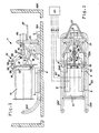
- the underwater filter device 1 is arranged on the bottom 101 of a container 100. Water to be cleaned is sucked in through the suction nozzle 3 arranged in the vicinity of the floor 101, which is connected by means of lines 4, 4 ⁇ to the suction side of a pump 5, 5 ⁇ .
- Two pumps 5 and 5 ⁇ are provided, which are connected in parallel in order to be able to switch over different operating states, namely continuous operation with the additional security, if one pump 5 or 5 ⁇ fails to the other pump 5 ⁇ or 5, and peak operation, in which both Pumps 5 and 5 ⁇ work simultaneously and in parallel.
- a connecting device 31 or an unlocking and locking device 31 is also fastened to the frame 21.
- three guide plates 33 are attached, which have a beveled run-up surface 35.
- the connecting device 31 has three hooks 37 rotatably mounted on the guide plates 33 at 34. By pivoting the hooks 37, the flanges 15 and 17 are either pressed firmly together and connected to one another, whereby an elastic seal (not shown) arranged between the flanges 15 and 17 comes into sealing engagement with the flanges 15 and 17, or the flanges 15 and 17 be released.
- the device 1 on the suspension bracket 27 is then raised by means of a hook (not shown) and moved over a filter receptacle. As a result of this lifting, the device tilts and the curved end sections 231 and 231 ⁇ hang down, as does the filter 11.
- two tabs 470, 470 ⁇ are attached to the frame tube element 21 shaped as an inverted V.
- these tabs 470, 470 ⁇ each have an opening 471, 471 ⁇ attached, which serves to receive the lifting element on the suspension cable with which the device can then be moved into the liquid container as described above.
- the advantage of attaching two fastening elements in this embodiment is that the movement of the device can thus be better controlled.
Landscapes
- Chemical & Material Sciences (AREA)
- Chemical Kinetics & Catalysis (AREA)
- Filtration Of Liquid (AREA)
- Farming Of Fish And Shellfish (AREA)
- Surgical Instruments (AREA)
- Separation By Low-Temperature Treatments (AREA)
- Centrifugal Separators (AREA)
- External Artificial Organs (AREA)
- Separation Using Semi-Permeable Membranes (AREA)
Priority Applications (1)
| Application Number | Priority Date | Filing Date | Title |
|---|---|---|---|
| AT87104664T ATE78711T1 (de) | 1986-05-27 | 1987-03-30 | Filtervorrichtung. |
Applications Claiming Priority (2)
| Application Number | Priority Date | Filing Date | Title |
|---|---|---|---|
| DE3617739A DE3617739C2 (de) | 1986-05-27 | 1986-05-27 | Filtervorrichtung, insbesondere Unterwasser-Filtervorrichtung und Filtrierverfahren |
| DE3617739 | 1986-05-27 |
Publications (3)
| Publication Number | Publication Date |
|---|---|
| EP0247325A2 true EP0247325A2 (fr) | 1987-12-02 |
| EP0247325A3 EP0247325A3 (en) | 1988-08-10 |
| EP0247325B1 EP0247325B1 (fr) | 1992-07-29 |
Family
ID=6301702
Family Applications (1)
| Application Number | Title | Priority Date | Filing Date |
|---|---|---|---|
| EP87104664A Expired - Lifetime EP0247325B1 (fr) | 1986-05-27 | 1987-03-30 | Dispositif de filtration |
Country Status (4)
| Country | Link |
|---|---|
| EP (1) | EP0247325B1 (fr) |
| AT (1) | ATE78711T1 (fr) |
| DE (2) | DE3617739C2 (fr) |
| ES (1) | ES2033251T3 (fr) |
Cited By (2)
| Publication number | Priority date | Publication date | Assignee | Title |
|---|---|---|---|---|
| DE4118432A1 (de) * | 1991-06-05 | 1992-12-10 | Pall Corp | Filteranordnung und verfahren zum austauschen von filterelementen in einer filteranordnung |
| CN102441299A (zh) * | 2010-10-05 | 2012-05-09 | 卡尔德·加布尔加德 | 可漂浮清洁组件 |
Families Citing this family (1)
| Publication number | Priority date | Publication date | Assignee | Title |
|---|---|---|---|---|
| DE19846591C2 (de) | 1998-10-09 | 2001-06-13 | Keld Gabelgaard | Verfahren zur Umspülung von Stabelementen und Verwendung des Verfahrens zur Reinigung von Brennelementen |
Family Cites Families (6)
| Publication number | Priority date | Publication date | Assignee | Title |
|---|---|---|---|---|
| DE284116C (fr) * | 1900-01-01 | |||
| DE257612C (fr) * | ||||
| US1813601A (en) * | 1929-07-29 | 1931-07-07 | Standard Oil Co | Filter opening means |
| DE1985012U (de) * | 1967-12-04 | 1968-05-09 | Alfred E Stejskal | Filter-pumpenanlage zum reinigen von fluessigkeitsbehaeltern, insbesondere badebecken. |
| AU425195B2 (en) * | 1969-03-14 | 1972-06-09 | Marvel Engineering Company | Air-operated filtering system |
| DE3320619A1 (de) * | 1983-02-08 | 1984-08-09 | Andreas 4040 Neuss Krüll | Filteranlage fuer schwimmbecken |
-
1986
- 1986-05-27 DE DE3617739A patent/DE3617739C2/de not_active Expired - Lifetime
-
1987
- 1987-03-30 EP EP87104664A patent/EP0247325B1/fr not_active Expired - Lifetime
- 1987-03-30 AT AT87104664T patent/ATE78711T1/de not_active IP Right Cessation
- 1987-03-30 DE DE8787104664T patent/DE3780706D1/de not_active Expired - Lifetime
- 1987-03-30 ES ES198787104664T patent/ES2033251T3/es not_active Expired - Lifetime
Cited By (3)
| Publication number | Priority date | Publication date | Assignee | Title |
|---|---|---|---|---|
| DE4118432A1 (de) * | 1991-06-05 | 1992-12-10 | Pall Corp | Filteranordnung und verfahren zum austauschen von filterelementen in einer filteranordnung |
| CN102441299A (zh) * | 2010-10-05 | 2012-05-09 | 卡尔德·加布尔加德 | 可漂浮清洁组件 |
| CN102441299B (zh) * | 2010-10-05 | 2015-10-21 | 卡尔德·加布尔加德 | 可漂浮清洁组件 |
Also Published As
| Publication number | Publication date |
|---|---|
| DE3617739C2 (de) | 1996-05-30 |
| DE3780706D1 (de) | 1992-09-03 |
| EP0247325A3 (en) | 1988-08-10 |
| EP0247325B1 (fr) | 1992-07-29 |
| ATE78711T1 (de) | 1992-08-15 |
| DE3617739A1 (de) | 1987-12-03 |
| ES2033251T3 (es) | 1993-03-16 |
Similar Documents
| Publication | Publication Date | Title |
|---|---|---|
| EP0989255B1 (fr) | Appareil de nettoyage pour piscine | |
| EP1237640B1 (fr) | Dispositif filtrant a retrolavage | |
| EP0538191A1 (fr) | Cafetière | |
| DE3441891A1 (de) | Verfahren und vorrichtung zum absaugen von sekretfluessigkeit aus einer wunde | |
| AT407955B (de) | Anordnung zum umfüllen von blut | |
| DE3902943C2 (fr) | ||
| DE69422477T3 (de) | Melkmaschine | |
| DE60014451T2 (de) | Filtervorrichtung für flüssige substanzen geeignet für den einsatz in fleisch-einspritzmaschinen | |
| DE69019614T2 (de) | Filter zur automatischen Reinigung von Flüssigkeitskreisläufen. | |
| DE102009012444A1 (de) | Vorrichtung und Verfahren zum Filtern einer Flüssigkeit | |
| DE3134861C2 (de) | Magnetfilter | |
| EP0629749B1 (fr) | Appareil pour nettoyer les égouts | |
| DE3042619C2 (de) | Vorrichtung zur Kanal- und Grubenreinigung | |
| EP0247325B1 (fr) | Dispositif de filtration | |
| DE102004004756A1 (de) | Filtervorrichtung | |
| DE3937378C2 (fr) | ||
| DE1436302B2 (de) | Anschwemmfilter | |
| EP0245715A2 (fr) | Dispositif de traitement de liquides contenant des impuretés, résidus et/ou des produits de vieillissement | |
| DE1298081B (de) | Austragsvorrichtung fuer ein Nutschfilter | |
| DE3808407A1 (de) | Handbetaetigtes saugreinigungsgeraet fuer schwimmbecken | |
| EP3851415A1 (fr) | Dispositif de séparation et procédé de séparation des solides d'un mélange solide-liquide | |
| DE2831821C3 (de) | Filter für ein Aquarium | |
| DE2124083C3 (de) | Vorrichtung zur Reinigung eines Mop | |
| DE1621604B1 (de) | Vorrichtung zum Reinigen, insbesondere von verschmu tzten Werkstücken | |
| DE3300596C1 (de) | Siebanlage fuer die mechanische Reinigung von in einem offenen Gerinne fliessendem Wasser |
Legal Events
| Date | Code | Title | Description |
|---|---|---|---|
| PUAI | Public reference made under article 153(3) epc to a published international application that has entered the european phase |
Free format text: ORIGINAL CODE: 0009012 |
|
| AK | Designated contracting states |
Kind code of ref document: A2 Designated state(s): AT BE CH DE ES FR GB IT LI NL SE |
|
| PUAL | Search report despatched |
Free format text: ORIGINAL CODE: 0009013 |
|
| AK | Designated contracting states |
Kind code of ref document: A3 Designated state(s): AT BE CH DE ES FR GB IT LI NL SE |
|
| 17P | Request for examination filed |
Effective date: 19890123 |
|
| 17Q | First examination report despatched |
Effective date: 19901012 |
|
| GRAA | (expected) grant |
Free format text: ORIGINAL CODE: 0009210 |
|
| AK | Designated contracting states |
Kind code of ref document: B1 Designated state(s): AT BE CH DE ES FR GB IT LI NL SE |
|
| REF | Corresponds to: |
Ref document number: 78711 Country of ref document: AT Date of ref document: 19920815 Kind code of ref document: T |
|
| ITF | It: translation for a ep patent filed | ||
| REF | Corresponds to: |
Ref document number: 3780706 Country of ref document: DE Date of ref document: 19920903 |
|
| GBT | Gb: translation of ep patent filed (gb section 77(6)(a)/1977) | ||
| ET | Fr: translation filed | ||
| REG | Reference to a national code |
Ref country code: ES Ref legal event code: FG2A Ref document number: 2033251 Country of ref document: ES Kind code of ref document: T3 |
|
| PLBE | No opposition filed within time limit |
Free format text: ORIGINAL CODE: 0009261 |
|
| STAA | Information on the status of an ep patent application or granted ep patent |
Free format text: STATUS: NO OPPOSITION FILED WITHIN TIME LIMIT |
|
| 26N | No opposition filed | ||
| EAL | Se: european patent in force in sweden |
Ref document number: 87104664.5 |
|
| REG | Reference to a national code |
Ref country code: GB Ref legal event code: IF02 |
|
| PGFP | Annual fee paid to national office [announced via postgrant information from national office to epo] |
Ref country code: NL Payment date: 20030317 Year of fee payment: 17 |
|
| PGFP | Annual fee paid to national office [announced via postgrant information from national office to epo] |
Ref country code: AT Payment date: 20030321 Year of fee payment: 17 |
|
| PG25 | Lapsed in a contracting state [announced via postgrant information from national office to epo] |
Ref country code: AT Free format text: LAPSE BECAUSE OF NON-PAYMENT OF DUE FEES Effective date: 20040330 |
|
| PG25 | Lapsed in a contracting state [announced via postgrant information from national office to epo] |
Ref country code: NL Free format text: LAPSE BECAUSE OF NON-PAYMENT OF DUE FEES Effective date: 20041001 |
|
| NLV4 | Nl: lapsed or anulled due to non-payment of the annual fee |
Effective date: 20041001 |
|
| PG25 | Lapsed in a contracting state [announced via postgrant information from national office to epo] |
Ref country code: IT Free format text: LAPSE BECAUSE OF NON-PAYMENT OF DUE FEES;WARNING: LAPSES OF ITALIAN PATENTS WITH EFFECTIVE DATE BEFORE 2007 MAY HAVE OCCURRED AT ANY TIME BEFORE 2007. THE CORRECT EFFECTIVE DATE MAY BE DIFFERENT FROM THE ONE RECORDED. Effective date: 20050330 |
|
| PGFP | Annual fee paid to national office [announced via postgrant information from national office to epo] |
Ref country code: FR Payment date: 20060308 Year of fee payment: 20 |
|
| PGFP | Annual fee paid to national office [announced via postgrant information from national office to epo] |
Ref country code: CH Payment date: 20060329 Year of fee payment: 20 Ref country code: GB Payment date: 20060329 Year of fee payment: 20 |
|
| PGFP | Annual fee paid to national office [announced via postgrant information from national office to epo] |
Ref country code: DE Payment date: 20060406 Year of fee payment: 20 |
|
| PGFP | Annual fee paid to national office [announced via postgrant information from national office to epo] |
Ref country code: ES Payment date: 20060425 Year of fee payment: 20 |
|
| PGFP | Annual fee paid to national office [announced via postgrant information from national office to epo] |
Ref country code: BE Payment date: 20060509 Year of fee payment: 20 |
|
| PG25 | Lapsed in a contracting state [announced via postgrant information from national office to epo] |
Ref country code: GB Free format text: LAPSE BECAUSE OF EXPIRATION OF PROTECTION Effective date: 20070329 |
|
| PG25 | Lapsed in a contracting state [announced via postgrant information from national office to epo] |
Ref country code: ES Free format text: LAPSE BECAUSE OF EXPIRATION OF PROTECTION Effective date: 20070331 |
|
| REG | Reference to a national code |
Ref country code: CH Ref legal event code: PL |
|
| EUG | Se: european patent has lapsed | ||
| REG | Reference to a national code |
Ref country code: ES Ref legal event code: FD2A Effective date: 20070331 |
|
| BE20 | Be: patent expired |
Owner name: *GABELGAARD KELD Effective date: 20070330 |
|
| PGFP | Annual fee paid to national office [announced via postgrant information from national office to epo] |
Ref country code: SE Payment date: 20060306 Year of fee payment: 20 |