EP0247325B1 - Dispositif de filtration - Google Patents
Dispositif de filtration Download PDFInfo
- Publication number
- EP0247325B1 EP0247325B1 EP87104664A EP87104664A EP0247325B1 EP 0247325 B1 EP0247325 B1 EP 0247325B1 EP 87104664 A EP87104664 A EP 87104664A EP 87104664 A EP87104664 A EP 87104664A EP 0247325 B1 EP0247325 B1 EP 0247325B1
- Authority
- EP
- European Patent Office
- Prior art keywords
- filter
- pressure
- pump
- frame
- liquid
- Prior art date
- Legal status (The legal status is an assumption and is not a legal conclusion. Google has not performed a legal analysis and makes no representation as to the accuracy of the status listed.)
- Expired - Lifetime
Links
- 238000001914 filtration Methods 0.000 title claims abstract description 6
- 239000007788 liquid Substances 0.000 claims description 15
- 238000000034 method Methods 0.000 claims description 11
- 238000004140 cleaning Methods 0.000 claims description 4
- 230000008878 coupling Effects 0.000 claims description 4
- 238000010168 coupling process Methods 0.000 claims description 4
- 238000005859 coupling reaction Methods 0.000 claims description 4
- 239000000706 filtrate Substances 0.000 claims description 4
- 238000007599 discharging Methods 0.000 claims 1
- XLYOFNOQVPJJNP-UHFFFAOYSA-N water Substances O XLYOFNOQVPJJNP-UHFFFAOYSA-N 0.000 description 7
- 229910001220 stainless steel Inorganic materials 0.000 description 3
- 239000010935 stainless steel Substances 0.000 description 3
- 239000000725 suspension Substances 0.000 description 3
- 238000007789 sealing Methods 0.000 description 2
- 230000009182 swimming Effects 0.000 description 2
- 238000005260 corrosion Methods 0.000 description 1
- 230000007797 corrosion Effects 0.000 description 1
- 239000000463 material Substances 0.000 description 1
- 230000032258 transport Effects 0.000 description 1
Images
Classifications
-
- B—PERFORMING OPERATIONS; TRANSPORTING
- B01—PHYSICAL OR CHEMICAL PROCESSES OR APPARATUS IN GENERAL
- B01D—SEPARATION
- B01D35/00—Filtering devices having features not specifically covered by groups B01D24/00 - B01D33/00, or for applications not specifically covered by groups B01D24/00 - B01D33/00; Auxiliary devices for filtration; Filter housing constructions
- B01D35/26—Filters with built-in pumps filters provided with a pump mounted in or on the casing
-
- B—PERFORMING OPERATIONS; TRANSPORTING
- B01—PHYSICAL OR CHEMICAL PROCESSES OR APPARATUS IN GENERAL
- B01D—SEPARATION
- B01D35/00—Filtering devices having features not specifically covered by groups B01D24/00 - B01D33/00, or for applications not specifically covered by groups B01D24/00 - B01D33/00; Auxiliary devices for filtration; Filter housing constructions
- B01D35/02—Filters adapted for location in special places, e.g. pipe-lines, pumps, stop-cocks
- B01D35/027—Filters adapted for location in special places, e.g. pipe-lines, pumps, stop-cocks rigidly mounted in or on tanks or reservoirs
-
- B—PERFORMING OPERATIONS; TRANSPORTING
- B01—PHYSICAL OR CHEMICAL PROCESSES OR APPARATUS IN GENERAL
- B01D—SEPARATION
- B01D35/00—Filtering devices having features not specifically covered by groups B01D24/00 - B01D33/00, or for applications not specifically covered by groups B01D24/00 - B01D33/00; Auxiliary devices for filtration; Filter housing constructions
- B01D35/02—Filters adapted for location in special places, e.g. pipe-lines, pumps, stop-cocks
- B01D35/027—Filters adapted for location in special places, e.g. pipe-lines, pumps, stop-cocks rigidly mounted in or on tanks or reservoirs
- B01D35/0273—Filtering elements with a horizontal or inclined rotation or symmetry axis submerged in tanks or reservoirs
-
- B—PERFORMING OPERATIONS; TRANSPORTING
- B01—PHYSICAL OR CHEMICAL PROCESSES OR APPARATUS IN GENERAL
- B01D—SEPARATION
- B01D35/00—Filtering devices having features not specifically covered by groups B01D24/00 - B01D33/00, or for applications not specifically covered by groups B01D24/00 - B01D33/00; Auxiliary devices for filtration; Filter housing constructions
- B01D35/30—Filter housing constructions
Definitions
- the present invention relates to a filter device which is arranged in the liquid to be filtered and releases the filtrate directly into this liquid.
- the present invention relates to an underwater filter device.
- Underwater filter devices which draw water to be cleaned through a filter by means of a pump and in which the cleaned water is then returned directly from the pressure side of the pump into the basin. These devices have the disadvantage that they are limited in terms of performance and that the filters are relatively cumbersome to replace, since the filters have to be uncoupled from the device on both the suction and the discharge side. This requires double sealing devices and possibly even double coupling devices.
- the German patent application DE-OS 33 20 619 describes a filter system for swimming pools, which is arranged overall in the swimming pool.
- the filter system consists of coarse and fine filters and a pump as well as a return pipe that transports back, whereby the pump is arranged below the coarse and fine filters in or on the filter pipe and is only detachably connected to the filter and the return pipe.
- the Australian patent specification AU-PS 425 195 describes an air-operated filter system with a filter element which is connected via a line to the pressure side of an air motor pump.
- the known filter system has no detachable connection between the filter inlet and the pump pressure side.
- the delivery side of the filter is free, i.e. there is no significant length lead on the discharge side. Rather, the filtrate is released from the filter essentially directly in the container from which it was sucked in. If, in the embodiment of the invention with two pumps, the two discharge sides are connected to the same filter, this enables a flexible working method, in which one can work with both peak loads and continuous operation.
- the intake sides of the two filters can also be connected in parallel with an intake port.
- the arrangement of the individual elements with respect to the filter is such that, by loosening the connection between the filter and the rest of the device, it can fall freely out of the device and in this way can get into a filter receptacle.
- the filter will expediently hang vertically under the connecting device, so that the filter automatically frees itself from the device when the connection is released and can fall into a receptacle.
- a substantially cylindrical filter is particularly suitable, which is connected to the rest of the device on the end face.
- the with the container liquid in Contacting parts of the device made of inert, corrosion-resistant material, especially stainless steel or stainless steel.
- the device is constructed in such a way that simply loosening the connection between the filter unit and the pump allows the former to fall out of the device freely and unhindered. There is then no need to operate any other mechanical device such.
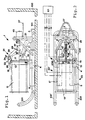
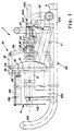
- the underwater filter device 1 is arranged on the bottom 101 of a container 100. Water to be cleaned is sucked in through the suction nozzle 3 arranged in the vicinity of the floor 101, which is connected to the suction side of a pump 5, 5 'by means of lines 4, 4'. Two pumps 5 and 5 'are provided, which are connected in parallel in order to be able to switch over to different operating states, namely continuous operation with the additional security, in the event of failure of one pump 5 or 5' to the other pump 5 'or 5, and peak operation, in which both pumps 5 and 5 'work simultaneously and in parallel.
- the pump 5 or 5 ' gives the sucked-in, contaminated water on the pressure side via connecting lines 7, 7' 7 '' and an inlet chamber 9 into the interior of a hollow cylindrical one Filter 11.
- the filtered water directly reaches the water of the container 100 again from the outside of the filter 11 arranged in the contaminated water of the container 100.
- the filter 11 is connected to an extension 13 to which a flange 15 is attached.
- a counter flange 17 is attached to a dome-like distributor element 19 which surrounds the inlet chamber 9.
- the distributor element 19 is fastened to a tubular frame 21 made of stainless steel elements.
- This frame 21 has two tubular sections 23, 23 'shaped like sled runners, each of which consists of a support section 230, 230' and a curved end section 231, 231 '.
- a suspension bracket 27 is fastened to the frame 21, on which the underwater filter device 1 can be lifted and moved.
- a connecting device 31 or an unlocking and locking device 31 is also fastened to the frame 21.
- three guide plates 33 are attached, which have a beveled run-up surface 35.
- the connecting device 31 has three hooks 37 rotatably mounted on the guide plates 33 at 34. By pivoting the hooks 37, the flanges 15 and 17 are either pressed firmly together and connected to one another, whereby an elastic seal (not shown) arranged between the flanges 15 and 17 comes into sealing engagement with the flanges 15 and 17, or the flanges 15 and 17 be released.
- the respective free end of the rotatably mounted hook 37 is connected to a central sleeve 41 via a respective guide rod 39. Only one of the three guide rods 39, which are all rotatably connected to the sleeve 41 at 49, is shown in the drawing.
- the sleeve 41 is by means of an internal thread along the threaded rod 43 on which the Sleeve 41 is screwed, movable.
- the threaded rod 43 is fixed to the axis or shaft of a motor 45.
- the free end of the threaded rod 43 is mounted in a bearing 47 which is connected to the dome-shaped distributor element 19.
- a pressure sensor 51 which generates a signal corresponding to the pressure in the filter 11, is arranged in the distribution chamber or on the pressure side of the pumps 5 and 5 '. If this signal represents a pressure that exceeds a limit value, then the pumps 5 and 5 'are switched off by the control device 61, to which the pressure sensor is operatively connected.
- the device 1 on the suspension bracket 27 is then raised by means of a hook (not shown) and moved over a filter receptacle. As a result of this lifting, the device tilts and the curved end sections 231 and 231 'hang down, as does the filter 11.
- the motor 45 is now actuated by the control device 61, so that the unit consisting of filter 11, extension 13 and flange 15 is released from the device by pivoting the hook 37 and falls off the device 1 and falls into the filter receptacle. From there, the unit can either be eliminated or further processed, e.g. B. be cleaned.
- the device 1 is now placed with flange 17 on a clean, not yet clogged filter unit. The precise alignment of the flanges 15 and 17 is facilitated and automated by the run-on surfaces 35 of the plates 33.
- the new filter unit is then swiveled by the hook 37 coupled.
- the device 1 is then lowered again onto the bottom 101 of the container 100.
- the cleaning process can now begin again.
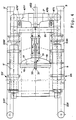
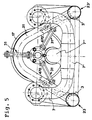
- FIGS. 3 to 5 in the three views, the same reference numerals have been largely used as in the embodiment according to FIGS. 1 and 2.
- the motor 45 is omitted from the illustration of this embodiment. This motor can be plugged onto the plug-in device 450, the locking taking place via a simple snap coupling with the slots 451 and the motor driving the shaft 452.
- the filter 11 is shown in FIG. 3 with additional details.
- a plurality of filter elements 110 are arranged on the flange plate 15 by means of a bayonet-type fastening. These filter elements 110 are pressed against the flange plate 15 by a pressure plate 112 and held in this position. The pressure plate 112 is pulled against the flange plate 5 by four pressure rods 114 (only one shown in FIG. 3).
- the pumps 5 and 5 ' are arranged somewhat higher and the two suction ports 3 are connected to the suction side of the pump via the line 230 and the connecting line 234 leading upwards.
- two tabs 470, 470 ' are fastened to the frame tube element 21 shaped as an inverted V.
- these tabs 470, 470 'each have an opening 471, 471' is attached, which serves to receive the lifting element on the suspension cable with which the device can then be moved into the liquid container as described above.
- the advantage of attaching two fastening elements in this embodiment is that the movement of the device can thus be better controlled.
Landscapes
- Chemical & Material Sciences (AREA)
- Chemical Kinetics & Catalysis (AREA)
- Filtration Of Liquid (AREA)
- Farming Of Fish And Shellfish (AREA)
- Surgical Instruments (AREA)
- Separation By Low-Temperature Treatments (AREA)
- Centrifugal Separators (AREA)
- External Artificial Organs (AREA)
- Separation Using Semi-Permeable Membranes (AREA)
Claims (14)
- Dispositif de filtration disposé dans un fluide à filtrer et présentanta) un châssis (21);b) au moins une pompe (5, respectivement 5') reliée au châssis (21); etc) un dispositif d'aspiration (3) relié au côté d'aspiration de la pompe (5, respectivement 5');
caractérisé pard) au moins un filtre (11) avec un côté admission, dans lequel le côté admission est relié au côté refoulement de la pompe;e) un côté évacuation du filtre (11), libre, par lequel le produit filtré repasse essentiellement directement du filtre (11) dans le fluide à filtrer;f) un raccordement détachable (31; 37) entre l'admission du filtre et le côté refoulement de la pompe, par lequel le filtre (11) peut être désaccouplé du dispositif (1); etg) un dispositif de commande (39, 41, 43) automatique, fixé directement ou indirectement sur le châssis (21) pour l'actionnement du raccordement amovible (31; 37). - Dispositif de filtration selon la revendication 1, caractérisé en ce que le filtre (11) est disposé de façon à ce qu'il puisse se détacher librement du dispositif (1) au moins dans une disposition de l'espace du dispositif (1), après déconnexion du raccordement (31; 37) et sans actionner d'autres moyens.
- Dispositif selon l'une des revendications précédentes, caractérisé en ce que deux pompes (5 et 5') sont reliées directement ou indirectement au châssis (21).
- Dispositif selon la revendication 3, caractérisé en ce que les deux pompes (5, 5') sont raccordées du côté refoulement, au même filtre (11).
- Dispositif selon l'une des revendications précédentes, caractérisé en ce que le dispositif de commande présente un moteur (45) fixé au châssis (21), qui actionne le raccordement amovible (31; 37).
- Dispositif selon la revendication 5, caractérisé en ce que le dispositif de commande présente un premier engrenage d'un axe (43) et d'un manchon (41) vissé sur l'axe (43), ledit engrenage transformant le mouvement rotatif du moteur (45) en un mouvement linéaire du manchon (41), et un deuxième engrenage avec un système de tiges (39) qui est relié au manchon (41) du premier engrenage, et qui permet le désaccouplement, respectivement la fermeture du raccordement (31; 37).
- Dispositif selon l'une des revendications précédentes caractérisé en ce que le dispositif de raccordement présente un dispositif de serrage mécanique (37) qui maintient une flasque (15) du filtre et une flasque d'évacuation (17) connectée au côté refoulement de la pompe (5, respectivement 5'), et qui est peut être déconnecté automatiquement.
- Dispositif selon l'une des revendications précédentes, caractérisé en ce que le filtre (11) est conçu comme un filtre cylindrique creux qui est fermé sur un côté et dans lequel l'autre côté est relié avec le côté refoulement de la pompe (5, respectivement 5') de sorte que le liquide est refoulé de la pompe sur le côté interne du cylindre creux.
- Dispositif selon l'une des revendications précédentes, caractérisé parun élément de fixation (27) pour un vérin, qui est disposé par rapport au dispositif de telle sorte que par soulèvement du dispositif (1) du fond d'un réservoir dans lequel est placé le dispositif, ce dispositif tourne d'un angle prédéterminé, en particulier d'environ 90°, ce qui permet au dispositif d'atteindre celle des positions dans l'espace dans laquelle le filtre (11) se détache librement du dispositif lors de la déconnexion du raccordement.
- Dispositif selon l'une des revendications précédentes, caractérisé par un capteur de pression (51) produisant un signal correspondant à la pression de refoulement sur le côté admission du filtre.
- Dispositif selon la revendication 10, caractérisé par un organe de manoeuvre (61) comprenant une ouverture qui est reliée en opération au capteur de pression (51) de façon à ce que l'organe de manoeuvre déconnecte la pompe (5, respectivement 5') lorsque le signal du capteur de pression (51) indique le dépassement d'une valeur limite de pression.
- Procédé de nettoyage continu d'un fluide dans un réservoir au moyen d'un dispositif de filtre placé dans un réservoir, caractérisé par les différentes opérations suivantes :a) compression d'un fluide par un filtre (11) qui est disposé dans un châssis (21) dans le réservoir de fluide (100);b) passage d'un produit filtré du filtre (11) directement à nouveau dans le réservoir de fluide (100);c) déplacement du châssis (21) avec le filtre (11) contaminé par l'intermédiaire d'un dispositif d'admission du filtre;d) désaccouplement du filtre (11) contaminé du châssis (21) et transfert du filtre (11) dans le dispositif d'admission du filtre.
- Procédé selon la revendication 12, caractérisé par les opérations ultérieures suivantes :e) solidarisation d'un filtre neuf sur le châssis;f) déplacement du châssis (21) en un point du réservoir de fluide (100) pour le nettoyage ultérieur du fluide;g) répétition des opérations de nettoyage et de changement de filtre a) à g).
- Procédé selon l'une des revendications précédentes, caractérisé
en ce que la pression sur le côté admission du filtre est automatiquement décelé et en ce qu'un signal correspondant à cette pression est généré,
en ce que ce signal est donné par un organe de manoeuvre,
en ce que l'organe de manoeuvre délivre un signal qui déconnecte alors la pompe, respectivement les pompes lorsque le signal de la pression représente une pression qui dépasse une valeur limite de pression prédéterminée.
Priority Applications (1)
| Application Number | Priority Date | Filing Date | Title |
|---|---|---|---|
| AT87104664T ATE78711T1 (de) | 1986-05-27 | 1987-03-30 | Filtervorrichtung. |
Applications Claiming Priority (2)
| Application Number | Priority Date | Filing Date | Title |
|---|---|---|---|
| DE3617739A DE3617739C2 (de) | 1986-05-27 | 1986-05-27 | Filtervorrichtung, insbesondere Unterwasser-Filtervorrichtung und Filtrierverfahren |
| DE3617739 | 1986-05-27 |
Publications (3)
| Publication Number | Publication Date |
|---|---|
| EP0247325A2 EP0247325A2 (fr) | 1987-12-02 |
| EP0247325A3 EP0247325A3 (en) | 1988-08-10 |
| EP0247325B1 true EP0247325B1 (fr) | 1992-07-29 |
Family
ID=6301702
Family Applications (1)
| Application Number | Title | Priority Date | Filing Date |
|---|---|---|---|
| EP87104664A Expired - Lifetime EP0247325B1 (fr) | 1986-05-27 | 1987-03-30 | Dispositif de filtration |
Country Status (4)
| Country | Link |
|---|---|
| EP (1) | EP0247325B1 (fr) |
| AT (1) | ATE78711T1 (fr) |
| DE (2) | DE3617739C2 (fr) |
| ES (1) | ES2033251T3 (fr) |
Cited By (1)
| Publication number | Priority date | Publication date | Assignee | Title |
|---|---|---|---|---|
| EP2438974A1 (fr) | 2010-10-05 | 2012-04-11 | Keld Gabelgaard | Agencement de nettoyage flottant |
Families Citing this family (2)
| Publication number | Priority date | Publication date | Assignee | Title |
|---|---|---|---|---|
| DE4118432A1 (de) * | 1991-06-05 | 1992-12-10 | Pall Corp | Filteranordnung und verfahren zum austauschen von filterelementen in einer filteranordnung |
| DE19846591C2 (de) | 1998-10-09 | 2001-06-13 | Keld Gabelgaard | Verfahren zur Umspülung von Stabelementen und Verwendung des Verfahrens zur Reinigung von Brennelementen |
Family Cites Families (6)
| Publication number | Priority date | Publication date | Assignee | Title |
|---|---|---|---|---|
| DE284116C (fr) * | 1900-01-01 | |||
| DE257612C (fr) * | ||||
| US1813601A (en) * | 1929-07-29 | 1931-07-07 | Standard Oil Co | Filter opening means |
| DE1985012U (de) * | 1967-12-04 | 1968-05-09 | Alfred E Stejskal | Filter-pumpenanlage zum reinigen von fluessigkeitsbehaeltern, insbesondere badebecken. |
| AU425195B2 (en) * | 1969-03-14 | 1972-06-09 | Marvel Engineering Company | Air-operated filtering system |
| DE3320619A1 (de) * | 1983-02-08 | 1984-08-09 | Andreas 4040 Neuss Krüll | Filteranlage fuer schwimmbecken |
-
1986
- 1986-05-27 DE DE3617739A patent/DE3617739C2/de not_active Expired - Lifetime
-
1987
- 1987-03-30 EP EP87104664A patent/EP0247325B1/fr not_active Expired - Lifetime
- 1987-03-30 AT AT87104664T patent/ATE78711T1/de not_active IP Right Cessation
- 1987-03-30 DE DE8787104664T patent/DE3780706D1/de not_active Expired - Lifetime
- 1987-03-30 ES ES198787104664T patent/ES2033251T3/es not_active Expired - Lifetime
Cited By (1)
| Publication number | Priority date | Publication date | Assignee | Title |
|---|---|---|---|---|
| EP2438974A1 (fr) | 2010-10-05 | 2012-04-11 | Keld Gabelgaard | Agencement de nettoyage flottant |
Also Published As
| Publication number | Publication date |
|---|---|
| DE3617739C2 (de) | 1996-05-30 |
| DE3780706D1 (de) | 1992-09-03 |
| EP0247325A2 (fr) | 1987-12-02 |
| EP0247325A3 (en) | 1988-08-10 |
| ATE78711T1 (de) | 1992-08-15 |
| DE3617739A1 (de) | 1987-12-03 |
| ES2033251T3 (es) | 1993-03-16 |
Similar Documents
| Publication | Publication Date | Title |
|---|---|---|
| EP0989255B1 (fr) | Appareil de nettoyage pour piscine | |
| EP1237640B1 (fr) | Dispositif filtrant a retrolavage | |
| DE60201111T2 (de) | Rohrverbindung mit Sicherheitsverschluss für externe Filter von Aquarien | |
| DE3540783A1 (de) | Fahrbare nassreinigungsmaschine | |
| EP0380809B1 (fr) | Appareil pour introduire et retirer des liquides, en particulier de cavités du corps humain | |
| DE60014451T2 (de) | Filtervorrichtung für flüssige substanzen geeignet für den einsatz in fleisch-einspritzmaschinen | |
| EP0629749B1 (fr) | Appareil pour nettoyer les égouts | |
| EP0247325B1 (fr) | Dispositif de filtration | |
| DE3042619C2 (de) | Vorrichtung zur Kanal- und Grubenreinigung | |
| DE9301281U1 (de) | Vorrichtung zum Reinigen von Arbeitsgeräten von Malerbetrieben | |
| DE3937378C2 (fr) | ||
| DE19633057C1 (de) | Vorrichtung zum Reinigen von Wannen, die bei Betriebsbedingungen Flüssigkeit enthalten | |
| DE19943282C2 (de) | Verfahren zum Entfernen von Klärschschlamm aus einer Abwasserteichanlage | |
| EP1210483A2 (fr) | Suceur de vase | |
| DE3433572A1 (de) | Schlammsaugewagen | |
| DE2363751C3 (de) | Verfahren und Vorrichtung zum Betreiben eines Schwimmbeckens | |
| EP0265385B1 (fr) | Appareil pour le nettoyage d'un filtre ou d'une grille dans une installation d'épuration d'eau | |
| EP0280648B1 (fr) | Dispositif de nettoyage pour réservoirs d'épuration des eaux usées | |
| EP0218034A1 (fr) | Purification de plaques filtrantes | |
| EP0252996A1 (fr) | Dispositif pour le filtrage d'un liquide | |
| DE3808407A1 (de) | Handbetaetigtes saugreinigungsgeraet fuer schwimmbecken | |
| EP3851415A1 (fr) | Dispositif de séparation et procédé de séparation des solides d'un mélange solide-liquide | |
| DE9115948U1 (de) | Waschanlage für den Gummituchzylinder einer Offsetdruckmaschine | |
| DE3300596C1 (de) | Siebanlage fuer die mechanische Reinigung von in einem offenen Gerinne fliessendem Wasser | |
| DE2124083C3 (de) | Vorrichtung zur Reinigung eines Mop |
Legal Events
| Date | Code | Title | Description |
|---|---|---|---|
| PUAI | Public reference made under article 153(3) epc to a published international application that has entered the european phase |
Free format text: ORIGINAL CODE: 0009012 |
|
| AK | Designated contracting states |
Kind code of ref document: A2 Designated state(s): AT BE CH DE ES FR GB IT LI NL SE |
|
| PUAL | Search report despatched |
Free format text: ORIGINAL CODE: 0009013 |
|
| AK | Designated contracting states |
Kind code of ref document: A3 Designated state(s): AT BE CH DE ES FR GB IT LI NL SE |
|
| 17P | Request for examination filed |
Effective date: 19890123 |
|
| 17Q | First examination report despatched |
Effective date: 19901012 |
|
| GRAA | (expected) grant |
Free format text: ORIGINAL CODE: 0009210 |
|
| AK | Designated contracting states |
Kind code of ref document: B1 Designated state(s): AT BE CH DE ES FR GB IT LI NL SE |
|
| REF | Corresponds to: |
Ref document number: 78711 Country of ref document: AT Date of ref document: 19920815 Kind code of ref document: T |
|
| ITF | It: translation for a ep patent filed | ||
| REF | Corresponds to: |
Ref document number: 3780706 Country of ref document: DE Date of ref document: 19920903 |
|
| GBT | Gb: translation of ep patent filed (gb section 77(6)(a)/1977) | ||
| ET | Fr: translation filed | ||
| REG | Reference to a national code |
Ref country code: ES Ref legal event code: FG2A Ref document number: 2033251 Country of ref document: ES Kind code of ref document: T3 |
|
| PLBE | No opposition filed within time limit |
Free format text: ORIGINAL CODE: 0009261 |
|
| STAA | Information on the status of an ep patent application or granted ep patent |
Free format text: STATUS: NO OPPOSITION FILED WITHIN TIME LIMIT |
|
| 26N | No opposition filed | ||
| EAL | Se: european patent in force in sweden |
Ref document number: 87104664.5 |
|
| REG | Reference to a national code |
Ref country code: GB Ref legal event code: IF02 |
|
| PGFP | Annual fee paid to national office [announced via postgrant information from national office to epo] |
Ref country code: NL Payment date: 20030317 Year of fee payment: 17 |
|
| PGFP | Annual fee paid to national office [announced via postgrant information from national office to epo] |
Ref country code: AT Payment date: 20030321 Year of fee payment: 17 |
|
| PG25 | Lapsed in a contracting state [announced via postgrant information from national office to epo] |
Ref country code: AT Free format text: LAPSE BECAUSE OF NON-PAYMENT OF DUE FEES Effective date: 20040330 |
|
| PG25 | Lapsed in a contracting state [announced via postgrant information from national office to epo] |
Ref country code: NL Free format text: LAPSE BECAUSE OF NON-PAYMENT OF DUE FEES Effective date: 20041001 |
|
| NLV4 | Nl: lapsed or anulled due to non-payment of the annual fee |
Effective date: 20041001 |
|
| PG25 | Lapsed in a contracting state [announced via postgrant information from national office to epo] |
Ref country code: IT Free format text: LAPSE BECAUSE OF NON-PAYMENT OF DUE FEES;WARNING: LAPSES OF ITALIAN PATENTS WITH EFFECTIVE DATE BEFORE 2007 MAY HAVE OCCURRED AT ANY TIME BEFORE 2007. THE CORRECT EFFECTIVE DATE MAY BE DIFFERENT FROM THE ONE RECORDED. Effective date: 20050330 |
|
| PGFP | Annual fee paid to national office [announced via postgrant information from national office to epo] |
Ref country code: FR Payment date: 20060308 Year of fee payment: 20 |
|
| PGFP | Annual fee paid to national office [announced via postgrant information from national office to epo] |
Ref country code: CH Payment date: 20060329 Year of fee payment: 20 Ref country code: GB Payment date: 20060329 Year of fee payment: 20 |
|
| PGFP | Annual fee paid to national office [announced via postgrant information from national office to epo] |
Ref country code: DE Payment date: 20060406 Year of fee payment: 20 |
|
| PGFP | Annual fee paid to national office [announced via postgrant information from national office to epo] |
Ref country code: ES Payment date: 20060425 Year of fee payment: 20 |
|
| PGFP | Annual fee paid to national office [announced via postgrant information from national office to epo] |
Ref country code: BE Payment date: 20060509 Year of fee payment: 20 |
|
| PG25 | Lapsed in a contracting state [announced via postgrant information from national office to epo] |
Ref country code: GB Free format text: LAPSE BECAUSE OF EXPIRATION OF PROTECTION Effective date: 20070329 |
|
| PG25 | Lapsed in a contracting state [announced via postgrant information from national office to epo] |
Ref country code: ES Free format text: LAPSE BECAUSE OF EXPIRATION OF PROTECTION Effective date: 20070331 |
|
| REG | Reference to a national code |
Ref country code: CH Ref legal event code: PL |
|
| EUG | Se: european patent has lapsed | ||
| REG | Reference to a national code |
Ref country code: ES Ref legal event code: FD2A Effective date: 20070331 |
|
| BE20 | Be: patent expired |
Owner name: *GABELGAARD KELD Effective date: 20070330 |
|
| PGFP | Annual fee paid to national office [announced via postgrant information from national office to epo] |
Ref country code: SE Payment date: 20060306 Year of fee payment: 20 |