EP0247341A2 - Selbstverriegelnde Kupplungsvorrichtung - Google Patents
Selbstverriegelnde Kupplungsvorrichtung Download PDFInfo
- Publication number
- EP0247341A2 EP0247341A2 EP87105248A EP87105248A EP0247341A2 EP 0247341 A2 EP0247341 A2 EP 0247341A2 EP 87105248 A EP87105248 A EP 87105248A EP 87105248 A EP87105248 A EP 87105248A EP 0247341 A2 EP0247341 A2 EP 0247341A2
- Authority
- EP
- European Patent Office
- Prior art keywords
- lock nut
- receptacle
- nut
- teeth
- face
- Prior art date
- Legal status (The legal status is an assumption and is not a legal conclusion. Google has not performed a legal analysis and makes no representation as to the accuracy of the status listed.)
- Withdrawn
Links
- 230000008878 coupling Effects 0.000 title claims abstract description 26
- 238000010168 coupling process Methods 0.000 title claims abstract description 26
- 238000005859 coupling reaction Methods 0.000 title claims abstract description 26
- 230000014759 maintenance of location Effects 0.000 claims description 5
- 230000036316 preload Effects 0.000 abstract description 6
- 230000000717 retained effect Effects 0.000 abstract 1
- 230000001154 acute effect Effects 0.000 description 1
- 230000000295 complement effect Effects 0.000 description 1
- 150000001875 compounds Chemical class 0.000 description 1
- 230000006835 compression Effects 0.000 description 1
- 238000007906 compression Methods 0.000 description 1
- 239000004020 conductor Substances 0.000 description 1
- 230000003247 decreasing effect Effects 0.000 description 1
- 230000037431 insertion Effects 0.000 description 1
- 238000003780 insertion Methods 0.000 description 1
- 230000013011 mating Effects 0.000 description 1
- 239000002184 metal Substances 0.000 description 1
Images
Classifications
-
- H—ELECTRICITY
- H01—ELECTRIC ELEMENTS
- H01R—ELECTRICALLY-CONDUCTIVE CONNECTIONS; STRUCTURAL ASSOCIATIONS OF A PLURALITY OF MUTUALLY-INSULATED ELECTRICAL CONNECTING ELEMENTS; COUPLING DEVICES; CURRENT COLLECTORS
- H01R13/00—Details of coupling devices of the kinds covered by groups H01R12/70 or H01R24/00 - H01R33/00
- H01R13/62—Means for facilitating engagement or disengagement of coupling parts or for holding them in engagement
- H01R13/622—Screw-ring or screw-casing
Definitions
- This invention relates to an electrical connector assembly having a self-locking coupling arrangement.
- An electrical connector assembly typically comprises a plug and a threaded receptacle each carrying an electrical contact for mating, the plug being receivable within the receptacle whereby to mate therewith and establish electrical connection between the contacts, a threaded coupling nut rotatably carried on the plug which upon rotation engages the receptacle thread to move the plug and receptacle axially toward or away from one another depending on the direction of rotation, and an arrangement for resisting unwanted uncoupling rotation of the coupling nut once the assembly is mated.
- a self-locking coupling arrangement is characterized by a first and second cylindrical shell each having on its forward axial end face a contiguous set of teeth, the first shell being carried by the plug and defining a coupling nut which engages the receptacle to draw the shells axially together whereby the teeth are brought into engagement and the second shell being mounted for axial sliding movement relative to the receptacle and defining a lock nut, and means including a coil spring carried by the receptacle for resisting rearward movement of the lock nut.
- the assembly is either self-locking or rotation resisting.
- a detent cavity in the lock nut receives a pin extending radially from the receptacle and permits a user to change the axial position of the lock nut relative to the receptacle, such a change serving to increase/decrease the spring pre-load acting to bias the lock nut forwardly or when the shells are self-locked to manually, axially, retract the lock nut whereby to release the meshed teeth from engagement and allow uncoupling rotation of the coupling nut.
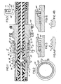
- FIGURE 1 shows a connector assembly including a plug section 10 mated to a receptacle section 22.
- the plug section comprises a generally cylindrical shell 12 having a forward end portion 14.
- a dielectric insert 16 having an axial passage 18 therethrough is mounted in the shell.
- a pin-type contact 20 is mounted in the passage.
- the receptacle section comprises a generally cylindrical shell 24 having a forward end portion 26 provided with external thread 28 and a medial portion provided with a radial shoulder 30, the shoulder defining an abutment surface facing axially forward.
- a dielectric insert 32 having an axial passage 34 therethrough is mounted in the shell.
- a socket-type contact 36 is mounted in the passage.
- a generally cylindrical coupling nut 40 is rotatably captivated on the plug shell by a retainer ring 38, the nut including on an interior wall thereof internal thread 44 adapted to engage with the external thread on the receptacle shell. Engagement of the thread 28,44 and rotation of the coupling nut 40 in one direction axially draws the plug shell 12 into the forward end portion of the receptacle shell 24 whereby the shells are mated and the contacts 20,36 are electrically interconnected. Rotation of the nut in the other direction uncouples the connector sections.
- the coupling nut has a cylindrical forward end portion 42 extending forwardly of the plug forward end face and terminating in an end face provided with a contiguous 360° plurality of forwardly facing teeth 46.
- a lock nut 50 is captivated on the receptacle shell for slidable axial movement relative thereto, an annular space being formed between the inner surface 51 of the lock nut and the outer surface 11 of the receptacle shell.
- the lock nut is generally cylindrical and includes a forward end portion 52 and a rearward end portion 56, the forward end portion 52 terminating in an end face provided with a contiguous 360° plurality of forwardly facing teeth 48 to engage the teeth 46 on the coupling nut 40 and the rearward end portion 56 being mounted to the receptacle shell.
- the forward end portion 52 includes an interior shoulder 54 which faces axially rearward and defines an abutment surface.
- the end faces of the lock nut 50 and coupling nut 40 are generally disposed in a plane perpendicular to the axis of rotation.
- each connector section Mounting a cooperating nut on each connector section allows the outside diameter of each nut to be substantially the same thereby reducing the size of the overall interconnection.
- a pair of axial coil springs 58 to resist axial rearward movement of the lock nut are enclosed in the annular space formed between the receptacle shell and the lock nut.
- Each spring has, respectively, one and the other end thereof abutting the interior shoulder 54 on the lock nut and the forwardly facing radial shoulder 30 on the receptacle shell.
- the springs are in compression and provided with a pre-load so that the resistance of the lock nut to rearward forces as would be applied by the teeth meshing may be either increased or decreased.
- a single coil spring could be disposed in the annular space such that its coils are completely encircling the outer surface of the receptacle shell.
- the lock nut 50 is constrained for axial movement relative to the receptacle.
- the rearward end portion 56 of the lock nut terminates in an end face 57 facing axially rearward and includes an L-shaped detent cavity 60, the foot 62 of the "L" opening onto the rear end face and the cavity including one or more axially extending detents 64.
- a key pin 66 extending radially from the receptacle shell is received in one of the detents 64 and constrains the shell to axial motion.
- FIGURE 3 shows the retention arrangement for the lock nut relative to the receptacle wherein the key pin 66 is received in a detent 64.
- the detents define axial grooves each being of different length and thereby allowing the lock nut position to be changed and thus the pre-load in the coil springs to be changed.
- the springs 58 would be positioned on the receptacle shell 24, and the rearward end portion 56 of the lock nut 50 coaxially inserted over the forward end portion of the receptacle.
- FIGURES 4A and 4B show contiguous V-shaped teeth which define the end faces 46,48 which mesh with one and the other, respectively, being self-locking and rotation resisting.
- Each self-locking tooth in FIGURE 4A has two engagement surfaces "A,B” with surface “A” and surface “B”, respectively, being generally 90° and acutely angled to the plane including its end face.
- the acutely angled surfaces "A” would serve as cams and drive the lock nut axially rearward to allow rotation but the other surfaces "B” would stop rotation.
- the user would grasp the lock nut 50 and pull it axially away from the coupling nut 40 whereby the two sets of teeth 46,48 are disengaged and the coupling nut may be rotated to disengage the thread.
- the teeth have two acutely-angled surfaces "A" with each serving as a cam thereby resisting rotation in both directions so long as the teeth 46,48 are interengaged.
- Rotation resistance can be changed by increasing the acute angle towards the 90° condition.
- FIGURE 5 shows a lock nut retention wherein a flange 68 extends radially outward from the receptacle shell, and the lock nut has a rearward end portion 70 thereof deformed radially inward to seat behind the flange, thereby "non-removably” retaining the lock nut and the springs to the receptacle shell.
- FIGURE 6 shows a lock nut retention wherein a flange 68 extends radially outward from the receptacle shell, the rearward end portion of the lock nut is provided with an annular groove, and a snap ring 72 is received in the groove, thereby "removably” retaining the lock nut and the springs to the receptacle shell.
Landscapes
- Details Of Connecting Devices For Male And Female Coupling (AREA)
- Dowels (AREA)
Applications Claiming Priority (2)
| Application Number | Priority Date | Filing Date | Title |
|---|---|---|---|
| US06/868,980 US4648671A (en) | 1986-05-29 | 1986-05-29 | Self locking coupling device |
| US868980 | 1986-05-29 |
Publications (2)
| Publication Number | Publication Date |
|---|---|
| EP0247341A2 true EP0247341A2 (de) | 1987-12-02 |
| EP0247341A3 EP0247341A3 (de) | 1989-01-18 |
Family
ID=25352698
Family Applications (1)
| Application Number | Title | Priority Date | Filing Date |
|---|---|---|---|
| EP87105248A Withdrawn EP0247341A3 (de) | 1986-05-29 | 1987-04-09 | Selbstverriegelnde Kupplungsvorrichtung |
Country Status (2)
| Country | Link |
|---|---|
| US (1) | US4648671A (de) |
| EP (1) | EP0247341A3 (de) |
Cited By (2)
| Publication number | Priority date | Publication date | Assignee | Title |
|---|---|---|---|---|
| WO1989006871A1 (en) * | 1988-01-20 | 1989-07-27 | Hughes Aircraft Company | Anti-backlash automatic locking connector coupling mechanism |
| GB2518157A (en) * | 2013-09-11 | 2015-03-18 | Mini Cam Ltd | A Connector |
Families Citing this family (10)
| Publication number | Priority date | Publication date | Assignee | Title |
|---|---|---|---|---|
| US4808123A (en) * | 1987-02-04 | 1989-02-28 | Diverse Termination Products, Inc. | Self-locking strain-relief end bell for electrical connector assembly |
| GB2292268B (en) * | 1994-08-13 | 1998-09-16 | B D Kendle Engineering Ltd | Electric line quick release connectors |
| GB2299460B (en) * | 1995-03-31 | 1998-12-30 | Ultra Electronics Ltd | Locking coupling |
| AUPQ889500A0 (en) * | 2000-07-20 | 2000-08-10 | Lock It Well Pty Ltd | Electrical connector device |
| AU2002224584B2 (en) * | 2000-07-20 | 2004-08-26 | Pia Australia Pty Ltd | Electrical connector device |
| CN101667693B (zh) * | 2009-10-02 | 2011-08-31 | 中航光电科技股份有限公司 | 连接器及其螺栓锁紧装置 |
| US9477049B2 (en) * | 2013-12-20 | 2016-10-25 | Senko Advanced Components, Inc. | Lockable connectors and connection assemblies |
| US9528646B2 (en) | 2014-05-02 | 2016-12-27 | Itt Manufacturing Enterprises, Llc | Locking and ratcheting connector |
| DE202018102532U1 (de) * | 2018-05-07 | 2018-05-22 | Neutrik Ag | Steckverbinderteil |
| CA3172487C (en) * | 2020-03-20 | 2023-06-20 | Patrice DEGUIRE | Set of electromechanical connectors having male and female structural members |
Family Cites Families (21)
| Publication number | Priority date | Publication date | Assignee | Title |
|---|---|---|---|---|
| US2784385A (en) * | 1954-02-02 | 1957-03-05 | Harlan M Ennis | Safety electric coupling |
| US2828978A (en) * | 1954-03-25 | 1958-04-01 | Paul D Wurzburger | Locking ring structure for pipe couplings |
| US2728895A (en) * | 1954-10-04 | 1955-12-27 | Whitney Blake Co | Self-locking coupling device |
| US2890434A (en) * | 1955-10-21 | 1959-06-09 | Anatoly B Ray | Electrical disconnect safety lock |
| US2829358A (en) * | 1956-06-15 | 1958-04-01 | Testori Giglio | Connectors with coupling lock |
| US3069187A (en) * | 1959-06-12 | 1962-12-18 | Parker Hannifin Corp | Coupling for tubes |
| US3517371A (en) * | 1968-03-04 | 1970-06-23 | Itt | Coupling locking device |
| GB1270423A (en) * | 1968-10-18 | 1972-04-12 | Stavrop Otdel Vni I Pk I Elekt | Plug and socket connector |
| US3608933A (en) * | 1969-08-22 | 1971-09-28 | Bowen Tools Inc | Lock ring assembly for locking threaded shouldered joints |
| US3673547A (en) * | 1970-05-22 | 1972-06-27 | Amp Inc | Connector for coaxial cable |
| DE2136500C3 (de) * | 1971-07-21 | 1979-10-18 | Siemens Ag, 1000 Berlin , 8000 Muenchen | HF-Koaxialsteckvorrichtung |
| US3936124A (en) * | 1974-11-01 | 1976-02-03 | Tuttle John D | Waterproof connector |
| US4030798A (en) * | 1975-04-11 | 1977-06-21 | Akzona Incorporated | Electrical connector with means for maintaining a connected condition |
| DE2546942C3 (de) * | 1975-10-20 | 1980-08-21 | Spinner-Gmbh Elektrotechnische Fabrik, 8000 Muenchen | HF-Koaxialstecker mit einer Überwurfmutter und Verfahren zur unverlierbaren Befestigung derselben |
| US4066314A (en) * | 1976-06-28 | 1978-01-03 | Williams Robert A | Electrical connector backshell accessory indexing body |
| DE2719730A1 (de) * | 1977-05-03 | 1978-11-09 | Akzona Inc | Verbindungsstueck fuer elektrische leitungen |
| GB1581476A (en) * | 1977-05-09 | 1980-12-17 | Bunker Ramo | Quick-release electrical connectors |
| DE2840728C2 (de) * | 1978-09-19 | 1980-09-04 | Georg Dipl.-Ing. Dr.-Ing. 8152 Feldkirchen-Westerham Spinner | HF-Koaxialsteckverbindung |
| US4506942A (en) * | 1982-12-02 | 1985-03-26 | Allied Corporation | Anti-decoupling mechanism for electrical connector |
| US4500154A (en) * | 1983-03-30 | 1985-02-19 | Allied Corporation | Electrical connector assembly having an anti-decoupling device |
| US4550966A (en) * | 1984-01-24 | 1985-11-05 | J & R Manufacturing, Inc. | Electrical cable connectors |
-
1986
- 1986-05-29 US US06/868,980 patent/US4648671A/en not_active Expired - Fee Related
-
1987
- 1987-04-09 EP EP87105248A patent/EP0247341A3/de not_active Withdrawn
Cited By (3)
| Publication number | Priority date | Publication date | Assignee | Title |
|---|---|---|---|---|
| WO1989006871A1 (en) * | 1988-01-20 | 1989-07-27 | Hughes Aircraft Company | Anti-backlash automatic locking connector coupling mechanism |
| GR890100032A (el) * | 1988-01-20 | 1994-03-31 | Hughes Aircraft Co | Μηχανισμός συζεύξεως αυτομάτου συνδετήρος μανδαλώσεως εναντίον της παλινδρομήσεως. |
| GB2518157A (en) * | 2013-09-11 | 2015-03-18 | Mini Cam Ltd | A Connector |
Also Published As
| Publication number | Publication date |
|---|---|
| EP0247341A3 (de) | 1989-01-18 |
| US4648671A (en) | 1987-03-10 |
Similar Documents
| Publication | Publication Date | Title |
|---|---|---|
| US6361348B1 (en) | Right angle, snap on coaxial electrical connector | |
| US4478473A (en) | Coupling nut for an electrical connector | |
| US4648671A (en) | Self locking coupling device | |
| US3165340A (en) | Quick coupling structure | |
| US5595499A (en) | Coaxial connector having improved locking mechanism | |
| US4464000A (en) | Electrical connector assembly having an anti-decoupling device | |
| US6848931B2 (en) | Quick attachment SMA connector | |
| EP1455420B1 (de) | Elektrischer Verbinder mit Verriegelungsring, insbesondere ein Koaxialstecker | |
| US3517371A (en) | Coupling locking device | |
| EP1630905B1 (de) | Mehrphasenverbinder | |
| US5167522A (en) | Locking multiple conductor electrical connector | |
| EP3440747B1 (de) | Verbindungssystem mit adaptiertem bajonettverschlussvorrichtung zum schnellen lösen | |
| US3500291A (en) | Locking electrical connector | |
| US20100233901A1 (en) | Co-axial push-pull plug-in connector | |
| US20030178845A1 (en) | Push-on, pull-off coaxial connector apparatus and method | |
| CA1163339A (en) | Electrical connector coupling pin | |
| US10355406B2 (en) | Electrical connector | |
| US4359255A (en) | Coupling ring having detent means | |
| CA2352541A1 (en) | Electrical plug housing | |
| US4484790A (en) | Anti-decoupling device for an electrical connector | |
| US4639064A (en) | Anti-decoupling resisting and EMI shielding means for an electrical connector assembly | |
| US3947081A (en) | Low insertion force circular electrical connector | |
| EP0708496A2 (de) | Elektrische Verbinderanordnung mit verbessertem Entkupplungsverzögerungsmechanismus | |
| US4448470A (en) | Coupling member and an electrical connector | |
| US4457572A (en) | Coupling nut for an electrical connector |
Legal Events
| Date | Code | Title | Description |
|---|---|---|---|
| PUAI | Public reference made under article 153(3) epc to a published international application that has entered the european phase |
Free format text: ORIGINAL CODE: 0009012 |
|
| AK | Designated contracting states |
Kind code of ref document: A2 Designated state(s): DE FR GB IT |
|
| PUAL | Search report despatched |
Free format text: ORIGINAL CODE: 0009013 |
|
| AK | Designated contracting states |
Kind code of ref document: A3 Designated state(s): DE FR GB IT |
|
| STAA | Information on the status of an ep patent application or granted ep patent |
Free format text: STATUS: THE APPLICATION IS DEEMED TO BE WITHDRAWN |
|
| 18D | Application deemed to be withdrawn |
Effective date: 19890718 |
|
| RIN1 | Information on inventor provided before grant (corrected) |
Inventor name: TORBAN, YEFIMALLIED CORPORATION Inventor name: HARY, JOSEPHALLIED CORPORATION |