EP0708496A2 - Elektrische Verbinderanordnung mit verbessertem Entkupplungsverzögerungsmechanismus - Google Patents
Elektrische Verbinderanordnung mit verbessertem Entkupplungsverzögerungsmechanismus Download PDFInfo
- Publication number
- EP0708496A2 EP0708496A2 EP95306926A EP95306926A EP0708496A2 EP 0708496 A2 EP0708496 A2 EP 0708496A2 EP 95306926 A EP95306926 A EP 95306926A EP 95306926 A EP95306926 A EP 95306926A EP 0708496 A2 EP0708496 A2 EP 0708496A2
- Authority
- EP
- European Patent Office
- Prior art keywords
- shell
- coupling ring
- connector assembly
- teeth
- channel
- Prior art date
- Legal status (The legal status is an assumption and is not a legal conclusion. Google has not performed a legal analysis and makes no representation as to the accuracy of the status listed.)
- Withdrawn
Links
- 230000008878 coupling Effects 0.000 claims abstract description 50
- 238000010168 coupling process Methods 0.000 claims abstract description 50
- 238000005859 coupling reaction Methods 0.000 claims abstract description 50
- 230000000979 retarding effect Effects 0.000 claims description 7
- 230000013011 mating Effects 0.000 claims description 5
- 239000002184 metal Substances 0.000 claims description 2
- 229920003023 plastic Polymers 0.000 claims description 2
- 239000004033 plastic Substances 0.000 claims description 2
- 238000013459 approach Methods 0.000 description 4
- 239000004962 Polyamide-imide Substances 0.000 description 1
- 239000004963 Torlon Substances 0.000 description 1
- 229920003997 Torlon® Polymers 0.000 description 1
- 230000000712 assembly Effects 0.000 description 1
- 238000000429 assembly Methods 0.000 description 1
- 230000000295 complement effect Effects 0.000 description 1
- 238000010276 construction Methods 0.000 description 1
- 230000000694 effects Effects 0.000 description 1
- 230000007613 environmental effect Effects 0.000 description 1
- 230000003116 impacting effect Effects 0.000 description 1
- 230000003993 interaction Effects 0.000 description 1
- 238000000034 method Methods 0.000 description 1
- 229920002312 polyamide-imide Polymers 0.000 description 1
- 239000011347 resin Substances 0.000 description 1
- 229920005989 resin Polymers 0.000 description 1
- 229910001220 stainless steel Inorganic materials 0.000 description 1
- 239000010935 stainless steel Substances 0.000 description 1
Images


Classifications
-
- H—ELECTRICITY
- H01—ELECTRIC ELEMENTS
- H01R—ELECTRICALLY-CONDUCTIVE CONNECTIONS; STRUCTURAL ASSOCIATIONS OF A PLURALITY OF MUTUALLY-INSULATED ELECTRICAL CONNECTING ELEMENTS; COUPLING DEVICES; CURRENT COLLECTORS
- H01R13/00—Details of coupling devices of the kinds covered by groups H01R12/70 or H01R24/00 - H01R33/00
- H01R13/62—Means for facilitating engagement or disengagement of coupling parts or for holding them in engagement
- H01R13/622—Screw-ring or screw-casing
Definitions
- This invention relates to an electrical connector assembly of the type having a pair of matable cylindrical shells secured together by a rotatable coupling ring and, more particularly, to an improved decoupling retardation mechanism for such an assembly which acts to negate vibrational effects tending to decouple the shells.
- an electrical connector assembly which comprises an electrical plug connector subassembly including a substantially cylindrical first shell having one or more first electrical contacts secured in a dielectric insert therein, and an electrical receptacle connector subassembly including a substantially cylindrical second shell having one or more second electrical contacts secured in a dielectric insert therein and matable with the first contact in the first shell.
- the second shell has an external thread on a forward portion that is received over the forward portion of the first shell during connector mating.
- a coupling ring is rotatably mounted on the first shell and restrained from axial movement with respect thereto.
- the coupling ring is adapted to selectively couple and decouple the first shell and the second shell, and has an interior wall provided with an internal thread connectable with the external thread on the second shell for connecting the first and second shells together and thereby holding the first and second contacts in mated relationship.
- the retarding means comprises an annular region extending around the interior of the coupling ring and having an inner circumferential surface provided with a plurality of engageable teeth.
- Each of the teeth has first and second generally straight sides meeting at an apex.
- the first side has a steeper angle than the second side, with the first side leading the second side when the coupling ring is rotated to decouple the first shell from the second shell.
- the retarding means also comprises an annular channel formed by an inwardly extending wall of the coupling ring and an outwardly extending wall of the first shell. The channel is so located that the teeth occupy its outer surface between the walls.
- the retarding means also comprises a leaf spring member having a central portion mounted to the first shell within the channel and a pair of wings extending within the channel in opposite directions from-the central portion each to a respective distal end disposed against the exterior of the first shell.
- Each of the wings has a radially outwardly extending projection having first and second sides at angles complementary to the first and second sides of the teeth, that engage the teeth to retard rotational movement of the coupling ring. Because of the differing steepness of the sides of the teeth, more torque is required to decouple the shells than to couple the shells.
- each of the wings has a first generally arcuate portion extending from the central portion and disposed against the exterior of the first shell within the channel, and a second portion between the first portion and the distal end of each wing which is raised away from the exterior of the first shell, with the projection being on the second portion.
- the exterior of the first shell within the channel is flatted under the second portion of each of the wings.
- the retarding means comprises a pair of the leaf spring members disposed on the first shell diametrically opposite each other.
- the width of the channel in the axial direction provides slight clearance for the leaf spring member and prevents the leaf spring from skewing.
- FIG. 1 shows an electrical connector assembly, designated generally by the reference numeral 10, constructed in accordance with the principles of this invention to include an improved decoupling retardation mechanism.
- the assembly 10 includes an electrical plug connector subassembly 12, an electrical receptacle connector subassembly 14, and a coupling ring 16.
- the plug subassembly 12 includes a substantially cylindrical first shell 18 within which is secured at least one electrical contact 20.
- the receptacle subassembly 14 includes a substantially cylindrical second shell 22 having secured therein at least one electrical contact 24 matable with the contact(s) 20 of the plug subassembly.
- the shell 22 is formed at its forward mating end with an external thread 26.
- the coupling ring 16 is rotatably mounted on the first shell 18 and is restrained from axial movement with respect thereto.
- An interior wall of the coupling ring 16 has an internal thread 28 connectable with the external thread 26 of the shell 22 for pulling the first and second shells 18, 22 together when the coupling ring 16 is rotated to thereby hold the contacts 20, 24 in mated relationship.
- the contacts 20, 24 are connected to wires formed into respective plug and receptacle cables which extend from the rear ends of the plug and receptacle subassemblies, respectively.
- an improved mechanism for retarding rotation of the coupling ring 16 with respect to the plug shell 18 is provided.
- the retardation mechanism includes an annular region 30 extending around the interior of the coupling ring 16.
- the annular region 30 has an inner circumferential surface 32 provided with a plurality of engageable teeth 34.
- each of the teeth 34 has a generally straight first side 36 and a generally straight second side 38, with a pair of sides 36, 38 meeting at an apex, or crest, of each tooth 34.
- the first side 36 of each tooth 34 leads the second side 38, and vice versa.
- the first side 36 of each tooth has a steeper angle than the second side 38. This angular difference results in a greater resistance to decoupling rotation of the coupling ring 16 than it does to coupling rotation of the coupling ring 16, as will be described hereinafter.
- the first shell 18 and the coupling ring 16 are so configured that when the coupling ring 16 is installed on the first shell 18, an annular channel is formed.
- the coupling ring 16 is formed with an inwardly extending wall 40 which is immediately axially forward of the annular region 30 containing the teeth 34.
- the first shell 18 is formed with an outwardly extending wall 42 rearwardly spaced from the inwardly extending wall 40 so as to form the annular channel 44 therebetween. The outer surface of the channel 44 is thus occupied by the teeth 34.
- a teeth-engaging means of the present invention comprising a leaf spring member 46 preferably used in an opposed pair.
- the leaf spring members 46 are identical to each other and are situated in diametric opposition.
- the leaf spring members 46 shown in FIGS. 2-4 are each molded as a unitary piece from plastic, illustratively TORLON polyamide-imide resin, sold by AMOCO Performance Products, Inc. of Atlanta, Georgia.
- Each leaf spring member 46 has a central portion 48 fitted into a cavity 50 formed in the outer periphery of the shell 18 within the annular channel 44.
- the leaf spring member 46 further includes a pair of wings 52, 54 extending within the channel 44 in opposite directions from the central portion 48, each wing extending to a respective distal end 56, 58 which is disposed against the exterior of the shell 18.
- Each of the wings 52, 54 has a generally arcuate first portion 60 of substantially the same radius as the exterior of the shell 18 within the channel 44 so that it lies on the exterior of the shell 18 within the channel 44.
- each of the wings 52, 54 has a second portion 62 which is raised away from the exterior of the shell 18 so as to form a fixed beam. On each of the raised portions 62, there is a projection 64 for engaging the teeth 34.
- each projection 64 has a generally straight first side 66 and a generally straight second side 68, with the first side 66 having a steeper angle than the second side 68.
- the first side 66 of the projection 64 is adapted to engage the first side 36 of the teeth 34 and the second side 68 of the projection 64 is adapted to engage the second side 38 of the teeth 34. Accordingly, the angles of the sides 66, 68 substantially match the angles of the sides 36, 38.
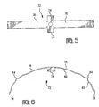
- FIGS. 5 and 6 disclose a leaf spring member 72 in accordance with a second embodiment of this invention.
- the leaf spring member 72 is stamped and formed from metal, illustratively stainless steel, as a unitary piece.
- the stamped blank is shown in FIG. 5 with oppositely extending and centrally located tabs 74.
- the tabs 74 are bent to form the central portion of the leaf spring member 72 which is mounted in the cavity 50.
- Extending outwardly in opposite directions from the tabs 74 are a pair of wings 76 having distal ends 78.
- Each of the wings 76 has a generally arcuate portion 80 and a raised portion 82. Formed as part of the raised portion 82 is a projection 84 for engaging the teeth 34.
- the coupling ring 16 may be assembled to, and disassembled from, the forward mating end of the plug shell 18. Accordingly, the coupling ring 16 does not have to pass over the entire length of cable connected to the plug subassembly 12.
- the coupling ring 16 is assembled to the plug shell 18, the inwardly extending wall 40 cannot pass the abutment 90.
- the coupling ring 16 is kept in place by a spiral ring retainer 86, which fits into an internal groove 88 in the coupling ring 16 immediately rearward of the outwardly extending wall 42 of the shell 18, to thereby prevent subsequent forward axial movement of the coupling ring 16 with respect to the shell 18.
- Table I Coupling/Decoupling Torque Shell Size Maximum Engagement and Disengagement Minimum Disengagement Newton Meters Newton Meters 8 0.9 0.2 9 0.9 0.2 10 1.4 0.2 11 1.4 0.2 12 1.8 0.2 13 1.8 0.2 14 2.3 0.4 15 2.3 0.3 16 2.7 0.4 17 2.7 0.3 18 3.2 0.6 19 3.2 0.3 20 3.6 0.7 21 3.6 0.6 22 4.1 0.8 23 4.1 0.6 24 4.1 0.8 25 4.6 0.6
- a feature of the aforedescribed design not known to be present in previous designs is that the width of the channel 44 is only slightly greater than the width of the leaf spring member 46 or 72. This provides clearance for the leaf spring member 46, 72 to be fitted within the channel 44 while at the same time preventing the leaf spring member 46, 72 from skewing. If the leaf spring member 46, 72 were to skew, its interaction with the teeth 34 would be affected, thereby impacting the effectiveness of the retardation mechanism.
- leaf spring member 46, 72 has a fixed beam at both its ends.
- both ends of the raised portion 62, 82 ride on the exterior of the shell 18 within the channel 44. This results in more control of the loading forces than in the situation where the leaf spring member is a simple beam fixed only at one end.
Landscapes
- Details Of Connecting Devices For Male And Female Coupling (AREA)
Applications Claiming Priority (2)
| Application Number | Priority Date | Filing Date | Title |
|---|---|---|---|
| US326303 | 1994-10-19 | ||
| US08/326,303 US5496189A (en) | 1994-10-19 | 1994-10-19 | Electrical connector assembly including improved decoupling retardation mechanism |
Publications (2)
| Publication Number | Publication Date |
|---|---|
| EP0708496A2 true EP0708496A2 (de) | 1996-04-24 |
| EP0708496A3 EP0708496A3 (de) | 1997-09-10 |
Family
ID=23271658
Family Applications (1)
| Application Number | Title | Priority Date | Filing Date |
|---|---|---|---|
| EP95306926A Withdrawn EP0708496A3 (de) | 1994-10-19 | 1995-09-29 | Elektrische Verbinderanordnung mit verbessertem Entkupplungsverzögerungsmechanismus |
Country Status (2)
| Country | Link |
|---|---|
| US (1) | US5496189A (de) |
| EP (1) | EP0708496A3 (de) |
Families Citing this family (17)
| Publication number | Priority date | Publication date | Assignee | Title |
|---|---|---|---|---|
| US5653605A (en) * | 1995-10-16 | 1997-08-05 | Woehl; Roger | Locking coupling |
| US5959828A (en) * | 1996-07-16 | 1999-09-28 | Hydraflow | Coupling with insulated flanges |
| US5786976A (en) * | 1996-07-16 | 1998-07-28 | Hydraflow | Coupling with hard metallic ductile conductive coating |
| US6062911A (en) * | 1997-01-31 | 2000-05-16 | The Whitaker Corporation | Low profile power connector with high-temperature resistance |
| FR2764127B1 (fr) * | 1997-05-29 | 1999-09-03 | Air Lb Gmbh | Connecteur electrique a verrouillage |
| US6059611A (en) * | 1998-05-04 | 2000-05-09 | The Whitaker Corporation | High temperature electrical connector assembly |
| EP1181475B1 (de) * | 1999-04-30 | 2005-09-28 | Crane-Resistoflex | Sicherung für überwurfmutter |
| DE10032417A1 (de) * | 2000-07-04 | 2002-01-17 | Hypertac Gmbh | Elektrischer Steckverbinder |
| US7156424B2 (en) * | 2004-03-05 | 2007-01-02 | Parker-Hannifin Corporation | Coupling assembly with retention mechanism |
| US7571937B2 (en) | 2004-09-10 | 2009-08-11 | Sps Technologies, Llc | Fluid coupling assembly with integral retention mechanism |
| US7165987B2 (en) * | 2004-09-28 | 2007-01-23 | Frank Chin-Hwan Kim | Industrial connector assembly |
| DE102005052764B4 (de) * | 2005-11-04 | 2007-12-06 | Tyco Electronics Amp Gmbh | Verbindungsanordnung mit einem Verriegelungsmechanismus sowie Sicherungselement für eine derartige Verbindungsanordnung |
| USD630305S1 (en) | 2009-02-03 | 2011-01-04 | Lasco Fittings, Inc. | Fitting |
| US8550843B2 (en) * | 2010-11-22 | 2013-10-08 | Andrew Llc | Tabbed connector interface |
| US9397441B2 (en) * | 2013-03-15 | 2016-07-19 | Cinch Connections, Inc. | Connector with anti-decoupling mechanism |
| US9666973B1 (en) * | 2016-06-10 | 2017-05-30 | Amphenol Corporation | Self-locking connector coupling |
| CA2950368C (en) * | 2016-12-02 | 2026-04-21 | Rd Scan Holdings Inc. | Lock for an explosion proof connector |
Citations (1)
| Publication number | Priority date | Publication date | Assignee | Title |
|---|---|---|---|---|
| US4648670A (en) | 1980-05-07 | 1987-03-10 | Allied Corporation | Electrical connector assembly having anti-decoupling mechanism |
Family Cites Families (23)
| Publication number | Priority date | Publication date | Assignee | Title |
|---|---|---|---|---|
| US3594700A (en) * | 1969-08-20 | 1971-07-20 | Pyle National Co | Electrical connector with threaded coupling nut lock |
| US3892458A (en) * | 1973-04-04 | 1975-07-01 | Deutsch Co Elec Comp | Coupling for electrical connector or the like |
| CA1070792A (en) * | 1976-07-26 | 1980-01-29 | Earl A. Cooper | Electrical connector and frequency shielding means therefor and method of making same |
| US4074927A (en) * | 1976-07-26 | 1978-02-21 | Automation Industries, Inc. | Electrical connector with insert member retaining means |
| US4109990A (en) * | 1977-05-26 | 1978-08-29 | The Bendix Corporation | Electrical connector assembly having anti-decoupling mechanism |
| US4165910A (en) * | 1977-10-25 | 1979-08-28 | Bunker Ramo Corporation | Electrical connector |
| US4268103A (en) * | 1979-02-02 | 1981-05-19 | The Bendix Corporation | Electrical connector assembly having anti-decoupling mechanism |
| US4239314A (en) * | 1979-04-11 | 1980-12-16 | Bunker Ramo Corporation | Electrical connector |
| US4277125A (en) * | 1979-07-12 | 1981-07-07 | Automation Industries, Inc. | Enhanced detent guide track with dog-leg |
| US4291933A (en) * | 1980-02-11 | 1981-09-29 | Akzona Incorporated | Electrical connector having improved non-decoupling mechanism |
| US4484790A (en) * | 1983-03-30 | 1984-11-27 | The Bendix Corporation | Anti-decoupling device for an electrical connector |
| US4487470A (en) * | 1983-05-11 | 1984-12-11 | The Bendix Corporation | Anti-decoupling mechanism for an electrical connector assembly |
| US4536048A (en) * | 1983-05-11 | 1985-08-20 | Allied Corporation | Anti-decoupling mechanism for an electrical connector assembly |
| US4519661A (en) * | 1983-12-09 | 1985-05-28 | Allied Corporation | Connector assembly having an anti-decoupling mechanism |
| US4588245A (en) * | 1984-08-23 | 1986-05-13 | Flight Connector Corporation | Self-locking coupling nut |
| FR2587552B1 (fr) * | 1985-09-13 | 1987-12-18 | Socapex | Connecteur electrique comportant un dispositif anti-deverrouillage |
| US4793821A (en) * | 1986-01-17 | 1988-12-27 | Engineered Transitions Company, Inc. | Vibration resistant electrical coupling |
| US4834667A (en) * | 1986-02-24 | 1989-05-30 | Engineered Transitions Co., Inc. | Vibration resistant electrical coupling |
| GB8612963D0 (en) * | 1986-05-28 | 1986-07-02 | Thorn Emi Electrical Component | Electrical connectors |
| US4726782A (en) * | 1987-01-05 | 1988-02-23 | G & H Technology, Inc. | Anti-decoupling device for an electrical connector |
| US5082454A (en) * | 1989-09-28 | 1992-01-21 | Joslyn Corporation | Two-piece retaining ring |
| US5046964A (en) * | 1989-10-10 | 1991-09-10 | Itt Corporation | Hybrid connector |
| US4984995A (en) * | 1989-11-13 | 1991-01-15 | Icore International, Inc. | Anti-decoupling device for electrical conduit connector |
-
1994
- 1994-10-19 US US08/326,303 patent/US5496189A/en not_active Expired - Lifetime
-
1995
- 1995-09-29 EP EP95306926A patent/EP0708496A3/de not_active Withdrawn
Patent Citations (1)
| Publication number | Priority date | Publication date | Assignee | Title |
|---|---|---|---|---|
| US4648670A (en) | 1980-05-07 | 1987-03-10 | Allied Corporation | Electrical connector assembly having anti-decoupling mechanism |
Also Published As
| Publication number | Publication date |
|---|---|
| EP0708496A3 (de) | 1997-09-10 |
| US5496189A (en) | 1996-03-05 |
Similar Documents
| Publication | Publication Date | Title |
|---|---|---|
| US5496189A (en) | Electrical connector assembly including improved decoupling retardation mechanism | |
| US5456611A (en) | Mini-UHF snap-on plug | |
| US4462653A (en) | Electrical connector assembly | |
| US5096444A (en) | Flat F-port connector | |
| US3892458A (en) | Coupling for electrical connector or the like | |
| US4938718A (en) | Cylindrical connector keying means | |
| US6152753A (en) | Anti-decoupling arrangement for an electrical connector | |
| US4165910A (en) | Electrical connector | |
| US4588246A (en) | Anti-decoupling mechanism for an electrical connector assembly | |
| US4239314A (en) | Electrical connector | |
| EP0052530B1 (de) | Kupplungsring eines elektrischen Verbinders mit angeformter Feder | |
| US6361348B1 (en) | Right angle, snap on coaxial electrical connector | |
| EP0893852B1 (de) | Verbinder mit lösbarem Befestigungsflansch | |
| US6123563A (en) | Anti-decoupling arrangement for an electrical connector | |
| US4648670A (en) | Electrical connector assembly having anti-decoupling mechanism | |
| US4552427A (en) | Self-locking connector | |
| US4588245A (en) | Self-locking coupling nut | |
| US4484790A (en) | Anti-decoupling device for an electrical connector | |
| US4508407A (en) | Self-locking connector | |
| US4497530A (en) | Electrical connector having a coupling indicator | |
| EP0053050A1 (de) | Kupplungsstift für einen elektrischen Verbinder | |
| US20020058437A1 (en) | G-load coupling nut | |
| JPH0670908B2 (ja) | 電気コネクタ | |
| EP0234351A1 (de) | Entkopplungswiderstehende und EMI geschirmte Mittel für eine elektrische Steckverbinderanordnung | |
| US4483579A (en) | Electrical connector having improved coupling ring |
Legal Events
| Date | Code | Title | Description |
|---|---|---|---|
| PUAI | Public reference made under article 153(3) epc to a published international application that has entered the european phase |
Free format text: ORIGINAL CODE: 0009012 |
|
| AK | Designated contracting states |
Kind code of ref document: A2 Designated state(s): DE FR GB |
|
| PUAL | Search report despatched |
Free format text: ORIGINAL CODE: 0009013 |
|
| AK | Designated contracting states |
Kind code of ref document: A3 Designated state(s): DE FR GB |
|
| 17P | Request for examination filed |
Effective date: 19980227 |
|
| 17Q | First examination report despatched |
Effective date: 19990520 |
|
| STAA | Information on the status of an ep patent application or granted ep patent |
Free format text: STATUS: THE APPLICATION IS DEEMED TO BE WITHDRAWN |
|
| 18D | Application deemed to be withdrawn |
Effective date: 19991001 |