EP0247347B1 - Durchflusskontrollventil - Google Patents
Durchflusskontrollventil Download PDFInfo
- Publication number
- EP0247347B1 EP0247347B1 EP87105616A EP87105616A EP0247347B1 EP 0247347 B1 EP0247347 B1 EP 0247347B1 EP 87105616 A EP87105616 A EP 87105616A EP 87105616 A EP87105616 A EP 87105616A EP 0247347 B1 EP0247347 B1 EP 0247347B1
- Authority
- EP
- European Patent Office
- Prior art keywords
- rod
- disk
- rollable
- handle
- tubular portion
- Prior art date
- Legal status (The legal status is an assumption and is not a legal conclusion. Google has not performed a legal analysis and makes no representation as to the accuracy of the status listed.)
- Expired - Lifetime
Links
- 239000012530 fluid Substances 0.000 title description 4
- 238000007789 sealing Methods 0.000 claims description 10
- 230000000284 resting effect Effects 0.000 abstract 1
- 238000007373 indentation Methods 0.000 description 2
- 238000012856 packing Methods 0.000 description 2
- 238000005299 abrasion Methods 0.000 description 1
- 238000010276 construction Methods 0.000 description 1
- 239000000428 dust Substances 0.000 description 1
- 230000002035 prolonged effect Effects 0.000 description 1
Images

Classifications
-
- G—PHYSICS
- G05—CONTROLLING; REGULATING
- G05D—SYSTEMS FOR CONTROLLING OR REGULATING NON-ELECTRIC VARIABLES
- G05D19/00—Control of mechanical oscillations, e.g. of amplitude, of frequency, of phase
-
- F—MECHANICAL ENGINEERING; LIGHTING; HEATING; WEAPONS; BLASTING
- F16—ENGINEERING ELEMENTS AND UNITS; GENERAL MEASURES FOR PRODUCING AND MAINTAINING EFFECTIVE FUNCTIONING OF MACHINES OR INSTALLATIONS; THERMAL INSULATION IN GENERAL
- F16K—VALVES; TAPS; COCKS; ACTUATING-FLOATS; DEVICES FOR VENTING OR AERATING
- F16K31/00—Actuating devices; Operating means; Releasing devices
- F16K31/44—Mechanical actuating means
- F16K31/52—Mechanical actuating means with crank, eccentric, or cam
- F16K31/524—Mechanical actuating means with crank, eccentric, or cam with a cam
- F16K31/52408—Mechanical actuating means with crank, eccentric, or cam with a cam comprising a lift valve
-
- F—MECHANICAL ENGINEERING; LIGHTING; HEATING; WEAPONS; BLASTING
- F16—ENGINEERING ELEMENTS AND UNITS; GENERAL MEASURES FOR PRODUCING AND MAINTAINING EFFECTIVE FUNCTIONING OF MACHINES OR INSTALLATIONS; THERMAL INSULATION IN GENERAL
- F16K—VALVES; TAPS; COCKS; ACTUATING-FLOATS; DEVICES FOR VENTING OR AERATING
- F16K31/00—Actuating devices; Operating means; Releasing devices
- F16K31/44—Mechanical actuating means
- F16K31/52—Mechanical actuating means with crank, eccentric, or cam
- F16K31/524—Mechanical actuating means with crank, eccentric, or cam with a cam
-
- F—MECHANICAL ENGINEERING; LIGHTING; HEATING; WEAPONS; BLASTING
- F16—ENGINEERING ELEMENTS AND UNITS; GENERAL MEASURES FOR PRODUCING AND MAINTAINING EFFECTIVE FUNCTIONING OF MACHINES OR INSTALLATIONS; THERMAL INSULATION IN GENERAL
- F16K—VALVES; TAPS; COCKS; ACTUATING-FLOATS; DEVICES FOR VENTING OR AERATING
- F16K31/00—Actuating devices; Operating means; Releasing devices
- F16K31/44—Mechanical actuating means
- F16K31/56—Mechanical actuating means without stable intermediate position, e.g. with snap action
Definitions
- the present invention relates to a flow control valve according to the preamble of claim 1.
- Such a flow control valve is known from AT-B-290 233.
- This valve has a one-piece valve rod for axial movement within a tubular portion, which is connected with a housing having a disk seat. Said rod bears on the lower end a disk adapted to engage with said disk seat.
- two rollers are pivoted each on horizontal axis.
- a handle is provided on the top of the flow control valve covering the top of the valve rod. On the inside of the handle there is a slanting guide surface, to which the rollers are in contact.
- the valve rod is surrounded by a coil spring for biasing the valve rod and the rollers to said guide surface. By turning the handle the valve rod will be moved in axial direction. For closing the valve, the valve rod is moved down against the force of the coil spring.
- the pressing contact between the disk and the disk seat depends on the force, with which the handle will be turned. If this force is not sufficient, the valve is not closed com- prehensivly and leckage appears. On the other side the rubber sealing of the disk will be weakened if the force for turning the handle is too much.
- valve rod is sealed only by a packing. Therefore, also in opening position leckage will occur. Namely, the pressing contact between the packing and the valve rod must not be too much, otherwise the coil spring may be to weak as to move the valve rod in upward direction.
- a flow control valve according to the preamble of claim 1, which comprises the features m) to q) in its characterizing part. Due to this design, the disk and the disk seat are subjected only by the force of the coil spring. Therefore the force is not greater than is needed. This greatly reduces the wear of or damage to the seal face, further eliminating the likely- hood that the handle closing position will change owing to damage or indentation of the seal face or to a dimensional error. Since the valve rod is divided in a first rod part and a second rod part connected together rotatable relativ and in aling- ment to each other it was possible to dispose a special sealing between the valve rod and the housing.
- this is a bellows type sealing tube welded at one end to the second rod part and its other end to the tubular portion. So also in the opening position of the valve rod no leckage can occur, although the first rod part of the valve rod is easy rotatable.
- the subclaim discloses a special design of the present invention.
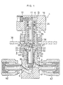
- the flow control device 1 shown comprises a case 2 which has a fluid flow channel 6, a disk seat 7 and a tubular portion 5 having an externally threaded upper end portion 14.
- a closure 3 having a top wall 4 is mounted on the upper end of the tubular portion 5 by a connecting nut 8.
- a spindle 9 comprises an upper spindle member 9a extending through the closure top wall 4 and having an upper end portion projecting upward therefrom, and a lower spindle member 9b rotatably connected to the lower, end of the upper spindle member 9a by a connecting pin 29 and having a disk 11 at its lower end.
- An annular spring support 12 is attached to the lower end of the upper spindle member 9a.
- a coiled spring 13 provided around the upper spindle member 9a is interposed between the spring support 12 and the closure top wall 4 for biasing the spindle 9 downward, whereby the disk 11 at the lower end of the spindle 9 is pressed into contact with the disk seat 7.
- a short cylindrical housing 15 having a top wall 16 is fitted over the upper end portion of the upper spindle member 9a.
- a spring pin 17 is inserted in a bore horizontally extending straight through the upper end portion of the upper member 9a and the top wall 16 of the housing 15, whereby the housing 15 is held to the upper spindle member 9a unremowably.
- a handle 18, which is generally elliptical when seen from above, is fitted over the housing 15 and fixed thereto with a bolt 19 having a hexagonal socket head.
- the spring support 12 at the lower end of the upper spindle member 9a has a downwardly open socket 26 having the head 27 of the lower spindle member 9b inserted therein.
- An annular groove 28 is formed in the head 27 of the lower spindle member 9b.
- the aforementioned connecting pin 29, extending horizontally is partly fitted in the groove 28 and supported at its opposite ends by the spring support 12, whereby the lower spindle member 9b is connected to the upper spindle member 9a rotatably relative
- a pair of rollable members 20, each comprising a ball bearing, for lifting and lowering the spindle 9 are mounted in a vertical position by a horizontal pin 24 on the upper spindle member 9a at a portion thereof close to its upper end. These rollable members 20 rest on the upper surface of the closure top wall 4.
- the top wall 4 of the closure 3 is formed in its upper surface with a lower recessed portion 21 for the rollable member 20 to partly fit in, an upper recessed portion 22 positioned 90 degrees away from the portion 21 about the axis of the closure 3 for the rollable member 20 to partly fit in, and a slanting guide face 23 between the two recessed portions 21, 22.
- the top wall surface has another set of such recessed portions 21, 22 and guide face 23.
- the spindle 9 may be provided with only one rollable member 20.
- the angle of rotation of the handle 18 can be determined suitably by spacing the lower and upper recessed portions 21, 22 by a suitable distance, and at least one set of lower and upper recesses 21, 22 and intermediate slanting guide face 23 may be formed.
- An annular stepped portion 31 is formed in the upper end of the tubular portion 5 of the case 2 inside thereof.
- a ring 32 for attaching a sealing tube 40 in the form of bellows is fitted to the stepped portion 31 with a gasket 33 provided therebetween.
- the lower end of the closure 3 is placed on the ring 32.
- the closure 3 and the tubular portion 5 are joined to each other by the connecting nut 8, with a gasket 34 interposed between a flange 30 on the closure 3 and the upper end of the tubular portion 5.
- a tubular portion 35, externally threaded as at 36, extends upward from the upper end of the connecting nut 8.
- a nut 37 for fastening the flow control device 1 to a panel 38 is screwed on the externally threaded portion 36.
- the lower spindle member 9b has an annular projection 39 close to its lower end for attaching the sealing tube 40.
- the bellows-shaped sealing tube 40 is fitted around the lower spindle member 9b and welded at its upper and lower ends to the ring 32 and to the projection 39.
- a pipe connecting sleeve 41 having a union nut 42 is attached to each of opposite side walls of the case 2.
- the rollable members 20 mounted on the spindle 9 are fitted in the lower recesses 21 in the upper surface of the closure top wall 4.
- the handle 18 is rotated counterclockwise through 90 degrees from this state to the solid- line position of Fig. 2
- the upper spindle member 9a rotates with the handle 18, causing the two rollable members 20 to ascend the slanting guide faces 23 and fit into the upper recessed portions 22 and thereby lifting the spindle 9 against the force of the spring 13. Consequently, the disk 11 is moved away from its seat 7 to open the fluid flow channel 6.
- the channel 6 is closable from this state by reversely rotating the handle 18 clockwise through 90 degrees.
- the flow channel 6 is closed by the device 1 under the action of the spring 13 instead of resorting to the screwing action utilized in the conventional device, with the result that the disk 11 and the sealing face of the seat 7 are not subjected to a force greater than is needed.
- the rollable member 20 is adapted to fit into the lower and upper recessed portions 21, 22 which are similar to the member 20 in radius of curvature, a click and feel to the handle gripping hand indicate that the member 20 has been brought to its stopped position.
- the bearing serving as the rollable member 20 according to the present embodiment is especially less prone to abrasion and serviceable for a prolonged period of time.
- the flow channel 6 is openable by rotating the handle 18 in a direction to compress the spring 13, so that the handle 18 is heavier when it is rotated toward the opening direction. This obviates the possible damage to the bellows-shaped sealing tube 40 provided around the lower spindle member 9b.
- the handle 18 is fixed by the bolt 19 to the housing 15, which in turn is attached to the upper end of the spindle by a spring pin 17. Whereas the bolt heretofore directly screwed into the spindle is likely to cause damage to the spindle, the above arrangement obviates the possibility of causing such damage, holding the handle 18 in position without any play or slipping off even when it is used repeatedly.
- the ball bearing serving as the rollable member 20 is covered with the housing 15 and therefore remains free from dust or the like when the device 1 is being attached to the panel 38, hence safety and no likelihood of some parts becoming lost.
- the rollable member 20, which comprises a ball bearing according to the embodiment described, may be some other roller.
Landscapes
- Engineering & Computer Science (AREA)
- General Engineering & Computer Science (AREA)
- Mechanical Engineering (AREA)
- Physics & Mathematics (AREA)
- General Physics & Mathematics (AREA)
- Automation & Control Theory (AREA)
- Mechanically-Actuated Valves (AREA)
- Lift Valve (AREA)
- Preventing Unauthorised Actuation Of Valves (AREA)
- Closures For Containers (AREA)
- Fluid-Driven Valves (AREA)
- Vehicle Body Suspensions (AREA)
Claims (2)
Priority Applications (1)
| Application Number | Priority Date | Filing Date | Title |
|---|---|---|---|
| AT87105616T ATE50343T1 (de) | 1986-04-18 | 1987-04-15 | Durchflusskontrollventil. |
Applications Claiming Priority (2)
| Application Number | Priority Date | Filing Date | Title |
|---|---|---|---|
| JP90629/86 | 1986-04-18 | ||
| JP61090629A JPH0792164B2 (ja) | 1986-04-18 | 1986-04-18 | 流動制御機器 |
Publications (2)
| Publication Number | Publication Date |
|---|---|
| EP0247347A1 EP0247347A1 (de) | 1987-12-02 |
| EP0247347B1 true EP0247347B1 (de) | 1990-02-07 |
Family
ID=14003775
Family Applications (1)
| Application Number | Title | Priority Date | Filing Date |
|---|---|---|---|
| EP87105616A Expired - Lifetime EP0247347B1 (de) | 1986-04-18 | 1987-04-15 | Durchflusskontrollventil |
Country Status (7)
| Country | Link |
|---|---|
| US (1) | US4804164A (de) |
| EP (1) | EP0247347B1 (de) |
| JP (1) | JPH0792164B2 (de) |
| KR (1) | KR930003055B1 (de) |
| AT (1) | ATE50343T1 (de) |
| CA (1) | CA1299558C (de) |
| DE (1) | DE3761702D1 (de) |
Families Citing this family (30)
| Publication number | Priority date | Publication date | Assignee | Title |
|---|---|---|---|---|
| US4995589A (en) * | 1990-01-29 | 1991-02-26 | Sequioa Controls Company, Ltd. | Bellows valve |
| USD331449S (en) | 1990-01-29 | 1992-12-01 | Sequoia Controls Co., Ltd. | Bellows valve |
| JP3106366B2 (ja) * | 1991-02-26 | 2000-11-06 | 清原 まさ子 | 流体制御器 |
| US6133022A (en) * | 1992-07-09 | 2000-10-17 | Nl Technologies, Limited | Automated sample extractor or feeder/inoculator for bioreactors and similar equipment |
| US6821773B1 (en) | 1992-07-09 | 2004-11-23 | Nl Technologies, Ltd. | Drainable ferrule valve design |
| US5296197A (en) * | 1992-07-09 | 1994-03-22 | Nl Technologies, Limited | Automated sample extractor or feeder/inoculator for bioreactors and similar equipment |
| TW244368B (de) * | 1992-11-06 | 1995-04-01 | Fujikin Kk | |
| US5725198A (en) * | 1996-02-20 | 1998-03-10 | Ohmeda Inc. | Non-rotating needle valve |
| US6065694A (en) * | 1997-04-02 | 2000-05-23 | Staar S.A. | Flow limiter |
| JP4189558B2 (ja) * | 1998-06-08 | 2008-12-03 | 株式会社フジキン | 流体制御器 |
| US7389792B2 (en) * | 1998-12-24 | 2008-06-24 | Nl Technologies, Ltd. | Dip tube valve assembly |
| EP1148949A4 (de) | 1998-12-24 | 2006-05-10 | Nl Technologies Ltd | Tauchrohr-ventil-ensemble |
| US6311948B1 (en) * | 2000-03-24 | 2001-11-06 | T&S Brass And Bronze Works, Inc. | Fluid valve assembly |
| CH695247A5 (de) | 2000-06-16 | 2006-02-15 | Balzers Hochvakuum | Vakuumventil |
| KR100914852B1 (ko) * | 2005-04-13 | 2009-09-04 | 씨케이디 가부시키 가이샤 | 오동작방지 수동밸브 |
| WO2006112011A1 (ja) * | 2005-04-13 | 2006-10-26 | Ckd Corporation | 誤動作防止手動弁 |
| US7237473B2 (en) | 2005-07-21 | 2007-07-03 | Bendix Commercial Vehicle Systems | Actuator for pneumatic valve |
| US8434793B2 (en) * | 2007-07-19 | 2013-05-07 | Swagelok Company | Coated seals |
| US8327880B2 (en) * | 2009-09-29 | 2012-12-11 | Honeywell International Inc. | Sensor replacement valve |
| CN102155580B (zh) * | 2011-04-12 | 2012-08-29 | 浙江超达阀门股份有限公司 | 一种带波纹管密封的阀门 |
| US9454158B2 (en) | 2013-03-15 | 2016-09-27 | Bhushan Somani | Real time diagnostics for flow controller systems and methods |
| JP2015057563A (ja) * | 2013-08-12 | 2015-03-26 | 株式会社テクノ高槻 | 弁構造 |
| US9885427B2 (en) * | 2014-06-06 | 2018-02-06 | Ckd Corporation | Manual opening/closing valve |
| KR20170064222A (ko) * | 2015-12-01 | 2017-06-09 | 티에스케이 주식회사 | 벨로우즈형 스팀 트랩 |
| US10983538B2 (en) | 2017-02-27 | 2021-04-20 | Flow Devices And Systems Inc. | Systems and methods for flow sensor back pressure adjustment for mass flow controller |
| WO2019161259A1 (en) | 2018-02-15 | 2019-08-22 | Jacobsen Innovations, Inc. | Digital hydraulic system |
| CA3088388C (en) * | 2019-05-17 | 2022-05-17 | Malcolm Macduff | Quarter-turn pin-value actuator |
| LU101358B1 (en) * | 2019-08-20 | 2021-03-04 | Luxembourg Patent Co | Gas cylinder valve with radially extending operating handle |
| DE102020120439A1 (de) * | 2020-08-03 | 2022-02-03 | Focke & Co. (Gmbh & Co. Kg) | Ventil für fließfähige Medien |
| IT202100015410A1 (it) * | 2021-06-11 | 2022-12-11 | Cavagna Group Spa | Valvola per fluidi in pressione |
Family Cites Families (12)
| Publication number | Priority date | Publication date | Assignee | Title |
|---|---|---|---|---|
| US1155576A (en) * | 1914-11-09 | 1915-10-05 | Gilbert William Isley | Valve. |
| US2105864A (en) * | 1935-11-30 | 1938-01-18 | Saunders Philip Keith | Fluid-controlling valve |
| US2114139A (en) * | 1937-01-11 | 1938-04-12 | C A Dunham Co | Regulating radiator valve |
| US2933283A (en) * | 1957-10-19 | 1960-04-19 | Kreis Philipp | Cut-off valve |
| US3127786A (en) * | 1960-12-13 | 1964-04-07 | Wooley William Hubert | Detent for a self-closing water faucet |
| US3164173A (en) * | 1963-03-18 | 1965-01-05 | Albert L Semon | Quick-opening valves |
| AT290233B (de) * | 1967-05-12 | 1971-05-25 | Ohg Edmondo Balsamo Soc R L | Schnellschlußkopf als Oberteil zu einem Schnellschlußventil |
| US3550903A (en) * | 1967-06-27 | 1970-12-29 | Huntington Mechanical Lab | Valve and valve closure mechanism |
| US3787023A (en) * | 1971-08-05 | 1974-01-22 | Nupro Co | Bellows valve |
| US4201366A (en) * | 1978-03-13 | 1980-05-06 | Danko Oliver L | Bellows valve |
| JPS5712778Y2 (de) * | 1979-06-07 | 1982-03-13 | ||
| JPS616389Y2 (de) * | 1981-02-09 | 1986-02-26 |
-
1986
- 1986-04-18 JP JP61090629A patent/JPH0792164B2/ja not_active Expired - Fee Related
-
1987
- 1987-04-11 KR KR1019870003478A patent/KR930003055B1/ko not_active Expired - Lifetime
- 1987-04-15 EP EP87105616A patent/EP0247347B1/de not_active Expired - Lifetime
- 1987-04-15 DE DE8787105616T patent/DE3761702D1/de not_active Expired - Lifetime
- 1987-04-15 AT AT87105616T patent/ATE50343T1/de not_active IP Right Cessation
- 1987-04-21 CA CA000535080A patent/CA1299558C/en not_active Expired - Lifetime
-
1988
- 1988-07-08 US US07/217,097 patent/US4804164A/en not_active Expired - Lifetime
Also Published As
| Publication number | Publication date |
|---|---|
| KR930003055B1 (ko) | 1993-04-17 |
| KR870010428A (ko) | 1987-11-30 |
| JPS62246677A (ja) | 1987-10-27 |
| ATE50343T1 (de) | 1990-02-15 |
| JPH0792164B2 (ja) | 1995-10-09 |
| US4804164A (en) | 1989-02-14 |
| EP0247347A1 (de) | 1987-12-02 |
| DE3761702D1 (de) | 1990-03-15 |
| CA1299558C (en) | 1992-04-28 |
Similar Documents
| Publication | Publication Date | Title |
|---|---|---|
| US4804164A (en) | Flow control device | |
| US4616804A (en) | Gate valve | |
| RU2259507C2 (ru) | Полушаровой клапан | |
| US4917354A (en) | Dual action ball valve | |
| US3542331A (en) | Valves | |
| EP0597424B1 (de) | Durchflusskontrollvorrichtung | |
| US4684037A (en) | Perfected mechanical control device for ball valve type valve systems | |
| EP0501328B1 (de) | Durchflussregler | |
| US5685339A (en) | Hot/cold water flowrate control device | |
| US3941351A (en) | Ball type valve with high pressure sealing capability | |
| US3342453A (en) | Stop valve | |
| JPH0238765A (ja) | 弁閉止体を調整するための方法と装置 | |
| US4322056A (en) | Positive closure disc valve | |
| GB2062810A (en) | On-off spring valve for fluids | |
| GB2106615A (en) | Beertrap | |
| TWI776936B (zh) | 閥上部 | |
| KR200264338Y1 (ko) | 파이프용 슬라이드식 차단밸브 | |
| JPH0542303Y2 (de) | ||
| JPH0210391Y2 (de) | ||
| JPS6040942Y2 (ja) | 回転弁の駆動機構 | |
| JP2538993Y2 (ja) | ボールバルブ | |
| KR20010106355A (ko) | 파이프용 슬라이드식 차단밸브 | |
| JPS583980Y2 (ja) | 仕切弁 | |
| JPS60521Y2 (ja) | 球形弁 | |
| JPH0429163Y2 (de) |
Legal Events
| Date | Code | Title | Description |
|---|---|---|---|
| PUAI | Public reference made under article 153(3) epc to a published international application that has entered the european phase |
Free format text: ORIGINAL CODE: 0009012 |
|
| AK | Designated contracting states |
Kind code of ref document: A1 Designated state(s): AT BE CH DE FR GB IT LI NL SE |
|
| 17P | Request for examination filed |
Effective date: 19871109 |
|
| 17Q | First examination report despatched |
Effective date: 19881004 |
|
| GRAA | (expected) grant |
Free format text: ORIGINAL CODE: 0009210 |
|
| AK | Designated contracting states |
Kind code of ref document: B1 Designated state(s): AT BE CH DE FR GB IT LI NL SE |
|
| REF | Corresponds to: |
Ref document number: 50343 Country of ref document: AT Date of ref document: 19900215 Kind code of ref document: T |
|
| REF | Corresponds to: |
Ref document number: 3761702 Country of ref document: DE Date of ref document: 19900315 |
|
| ET | Fr: translation filed | ||
| ITF | It: translation for a ep patent filed | ||
| PLBE | No opposition filed within time limit |
Free format text: ORIGINAL CODE: 0009261 |
|
| STAA | Information on the status of an ep patent application or granted ep patent |
Free format text: STATUS: NO OPPOSITION FILED WITHIN TIME LIMIT |
|
| 26N | No opposition filed | ||
| ITTA | It: last paid annual fee | ||
| EAL | Se: european patent in force in sweden |
Ref document number: 87105616.4 |
|
| REG | Reference to a national code |
Ref country code: GB Ref legal event code: IF02 |
|
| PGFP | Annual fee paid to national office [announced via postgrant information from national office to epo] |
Ref country code: DE Payment date: 20060324 Year of fee payment: 20 |
|
| PGFP | Annual fee paid to national office [announced via postgrant information from national office to epo] |
Ref country code: NL Payment date: 20060419 Year of fee payment: 20 |
|
| PGFP | Annual fee paid to national office [announced via postgrant information from national office to epo] |
Ref country code: FR Payment date: 20060420 Year of fee payment: 20 |
|
| PGFP | Annual fee paid to national office [announced via postgrant information from national office to epo] |
Ref country code: SE Payment date: 20060424 Year of fee payment: 20 Ref country code: AT Payment date: 20060424 Year of fee payment: 20 |
|
| PGFP | Annual fee paid to national office [announced via postgrant information from national office to epo] |
Ref country code: CH Payment date: 20060425 Year of fee payment: 20 |
|
| PGFP | Annual fee paid to national office [announced via postgrant information from national office to epo] |
Ref country code: GB Payment date: 20060426 Year of fee payment: 20 Ref country code: BE Payment date: 20060426 Year of fee payment: 20 |
|
| PGFP | Annual fee paid to national office [announced via postgrant information from national office to epo] |
Ref country code: IT Payment date: 20060430 Year of fee payment: 20 |
|
| PG25 | Lapsed in a contracting state [announced via postgrant information from national office to epo] |
Ref country code: NL Free format text: LAPSE BECAUSE OF EXPIRATION OF PROTECTION Effective date: 20070415 |
|
| REG | Reference to a national code |
Ref country code: GB Ref legal event code: PE20 |
|
| REG | Reference to a national code |
Ref country code: CH Ref legal event code: PL |
|
| NLV7 | Nl: ceased due to reaching the maximum lifetime of a patent |
Effective date: 20070415 |
|
| EUG | Se: european patent has lapsed | ||
| PG25 | Lapsed in a contracting state [announced via postgrant information from national office to epo] |
Ref country code: GB Free format text: LAPSE BECAUSE OF EXPIRATION OF PROTECTION Effective date: 20070414 |
|
| BE20 | Be: patent expired |
Owner name: *FUJIKIN INTERNATIONAL INC. Effective date: 20070415 |