EP0247406A1 - Marmite à pression munie d'un joint d'étanchéité - Google Patents
Marmite à pression munie d'un joint d'étanchéité Download PDFInfo
- Publication number
- EP0247406A1 EP0247406A1 EP87106633A EP87106633A EP0247406A1 EP 0247406 A1 EP0247406 A1 EP 0247406A1 EP 87106633 A EP87106633 A EP 87106633A EP 87106633 A EP87106633 A EP 87106633A EP 0247406 A1 EP0247406 A1 EP 0247406A1
- Authority
- EP
- European Patent Office
- Prior art keywords
- container
- lid
- sealing lip
- sliding element
- pressure cooker
- Prior art date
- Legal status (The legal status is an assumption and is not a legal conclusion. Google has not performed a legal analysis and makes no representation as to the accuracy of the status listed.)
- Granted
Links
- 238000007789 sealing Methods 0.000 title claims abstract description 53
- 229920001971 elastomer Polymers 0.000 claims description 2
- 239000000806 elastomer Substances 0.000 claims description 2
- 239000004033 plastic Substances 0.000 claims description 2
- 238000003825 pressing Methods 0.000 claims description 2
- 229920002379 silicone rubber Polymers 0.000 claims description 2
- 239000004945 silicone rubber Substances 0.000 claims description 2
- 229910001220 stainless steel Inorganic materials 0.000 claims 1
- 239000010935 stainless steel Substances 0.000 claims 1
- 230000000994 depressogenic effect Effects 0.000 description 6
- 238000010411 cooking Methods 0.000 description 5
- 239000000463 material Substances 0.000 description 5
- 238000000034 method Methods 0.000 description 3
- 239000002184 metal Substances 0.000 description 2
- 238000004026 adhesive bonding Methods 0.000 description 1
- 230000004888 barrier function Effects 0.000 description 1
- 239000011324 bead Substances 0.000 description 1
- 230000015572 biosynthetic process Effects 0.000 description 1
- 230000000295 complement effect Effects 0.000 description 1
- 230000000694 effects Effects 0.000 description 1
- 238000005538 encapsulation Methods 0.000 description 1
- 230000003993 interaction Effects 0.000 description 1
- 238000004519 manufacturing process Methods 0.000 description 1
- 229920003051 synthetic elastomer Polymers 0.000 description 1
- 239000005061 synthetic rubber Substances 0.000 description 1
- 238000004073 vulcanization Methods 0.000 description 1
Images





Classifications
-
- A—HUMAN NECESSITIES
- A47—FURNITURE; DOMESTIC ARTICLES OR APPLIANCES; COFFEE MILLS; SPICE MILLS; SUCTION CLEANERS IN GENERAL
- A47J—KITCHEN EQUIPMENT; COFFEE MILLS; SPICE MILLS; APPARATUS FOR MAKING BEVERAGES
- A47J27/00—Cooking-vessels
- A47J27/08—Pressure-cookers; Lids or locking devices specially adapted therefor
- A47J27/09—Safety devices
-
- A—HUMAN NECESSITIES
- A47—FURNITURE; DOMESTIC ARTICLES OR APPLIANCES; COFFEE MILLS; SPICE MILLS; SUCTION CLEANERS IN GENERAL
- A47J—KITCHEN EQUIPMENT; COFFEE MILLS; SPICE MILLS; APPARATUS FOR MAKING BEVERAGES
- A47J27/00—Cooking-vessels
- A47J27/08—Pressure-cookers; Lids or locking devices specially adapted therefor
-
- A—HUMAN NECESSITIES
- A47—FURNITURE; DOMESTIC ARTICLES OR APPLIANCES; COFFEE MILLS; SPICE MILLS; SUCTION CLEANERS IN GENERAL
- A47J—KITCHEN EQUIPMENT; COFFEE MILLS; SPICE MILLS; APPARATUS FOR MAKING BEVERAGES
- A47J27/00—Cooking-vessels
- A47J27/08—Pressure-cookers; Lids or locking devices specially adapted therefor
- A47J27/0804—Locking devices
- A47J27/0806—Locking devices of the bayonet-type
-
- A—HUMAN NECESSITIES
- A47—FURNITURE; DOMESTIC ARTICLES OR APPLIANCES; COFFEE MILLS; SPICE MILLS; SUCTION CLEANERS IN GENERAL
- A47J—KITCHEN EQUIPMENT; COFFEE MILLS; SPICE MILLS; APPARATUS FOR MAKING BEVERAGES
- A47J27/00—Cooking-vessels
- A47J27/08—Pressure-cookers; Lids or locking devices specially adapted therefor
- A47J27/09—Safety devices
- A47J27/092—Devices for automatically releasing pressure before opening
Definitions
- the invention relates to a pressure cooker.
- the seal is provided with radial ribs which have no function in the closed state, but when the cover is pressed down, the seal is lifted from the container or from the cover like a lever bearing. The overpressure can be released with one hand.
- the object of the invention is to provide such a one-handed steam pressure cooker, the un is complex to produce, is subject to less wear and allows complete and rapid release of the excess pressure before opening the pot.
- the pressure cooker according to the invention has the features defined in claim 1.
- the pressure cooker according to the invention can be produced without great effort because of its simple structure. Before opening, the sliding element lifts the sealing lip off the lid or container, thus allowing the excess pressure to escape quickly. Sliding element and sealing lip are hardly stressed in their interaction and are only distributed over a larger contact area, so that the A b use remains low. In the case of a seal with two sealing lips that rest on the lid or on the container, the sliding element can be combined with one of the two, as desired.
- the pressure cooker can be cylindrical or with a rectangular base.
- the sliding element facilitates the lid movement and prevents the sealing lip, which is then completely lifted, from wearing out.
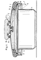
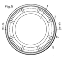
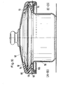
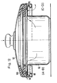
- Figures 1 to 6 show an open-topped cookware container 1 with a continuous container rim 9, from the circumference of which segment-like edge projections 4 project radially outwards.
- locks 5 and stops 6 alternately extend downward and radially outward below the container edge 9 and close to the outer edge of the edge projections 4.
- the radial extent of the locks 5 and stops 6 is essentially the same (FIGS. 1, 3 and 5); the locks 5, however, extend less far downward than the stops 6.
- the locks 5 and stops 6 each lie on the circumferential ends of the edge projections 4. They form a closing device, together with complementary devices of the cover described later.
- the lid edge 10 of a lid 2 projects beyond the cooking material container 1 on all sides.
- the lid 2 bulges slightly downwards to the lid edge 10 and then inwards to form an inwardly open channel for receiving the seal 11 to be described.
- annular straight web area 33 extends downward from the lid edge 10.
- the lid edge projections 3 protrude radially inward from the web area 33 and form circular disk segments which are complementarily similar to the container edge projections 4. If each edge of the lid projection 3 in a andlücke R 13 is between two container edge projections 4 (Fig. 3), which cover edge projections 3 may pass downwardly between the container edge 4 projections.
- the cover 2 is first, as shown in F ig. 5 and 6 ge shows, placed in any position on the edge of the food container 1.
- the lid edge protrusions 3 rest on the top of the container edge protrusions 4 facing away from the bottom of the cooking material container 1.
- the lid 2 is turned until the lid edge projections lie in the edge gaps 13 (FIG. 3) and then pressed down (FIG. 4).
- the cover edge projections 3 lie laterally on the stops 6.
- FIGS. 1 and 2 when the lid is released, it can move upwards to a limited extent until the lid edge projections 3 come into contact with the container edge projections 4 (FIG. 2). This is the operating position of the locking device of the pressure cooker.
- the cover 2 has a seal 11 which is radially inward V-shaped in cross section and thus forms two sealing lips 7, 8.
- the seal 11 extends as a closed, essentially circular profile over the entire circumference of the lid edge 10. Its one, upper sealing lip 8 lies flat against the underside of the lid 2, while its other, lower sealing lip 7 with the lid 2 removed from the lid edge 10 protrudes freely inwards and downwards. The free end of this lower sealing lip 7 rests on the container rim 9 of the cookware container 1 when the lid 2 is attached and seals the lid 2 from the cookware container 1.
- a closed ring as a sliding element 12 made of a material which, with the container 1 or cover 2, results in a sliding pairing with the lowest possible coefficient of friction, for example made of metal or hard plastic.
- the seal consists for example of an NBR elastomer or synthetic rubber, such as silicone rubber.
- the outer diameter of the sliding element is almost as large as the inner diameter of the web area 33. As a result, the sliding element 12 cannot slip out of its position between the sealing lip 7, the web area 33 and the lid edge projections 3.
- the spring force of the seal 11 would twist of the lid 2 significantly more difficult if the sealing lip 7 would abut the container rim 9.
- the much lower friction between the sliding element 12 and the container rim 9 makes it much easier to rotate the lid 2; since, in addition, the sealing lip 7 is pivoted completely away from the container edge 9, the friction between the sliding element 12 and the container edge 9 is the only counterforce when the cover 2 is rotated.
- the sliding element 12 Because of the relatively high rigidity of the sliding element 12, it can support the lower sealing lip 7 in the region of the edge gaps 13 without having to be supported on the underside itself.
- the sliding element 12 therefore helps to prevent excessive deformation of the sealing lip 7 in this area, which could lead to the pressure cooker becoming leaky.
- a safety valve arranged in the knob handle 35 of the cover 2 limits the excess pressure and comprises a valve opening 40 which forms a seat for a valve body 15.
- the valve body 15 is displaced in a vertical blind bore of the knob handle 35 Lich guided and is urged by a spring 39 to the valve opening 40 of the cover 2.
- the spring force of the spring 39 is matched to the desired operating pressure.
- the button handle 35 is provided on the underside with bores 42 into which driver pins 41 fastened to the cover 2 engage. These bores 42, just like the bores accommodating the valve body 15, are arranged eccentrically to the central axis of the knob handle 35.
- the extension 16 of the knob handle 35 forms a vapor pressure relief valve with the underside of the cover 2, which can be opened by pressing the knob handle 35.
- the button handle 35 When the cooking process is finished, the button handle 35 is depressed. Part of the overpressure initially escapes through the drain valve 16 (FIG. 4). When the button handle 35 is pressed further, the entire cover 2 is pressed down. The lower sealing lip 7 is pivoted upward like a lever about its point of contact on the sliding element 12; the remaining overpressure can escape through the marginal gaps 13, 14. Since a very large cross-section is available for this, measured at the drain valve, the pressure cooker quickly becomes completely depressurized. The cover 2 can subsequently be turned and unlocked.
- FIGS. 7 and 8 A second preferred embodiment of the pressure cooker is shown in FIGS. 7 and 8.
- the cookware container 1 has a circumferential, smooth container edge 17.
- a cover 2 comprises a hood 18 forming its main body. On its outer circumference, the hood 18 has a groove 32 which is open at the top and approximately rectangular in cross section and which is surrounded radially outwards by a second groove 34 which is open at the bottom.
- a cover ring 25 extends in a radially outward direction over both grooves 32, 34.
- clamps 19 are provided which are movable with respect to the cover 2 in its radial as well as in the circumferential direction.
- slots 27 of the brackets 19 are sliding blocks 26, which are held between the bottom of the second groove 34 and the cover ring 25.
- a horizontal locking area 29 attaches to the lower edge of the clips 19.
- a web 36 engages behind the outer edge of the container edge 17 in the locked position of the lid.
- the locking region 29 has a slot 24 through which a finger 23 of the frame ring 20 extends. As a result, the bracket 19 can only move radially.
- the seal 11 rests with an upper sealing lip 21 on the underside of the hood 18.
- a hood opening 31 is provided radially outward from the contact point between the upper sealing lip 21 and this area.
- the sliding element 12 is held in its position by the radially inward wall and the bottom of the second groove 34, by the frame ring 20 and the upper side of the upper sealing lip 21.
- the bracket 19 is in its most radially inwardly displaced position, the top of its locking area 29 is located on the lower edge 30 of the web extending downward on the outer edge of the container edge 17.
- the lid 2 Due to the internal pressure and the seal 11, the lid 2 is pushed away from the food container 1; this movement is limited by the engagement of the latch area 29 and the lower edge 30.
- the pressure cooker is first partially depressurized, as in the first embodiment.
- the sliding element 12 lever the upper sealing lip 21 off the hood 18, as shown in FIG. 8.
- the residual internal pressure by the H aubenöff- can voltages 31 to escape.
- the frame ring 20 lying flat against it is also not rotated.
- the fingers 23 prevent the clamps 19 from rotating relative to the cookware container 1, so that overall there is a rotation of the hood and cover ring 25 relative to the entirety of the cookware container 1, seal 11, frame ring 20, clamps 19 and sliding element 12.
- the sliding blocks 26 slide in the slots 27 and push the clamps 19 outwards.
- the upper edges 28 of the webs 36 of the clamps 19 are in engagement with the lower edges 30 of the web on the container edge 17.
- the lid 2 is pulled so far towards the food container 1 that the upper sealing lip 21 is in its raised position and no pressure can build up in the pot.
- the edges 28, 30 therefore act like the locks 5 of the first embodiment.
- a third preferred embodiment comprises a rectangular cookware container 50 with a rectangular lid 52.
- the lid 52 can be pushed onto or pushed off the cookware container 50 in the longitudinal direction thereof and is held on the container by a horizontal web 54 which engages under the container edge 56.
- Such a pot is known for example from DE-PS 28 01 173.
- a seal 60 is clamped to the cover 52 by a support element 72 which lies between two sealing lips 62, 64.
- Under the lower sealing lip 64 is a sliding element 100 with side lugs 68, which protrude outward through slots 58 in the edge of the cover 52 and hold the sliding element 100.
- Seal 60 and sliding element 100 follow the rectangular contour of the lid 52. Material rigidity and holding of the sliding element 100 by the lugs 68 are selected so that the lower sealing lip 64 can rest on the container edge 56 when the lid is pushed on, but on the other hand a slight snapping of the lid 52 onto the container 50 can be done.
- the sealing function of the pressure cooker during operation corresponds exactly to that already described. In the operating state, the contact of the lower sealing lip 64 on the container edge 56 prevents the internal pressure from escaping.
- the slider 100 serves as a lever bearing.
- the residual steam can escape through openings 70 in the container edge 56 (FIG. 12).
- the sliding element 100 is also provided on its side facing away from the lower sealing lip 64 with recesses 66 which, together with the slots 58, form a further possibility for the steam to escape.
- the lid 52 can then be completely pushed off the cooking material container 50, as shown in FIGS. 11 and 12.
- the sliding element can be integrated into the seal, for example by Gluing, vulcanization or partial encapsulation or even one-piece manufacture. Furthermore, it is possible to replace the sliding element with a functionally corresponding, lever-bearing-shaped formation (bead) on the lid or container edge.
Landscapes
- Engineering & Computer Science (AREA)
- Food Science & Technology (AREA)
- Cookers (AREA)
- Pressure Vessels And Lids Thereof (AREA)
Priority Applications (1)
| Application Number | Priority Date | Filing Date | Title |
|---|---|---|---|
| AT87106633T ATE55228T1 (de) | 1986-05-30 | 1987-05-07 | Dampfdruckkochtopf mit einer den topfinnenraum gegen druckabfall sichernden dichtung. |
Applications Claiming Priority (2)
| Application Number | Priority Date | Filing Date | Title |
|---|---|---|---|
| DE3618269 | 1986-05-30 | ||
| DE19863618269 DE3618269A1 (de) | 1986-05-30 | 1986-05-30 | Dampfdruckkochtopf mit einer den topfinnenraum gegen druckabfall sichernden dichtung |
Publications (2)
| Publication Number | Publication Date |
|---|---|
| EP0247406A1 true EP0247406A1 (fr) | 1987-12-02 |
| EP0247406B1 EP0247406B1 (fr) | 1990-08-08 |
Family
ID=6301985
Family Applications (1)
| Application Number | Title | Priority Date | Filing Date |
|---|---|---|---|
| EP87106633A Expired - Lifetime EP0247406B1 (fr) | 1986-05-30 | 1987-05-07 | Marmite à pression munie d'un joint d'étanchéité |
Country Status (25)
| Country | Link |
|---|---|
| US (1) | US4733795A (fr) |
| EP (1) | EP0247406B1 (fr) |
| JP (1) | JP2514609B2 (fr) |
| KR (1) | KR910006883B1 (fr) |
| AR (1) | AR243361A1 (fr) |
| AT (1) | ATE55228T1 (fr) |
| AU (1) | AU581612B2 (fr) |
| BR (1) | BR8702775A (fr) |
| CA (1) | CA1271926A (fr) |
| DD (1) | DD261091A1 (fr) |
| DE (2) | DE3618269A1 (fr) |
| DK (1) | DK170269B1 (fr) |
| ES (1) | ES2016944B3 (fr) |
| FI (1) | FI84425C (fr) |
| GR (1) | GR3000779T3 (fr) |
| HK (1) | HK18591A (fr) |
| IE (1) | IE59933B1 (fr) |
| IL (1) | IL82708A0 (fr) |
| IN (1) | IN169622B (fr) |
| MX (1) | MX169188B (fr) |
| NO (1) | NO171824C (fr) |
| PT (1) | PT84971B (fr) |
| SG (1) | SG5591G (fr) |
| TR (1) | TR22760A (fr) |
| ZA (1) | ZA873621B (fr) |
Cited By (5)
| Publication number | Priority date | Publication date | Assignee | Title |
|---|---|---|---|---|
| DE4420144C1 (de) * | 1994-06-09 | 1995-11-23 | Fissler Gmbh | Dampfdruckkochgefäß |
| EP0743036A1 (fr) * | 1995-05-18 | 1996-11-20 | Karl Niese | Récipient, en particulier marmite à pression, avec couvercle, accessoire de cuison à vapeur, bain-marie, accessoire de couper adaptés audit récipient |
| WO1997019626A1 (fr) * | 1995-11-29 | 1997-06-05 | Kim, Deuk-Man | Marmite a fermeture etanche automatique |
| WO1999008580A1 (fr) * | 1997-08-18 | 1999-02-25 | Jonathan Bruce Dobson | Autocuiseur |
| CN109419331A (zh) * | 2017-09-01 | 2019-03-05 | 佛山市顺德区美的电热电器制造有限公司 | 锁扣结构、盖体结构及烹饪器具 |
Families Citing this family (32)
| Publication number | Priority date | Publication date | Assignee | Title |
|---|---|---|---|---|
| JPS62273849A (ja) * | 1986-05-23 | 1987-11-27 | 呉羽化学工業株式会社 | 熱収縮性複合フイルム及びその製造方法 |
| JPH02115212A (ja) * | 1988-10-24 | 1990-04-27 | Toyobo Co Ltd | 血液適合性に優れた気体透過性材料 |
| KR0181712B1 (ko) * | 1990-05-26 | 1999-03-20 | 호르스트 슐츠 | 조리용기 |
| DE4026166A1 (de) * | 1990-08-17 | 1992-02-20 | Amc Int Alfa Metalcraft Corp | Kochgefaess |
| US5251776A (en) * | 1991-08-12 | 1993-10-12 | H. William Morgan, Jr. | Pressure vessel |
| DE4133524C2 (de) * | 1991-10-10 | 1996-08-29 | Fissler Gmbh | Dampfdruckkochtopf |
| DE4239552C1 (de) * | 1992-11-25 | 1994-04-28 | Karl Niese | Dampfdruckkochtopf |
| CH684927A5 (de) * | 1992-12-04 | 1995-02-15 | Amc Int Alfa Metalcraft Corp | Kochgefäss. |
| FR2701370B1 (fr) * | 1993-02-15 | 1995-04-21 | Seb Sa | Dispositif de verrouillage-déverrouillage à mâchoires d'un couvercle sur une cuve. |
| DE4432083A1 (de) * | 1994-03-11 | 1995-09-14 | Fissler Gmbh | Dampfdruckkochtopf sowie Dichtungsring und Dichtungsring/Gleitring-Kombination für einen solchen |
| ES2078205T1 (es) * | 1994-03-11 | 1995-12-16 | Fissler Gmbh | Olla de vapor a presion y junta de estanqueidad asi como combinacion de junta de estanqueidad/junta deslizante para aquella. |
| FR2722077B1 (fr) * | 1994-07-06 | 1996-08-23 | Seb Sa | Dispositif de verrouillage/deverrouillage a machoires d'un couvercle sur une cuve |
| DE29701377U1 (de) * | 1997-01-28 | 1997-04-17 | SBS Besteckvertriebs-GmbH, 42657 Solingen | Kochgefäß |
| FR2783686B1 (fr) * | 1998-09-28 | 2000-11-17 | Seb Sa | Dispositif de securite a l'ouverture d'un appareil de cuisson sous pression a fermeture a baionnettes |
| ES2171337B1 (es) * | 1998-11-13 | 2003-06-16 | Fagor S Coop | Olla expres con bloqueo del cierre de la tapa. |
| US6019029A (en) * | 1999-09-09 | 2000-02-01 | Chiaphua Industries Limited | Pressure cooker |
| DE10014582C2 (de) * | 2000-03-27 | 2002-05-23 | Ursula Niese | Dampfdruck-Kochtopf |
| DE10014766C2 (de) * | 2000-03-27 | 2002-02-21 | Ursula Niese | Dampfdruck-Kochtopf |
| TW429766U (en) * | 2000-05-22 | 2001-04-11 | Chen Jin Tsai | Improved pressure pot |
| US6298773B1 (en) * | 2000-12-04 | 2001-10-09 | Frank C. Cali | Cover for controlling steam from boiling kettle |
| FR2836806B1 (fr) * | 2002-03-08 | 2004-09-10 | Seb Sa | Appareil de cuisson d'aliments sous pression comportant un module de couvercle |
| US6513420B1 (en) * | 2002-04-12 | 2003-02-04 | Jong Peter Park | Device for coupling a lid to pot |
| DE20208581U1 (de) * | 2002-06-03 | 2002-08-29 | Cheng, Tian-Jyue, Taipeh/T'ai-pei | Haltevorrichtung für Behälterdeckel |
| US20050205577A1 (en) * | 2004-03-16 | 2005-09-22 | Park Soonkwan | Cookware lid assembly with sealing band and whistling handle |
| DE102004028199A1 (de) * | 2004-06-04 | 2005-12-22 | Wabco Gmbh & Co.Ohg | Elektronikgehäuse |
| FR2872015B1 (fr) * | 2004-06-29 | 2008-01-18 | Sitram | Autocuiseur avec couvercle a machoires mobiles |
| CN104703516B (zh) | 2012-08-08 | 2018-05-01 | 恒鹏设备有限公司 | 用于烹饪设备的唇缘密封件和具有唇缘密封件的烹饪设备 |
| JP6091574B2 (ja) * | 2015-09-29 | 2017-03-08 | 東洋アルミエコープロダクツ株式会社 | コンロ用パッキン |
| US10271632B2 (en) * | 2016-01-09 | 2019-04-30 | Daniel J. Anerino | Heatable canteen |
| FR3049840B1 (fr) * | 2016-04-08 | 2019-04-05 | Seb S.A. | Autocuiseur pourvu d'une ouverture de couvercle |
| CN107912971B (zh) * | 2016-10-09 | 2023-04-11 | 佛山市顺德区美的电热电器制造有限公司 | 压力锅及其外锅 |
| CN119508482B (zh) * | 2025-01-23 | 2025-05-27 | 烟台正太压力容器制造有限公司 | 一种快开式压力容器用安全联锁装置 |
Citations (4)
| Publication number | Priority date | Publication date | Assignee | Title |
|---|---|---|---|---|
| CH506279A (de) * | 1966-02-28 | 1971-04-30 | Jordan Aluminium Und Metallwar | Mit Dichtung kombinierte Verschluss-Sicherung an Dampfdruck-Kochtopf |
| FR2414318A1 (fr) * | 1978-01-12 | 1979-08-10 | Fissler Gmbh | Marmite a pression |
| WO1982002699A1 (fr) * | 1981-02-12 | 1982-08-19 | Nat Presto Ind | Dispositif de verrouillage d'un autocuiseur |
| EP0108203B1 (fr) * | 1982-09-04 | 1988-02-10 | Boehm, Hans-Georg, Dr. rer. nat. | Cuiseur sous pression |
Family Cites Families (2)
| Publication number | Priority date | Publication date | Assignee | Title |
|---|---|---|---|---|
| FR2560027B1 (fr) * | 1984-02-29 | 1986-11-14 | Seb Sa | Dispositif de securite a la fermeture et a l'ouverture d'un appareil de cuisson sous pression |
| FR2585230B1 (fr) * | 1985-07-26 | 1988-07-22 | Seb Sa | Autocuiseur a dispositif de securite a fuite controlee du joint d'etancheite |
-
1986
- 1986-05-30 DE DE19863618269 patent/DE3618269A1/de active Granted
-
1987
- 1987-05-07 AT AT87106633T patent/ATE55228T1/de not_active IP Right Cessation
- 1987-05-07 DE DE8787106633T patent/DE3764178D1/de not_active Expired - Lifetime
- 1987-05-07 EP EP87106633A patent/EP0247406B1/fr not_active Expired - Lifetime
- 1987-05-07 ES ES87106633T patent/ES2016944B3/es not_active Expired - Lifetime
- 1987-05-13 US US07/050,639 patent/US4733795A/en not_active Expired - Fee Related
- 1987-05-20 ZA ZA873621A patent/ZA873621B/xx unknown
- 1987-05-22 DK DK263187A patent/DK170269B1/da not_active IP Right Cessation
- 1987-05-25 AU AU73352/87A patent/AU581612B2/en not_active Ceased
- 1987-05-26 CA CA000537978A patent/CA1271926A/fr not_active Expired - Lifetime
- 1987-05-27 IN IN394/MAS/87A patent/IN169622B/en unknown
- 1987-05-27 KR KR1019870005269A patent/KR910006883B1/ko not_active Expired
- 1987-05-27 TR TR377/87A patent/TR22760A/xx unknown
- 1987-05-27 FI FI872362A patent/FI84425C/fi not_active IP Right Cessation
- 1987-05-29 IL IL82708A patent/IL82708A0/xx not_active IP Right Cessation
- 1987-05-29 BR BR8702775A patent/BR8702775A/pt not_active IP Right Cessation
- 1987-05-29 MX MX006698A patent/MX169188B/es unknown
- 1987-05-29 JP JP62132026A patent/JP2514609B2/ja not_active Expired - Fee Related
- 1987-05-29 IE IE142587A patent/IE59933B1/en not_active IP Right Cessation
- 1987-05-29 PT PT84971A patent/PT84971B/pt not_active IP Right Cessation
- 1987-05-29 NO NO872269A patent/NO171824C/no unknown
- 1987-05-29 DD DD87303311A patent/DD261091A1/de not_active IP Right Cessation
- 1987-05-29 AR AR87307715A patent/AR243361A1/es active
-
1990
- 1990-09-12 GR GR90400637T patent/GR3000779T3/el unknown
-
1991
- 1991-01-31 SG SG55/91A patent/SG5591G/en unknown
- 1991-03-14 HK HK185/91A patent/HK18591A/xx not_active IP Right Cessation
Patent Citations (4)
| Publication number | Priority date | Publication date | Assignee | Title |
|---|---|---|---|---|
| CH506279A (de) * | 1966-02-28 | 1971-04-30 | Jordan Aluminium Und Metallwar | Mit Dichtung kombinierte Verschluss-Sicherung an Dampfdruck-Kochtopf |
| FR2414318A1 (fr) * | 1978-01-12 | 1979-08-10 | Fissler Gmbh | Marmite a pression |
| WO1982002699A1 (fr) * | 1981-02-12 | 1982-08-19 | Nat Presto Ind | Dispositif de verrouillage d'un autocuiseur |
| EP0108203B1 (fr) * | 1982-09-04 | 1988-02-10 | Boehm, Hans-Georg, Dr. rer. nat. | Cuiseur sous pression |
Cited By (5)
| Publication number | Priority date | Publication date | Assignee | Title |
|---|---|---|---|---|
| DE4420144C1 (de) * | 1994-06-09 | 1995-11-23 | Fissler Gmbh | Dampfdruckkochgefäß |
| EP0743036A1 (fr) * | 1995-05-18 | 1996-11-20 | Karl Niese | Récipient, en particulier marmite à pression, avec couvercle, accessoire de cuison à vapeur, bain-marie, accessoire de couper adaptés audit récipient |
| WO1997019626A1 (fr) * | 1995-11-29 | 1997-06-05 | Kim, Deuk-Man | Marmite a fermeture etanche automatique |
| WO1999008580A1 (fr) * | 1997-08-18 | 1999-02-25 | Jonathan Bruce Dobson | Autocuiseur |
| CN109419331A (zh) * | 2017-09-01 | 2019-03-05 | 佛山市顺德区美的电热电器制造有限公司 | 锁扣结构、盖体结构及烹饪器具 |
Also Published As
Similar Documents
| Publication | Publication Date | Title |
|---|---|---|
| EP0247406B1 (fr) | Marmite à pression munie d'un joint d'étanchéité | |
| AT400922B (de) | Verschluss zum anbringen am randabschnitt eines behälters und kombination eines behälters mit einem hiemit verrastbaren verschluss | |
| DE2534709C3 (de) | Dampfdruckkochtopf | |
| DE69308645T2 (de) | Puderdose mit von Scharnierdeckel betätigter lösbarer Schale | |
| DE60105493T2 (de) | Tankverschluss and Tankverschlussvorrichtung | |
| DE2528160A1 (de) | Deckel fuer ein trinkgefaess | |
| DE69807273T2 (de) | Überdruckventil | |
| WO1994025962A1 (fr) | Boitier de rangement pour disques compacts | |
| DE2251563B2 (de) | Verschlußeinrichtung für ein Behälterende mit einem Verschlußdeckel | |
| EP0496862A1 (fr) | Recipient de cuisson | |
| DE3112993C2 (de) | Deckelverriegelungs- und Druckentlastungseinrichtung an einem Dampfdruckkochtopf | |
| DE2444477A1 (de) | Verschlussdeckel mit zur sicherung nach aussen zu abgedichtet eingesetztem riegelschloss | |
| DE2630972A1 (de) | Schliessdeckel fuer kessel | |
| EP0743036A1 (fr) | Récipient, en particulier marmite à pression, avec couvercle, accessoire de cuison à vapeur, bain-marie, accessoire de couper adaptés audit récipient | |
| EP0370400A2 (fr) | Carafe et procédé de fabrication d'une carafe | |
| EP3797658B1 (fr) | Récipient alimentaire | |
| EP1670692A1 (fr) | Contenant | |
| DE2012437A1 (de) | Kappe mit Druckknopf für Aerosolbehälter | |
| DE2260994A1 (de) | Zierplatte oder zierknopf | |
| DE4103883C2 (de) | Deckel mit Unterdruck-Ventilverschluß, insbesondere für Speisen- und Getränkebehälter | |
| DE4004951C2 (de) | Springform | |
| DE102012024996B3 (de) | Vorrichtung zum Abdecken von Lebensmittelbehältern mit unterschiedlichen Öffnungsweiten und zum Frischhalten des Behälterinhaltes | |
| CH619359A5 (en) | Closure safeguard on a pressure cooker | |
| DE2436150C2 (de) | Behälter zur Aufbewahrung von Filmspulen | |
| EP0118099B1 (fr) | Couvercle à sécurité pour enfants |
Legal Events
| Date | Code | Title | Description |
|---|---|---|---|
| PUAI | Public reference made under article 153(3) epc to a published international application that has entered the european phase |
Free format text: ORIGINAL CODE: 0009012 |
|
| AK | Designated contracting states |
Kind code of ref document: A1 Designated state(s): AT BE CH DE ES FR GB GR IT LI LU NL SE |
|
| 17P | Request for examination filed |
Effective date: 19871229 |
|
| 17Q | First examination report despatched |
Effective date: 19881213 |
|
| GRAA | (expected) grant |
Free format text: ORIGINAL CODE: 0009210 |
|
| AK | Designated contracting states |
Kind code of ref document: B1 Designated state(s): AT BE CH DE ES FR GB GR IT LI LU NL SE |
|
| REF | Corresponds to: |
Ref document number: 55228 Country of ref document: AT Date of ref document: 19900815 Kind code of ref document: T |
|
| ET | Fr: translation filed | ||
| REF | Corresponds to: |
Ref document number: 3764178 Country of ref document: DE Date of ref document: 19900913 |
|
| ITF | It: translation for a ep patent filed | ||
| GBT | Gb: translation of ep patent filed (gb section 77(6)(a)/1977) | ||
| REG | Reference to a national code |
Ref country code: GR Ref legal event code: FG4A Free format text: 3000779 |
|
| ITTA | It: last paid annual fee | ||
| PLBE | No opposition filed within time limit |
Free format text: ORIGINAL CODE: 0009261 |
|
| STAA | Information on the status of an ep patent application or granted ep patent |
Free format text: STATUS: NO OPPOSITION FILED WITHIN TIME LIMIT |
|
| 26N | No opposition filed | ||
| EPTA | Lu: last paid annual fee | ||
| EAL | Se: european patent in force in sweden |
Ref document number: 87106633.8 |
|
| PGFP | Annual fee paid to national office [announced via postgrant information from national office to epo] |
Ref country code: GB Payment date: 19960304 Year of fee payment: 10 |
|
| PGFP | Annual fee paid to national office [announced via postgrant information from national office to epo] |
Ref country code: FR Payment date: 19960318 Year of fee payment: 10 |
|
| PGFP | Annual fee paid to national office [announced via postgrant information from national office to epo] |
Ref country code: SE Payment date: 19960521 Year of fee payment: 10 Ref country code: BE Payment date: 19960521 Year of fee payment: 10 |
|
| PGFP | Annual fee paid to national office [announced via postgrant information from national office to epo] |
Ref country code: AT Payment date: 19960522 Year of fee payment: 10 |
|
| PGFP | Annual fee paid to national office [announced via postgrant information from national office to epo] |
Ref country code: CH Payment date: 19960524 Year of fee payment: 10 |
|
| PGFP | Annual fee paid to national office [announced via postgrant information from national office to epo] |
Ref country code: NL Payment date: 19960529 Year of fee payment: 10 |
|
| PGFP | Annual fee paid to national office [announced via postgrant information from national office to epo] |
Ref country code: ES Payment date: 19960531 Year of fee payment: 10 |
|
| PGFP | Annual fee paid to national office [announced via postgrant information from national office to epo] |
Ref country code: LU Payment date: 19960601 Year of fee payment: 10 |
|
| PG25 | Lapsed in a contracting state [announced via postgrant information from national office to epo] |
Ref country code: LU Free format text: LAPSE BECAUSE OF NON-PAYMENT OF DUE FEES Effective date: 19970507 Ref country code: GB Effective date: 19970507 Ref country code: AT Effective date: 19970507 |
|
| PG25 | Lapsed in a contracting state [announced via postgrant information from national office to epo] |
Ref country code: SE Effective date: 19970508 Ref country code: ES Free format text: LAPSE BECAUSE OF NON-PAYMENT OF DUE FEES Effective date: 19970508 |
|
| PG25 | Lapsed in a contracting state [announced via postgrant information from national office to epo] |
Ref country code: LI Free format text: LAPSE BECAUSE OF NON-PAYMENT OF DUE FEES Effective date: 19970531 Ref country code: CH Free format text: LAPSE BECAUSE OF NON-PAYMENT OF DUE FEES Effective date: 19970531 Ref country code: BE Effective date: 19970531 |
|
| BERE | Be: lapsed |
Owner name: BOEHM HANS-GEORG Effective date: 19970531 |
|
| PG25 | Lapsed in a contracting state [announced via postgrant information from national office to epo] |
Ref country code: NL Effective date: 19971201 |
|
| GBPC | Gb: european patent ceased through non-payment of renewal fee |
Effective date: 19970507 |
|
| REG | Reference to a national code |
Ref country code: CH Ref legal event code: PL |
|
| PG25 | Lapsed in a contracting state [announced via postgrant information from national office to epo] |
Ref country code: FR Free format text: LAPSE BECAUSE OF NON-PAYMENT OF DUE FEES Effective date: 19980130 |
|
| EUG | Se: european patent has lapsed |
Ref document number: 87106633.8 |
|
| NLV4 | Nl: lapsed or anulled due to non-payment of the annual fee |
Effective date: 19971201 |
|
| REG | Reference to a national code |
Ref country code: FR Ref legal event code: ST |
|
| REG | Reference to a national code |
Ref country code: ES Ref legal event code: FD2A Effective date: 19990202 |
|
| PGFP | Annual fee paid to national office [announced via postgrant information from national office to epo] |
Ref country code: GR Payment date: 20030327 Year of fee payment: 17 |
|
| PGFP | Annual fee paid to national office [announced via postgrant information from national office to epo] |
Ref country code: DE Payment date: 20030627 Year of fee payment: 17 |
|
| PG25 | Lapsed in a contracting state [announced via postgrant information from national office to epo] |
Ref country code: DE Free format text: LAPSE BECAUSE OF NON-PAYMENT OF DUE FEES Effective date: 20041201 |
|
| PG25 | Lapsed in a contracting state [announced via postgrant information from national office to epo] |
Ref country code: GR Free format text: LAPSE BECAUSE OF NON-PAYMENT OF DUE FEES Effective date: 20041203 |
|
| PG25 | Lapsed in a contracting state [announced via postgrant information from national office to epo] |
Ref country code: IT Free format text: LAPSE BECAUSE OF NON-PAYMENT OF DUE FEES;WARNING: LAPSES OF ITALIAN PATENTS WITH EFFECTIVE DATE BEFORE 2007 MAY HAVE OCCURRED AT ANY TIME BEFORE 2007. THE CORRECT EFFECTIVE DATE MAY BE DIFFERENT FROM THE ONE RECORDED. Effective date: 20050507 |