EP0247439A2 - Système de détermination de la concentration de composants de liquides corporels - Google Patents
Système de détermination de la concentration de composants de liquides corporels Download PDFInfo
- Publication number
- EP0247439A2 EP0247439A2 EP87106932A EP87106932A EP0247439A2 EP 0247439 A2 EP0247439 A2 EP 0247439A2 EP 87106932 A EP87106932 A EP 87106932A EP 87106932 A EP87106932 A EP 87106932A EP 0247439 A2 EP0247439 A2 EP 0247439A2
- Authority
- EP
- European Patent Office
- Prior art keywords
- calculation
- standard
- concentration
- evaluation
- curve
- Prior art date
- Legal status (The legal status is an assumption and is not a legal conclusion. Google has not performed a legal analysis and makes no representation as to the accuracy of the status listed.)
- Granted
Links
Images


Classifications
-
- G—PHYSICS
- G01—MEASURING; TESTING
- G01N—INVESTIGATING OR ANALYSING MATERIALS BY DETERMINING THEIR CHEMICAL OR PHYSICAL PROPERTIES
- G01N21/00—Investigating or analysing materials by the use of optical means, i.e. using sub-millimetre waves, infrared, visible or ultraviolet light
- G01N21/17—Systems in which incident light is modified in accordance with the properties of the material investigated
- G01N21/25—Colour; Spectral properties, i.e. comparison of effect of material on the light at two or more different wavelengths or wavelength bands
- G01N21/27—Colour; Spectral properties, i.e. comparison of effect of material on the light at two or more different wavelengths or wavelength bands using photo-electric detection ; circuits for computing concentration
- G01N21/274—Calibration, base line adjustment, drift correction
-
- G—PHYSICS
- G01—MEASURING; TESTING
- G01N—INVESTIGATING OR ANALYSING MATERIALS BY DETERMINING THEIR CHEMICAL OR PHYSICAL PROPERTIES
- G01N33/00—Investigating or analysing materials by specific methods not covered by groups G01N1/00 - G01N31/00
- G01N33/48—Biological material, e.g. blood, urine; Haemocytometers
- G01N33/483—Physical analysis of biological material
- G01N33/487—Physical analysis of biological material of liquid biological material
- G01N33/4875—Details of handling test elements, e.g. dispensing or storage, not specific to a particular test method
- G01N33/48771—Coding of information, e.g. calibration data, lot number
-
- G—PHYSICS
- G01—MEASURING; TESTING
- G01N—INVESTIGATING OR ANALYSING MATERIALS BY DETERMINING THEIR CHEMICAL OR PHYSICAL PROPERTIES
- G01N21/00—Investigating or analysing materials by the use of optical means, i.e. using sub-millimetre waves, infrared, visible or ultraviolet light
- G01N21/84—Systems specially adapted for particular applications
- G01N21/8483—Investigating reagent band
Definitions
- the present invention relates to a system according to the preamble of claim 1.
- test carriers for example in the form of test strips or in the form of flat, approximately square plates, have increasingly been used for the analysis of body fluids, in particular urine and blood.
- analytical determinations in particular for medical purposes, can be carried out particularly easily.
- the test carriers are brought into contact with the sample, which is generally done by immersing a strip-shaped test carrier when examining urine, while a drop of blood is usually applied to the test field of the test carrier for blood testing and is wiped or washed off after the test field has been soaked .
- the test field which is the crucial part of the test carrier for the analytical determination, contains reagents which react with the ingredients of the applied body fluid.
- the test carrier is placed in an appropriate evaluation device. There, usually at a certain point in time after application of the sample, a physical measured value is measured, which serves as a measure of the concentration of a certain constituent of the body fluid.
- a reaction is largely used which leads to a color change characteristic of the analysis to be carried out.
- the diffuse reflectivity of the test field at a certain wavelength is usually determined as a physical measured value.
- the invention is particularly directed to such test carriers to be evaluated photometrically.
- Another known type of test carrier uses an electrochemical reaction. In this case, a voltage or a current is determined as the physical measurement value characteristic of the analysis.
- test carriers are usually specifically suitable for a particular analysis, i.e. To determine the concentration of a certain component of a body fluid, a so-called parameter, the manufacturer offers a certain type of test carrier. To evaluate the test carriers, both devices are used that are specifically designed for such a test carrier type (single-parameter devices) and those that can measure several different test carriers (multi-parameter devices).
- test carriers and the associated evaluation devices which together form a system.
- a large number of test carriers are usually produced together under the same conditions.
- a specific carrier matrix for the test fields and a single batch of reagents are used for a production batch.
- the test carriers of such a production batch therefore have almost identical properties.
- the test carriers of different production batches give way in their evaluation curve, i.e. in the relation between the physical measured value determined by the device, in particular the diffuse reflectivity of the test field, and the concentration of the sought parameter to be determined.
- the European patent application with publication number 73 056 describes that the individual test carriers can be provided with a bar code which contains information about the lot-specific evaluation curve contains.
- the associated evaluation device contains a barcode reader for recording the information.
- the European patent application with publication number 132 790 describes strip-shaped test carriers which have a magnetic layer which is also suitable for storing information. These are inserted into the magnetic layer by the manufacturer of the test carrier and read out in the evaluation device by means of an appropriate magnetic reading head.
- test strip packs are each given the batch-specific evaluation curve in the form of a bar code on a film separate from the test carriers. Although this reduces the expenditure in the production of the test carriers, the device must also have a code reader in this case and is therefore considerably more expensive.
- the object of the present invention is to improve a device of the type described at the outset in such a way that the batch-specific evaluation curve is taken into account, so that an accuracy which meets the medical requirements is achieved and at the same time the production costs of both the test carrier and the evaluation device are as low as possible.
- the device can be set up very easily for the evaluation of the respective test strip batch.
- a number or character string is printed on the package of the associated test carriers, the total of the calculation bases preferably being subdivided into several, preferably equally large subsets, which are referred to as sets, and the number of characters corresponding to the number of sets of calculation bases.
- This is set on the device using a suitable setting device.
- decimal switches come into question with a number of digits corresponding to the number of calculation base sets, which can be set to, for example, 10 different values.
- Another possibility is to provide corresponding keys that can be used for code entry, as will be described in more detail below.
- the user of the device only has to check the code of the batch once when opening a new pack with test carriers and, if necessary, change the setting of the setting device on the device accordingly. Because of these few setting values, the device can determine this concentration with an accuracy that was not previously possible with such simple devices due to the novel method by which the microprocessor calculates the concentration from the physical measured values.
- the evaluation device according to the invention does not require a code reader not only saves costs, but also allows a particularly small construction. This is also of medical importance, because diabetics in particular should measure their blood sugar levels under normal living conditions, and therefore the measuring device too use outside. The acceptance of a system for determining blood sugar is therefore the better, the smaller and easier to transport the device.
- the invention allows a considerable reduction in the amount of information which has to be processed for the exact batch-specific evaluation of test carriers. This not only simplifies the transmission of the evaluation curve to the device, but also the processing of the information in the device itself. As a result, a simple 4-bit micro processor can often be used instead of a considerably more complex 8-bit micro processor. This also results in a considerable saving in costs and size.
- a standard evaluation curve is stored in the device, which has a course similar to the evaluation curves of the test carriers to be evaluated by the device, with standard reference points being defined on the standard curve in the vicinity of the turning points of the curves and at the ends of the curves and the sets of Calculation bases are provided in the vicinity of the standard bases.
- the relation of the distance between the calculation bases closest to the respective measured value on the one hand and the distance between the closest standard bases on the other hand is included in the calculation.
- the test field is illuminated by the light from a light transmitter (16).
- the light diffusely reflected from the surface of the test field (14) is detected by a measuring device (18).
- the measuring device usually comprises a light-sensitive receiver, for example a photodiode, an amplifier and an analog-digital converter. Suitable measuring devices are known.
- the central element of the device is a processor (20) with associated memory, not shown separately. It is used to control the various device functions and to convert the physical measured values supplied by the measuring device (18) into the concentration values sought. The values calculated in this way are displayed on a display (24) by means of a display control (22). A digital display is usually used as the display.
- the processor (20) In order to be able to calculate the corresponding concentration values from the physical measured values, the processor (20) requires information about the batch-specific evaluation curve. These are entered into the illustrated embodiment of the invention using three keys (26, 28, 30). The values selected using the buttons are shown on the display (24). If the displays on the display correctly reflect the code, for example given on the test carrier package, the processor (20) is given the command to accept and save the code shown on the display.
- the display can be designed, for example, as a conventional 7-segment display, which can also be used to display a series of characters in addition to the ten digits of the decimal system.
- each of the positions on the display can display 16 different characters, so that with the help of the keys 26 to 28, 16 different discrete values can be displayed for each position of the code and transmitted to the processor (20).
- the number 16 is particularly preferred because up to 16 different values can be easily encoded and processed within the processor using a 4-bit word. Depending on the requirements, a different number of discrete setting values can also be used.
- the invention is now primarily concerned with a method for calculating the concentration from the physical measured values in the processor (20) with the aid of, for example, the keys 26, 28, 30 and the display (24) entered from only a few places, each with a small number Number of discrete values of existing code.
- This method is explained in more detail below with reference to FIGS. 2 and 3.
- three curves S, I and J are drawn.
- the dashed curve I shows the course of an exemplary evaluation curve for an optical test for determining the glucose in the blood.
- the diffuse reflectivity R is plotted on the ordinate at a specific measuring wavelength determined by the optical system of the device.
- the corresponding concentration of the parameter to be determined, in this case glucose is plotted on the abscissa axis.
- test carriers The general course of evaluation curves of test carriers depends on the selected reagents and other properties of the test carriers and therefore differs from test to test. However, a course of the type shown here is typical for many cases. It has the advantage that there is a high dependence of the remission on the concentration in the middle region. This is favorable for high measuring accuracy.
- the evaluation curves for different test carriers of a production batch are not the same.
- a further evaluation curve which is designated by J, is shown in dash-dot lines in FIG. It can be seen that this curve is considerably different from the evaluation curve I. However, it agrees with this in some basic properties. In particular, it too has an initially concave course and then a convex course after a turning point. For the sake of clarity, further evaluation curves are not shown. However, it should be emphasized that each batch has a different evaluation curve, so that there are an infinitely large number of possible evaluation curves which can be taken into account in a good approximation within the scope of the invention.
- a standard evaluation curve is defined and stored in the memory of the evaluation device, the course of which is similar to that of the evaluation curves in the sense defined below.
- Such a standard evaluation curve is drawn through in FIG. 2 and labeled S.
- the standard evaluation curve should initially run in the value range of the evaluation curves. This means that the standard evaluation curve lies at least in the desired concentration range within the extreme values of the physical measured value of the evaluation curves of the test carriers that occur in practice. As shown in FIG. 2, these extreme values are not marked approximately consistently by the same evaluation curves.
- curve I has particularly high R values in the range of low and high concentrations and curve J has particularly low R values. In the range of medium concentrations it is just the opposite.
- the standard evaluation curve S should somehow be in the range of the evaluation curves. In many cases it is particularly favorable if it runs approximately in the middle value range of the evaluation curves, that is to say approximately in the center of the evaluation curves of various test carrier batches determined by a large number of preliminary tests.
- the standard evaluation curve should have a convex or concave curvature essentially in the same sections of values of the diffuse reflectivity as the evaluation curves. It can be said quantitatively that the point of inflection between a concave and a convexly curved region of the standard curve should lie at such a value of the diffuse reflectivity that the values of the diffuse reflectance corresponding to the inflection points of the possible evaluation curves of the test carrier batches are at most 20%, preferably at most Distinguish 10% from this.
- the concentration ranges in which the curves I and J have the same curvature do not match well.
- the turning point is not at the same concentration value. It is therefore not possible and also not necessary for the standard evaluation curve to have the same curvature as the evaluation curves in the exact same sections of concentration values. It is sufficient if these largely agree, so that sufficiently precise values of the measurement result are achieved in the iteration method described in more detail below.
- the standard curve can e.g. B. can be expressed in the form of a polynomial, the coefficients of which are stored. It is preferably represented as a polygon, i. H. Points lying on the curve are saved and linear interpolation between the points.
- the standard curve can also be saved in a transformed form (e.g. linearly transformed). In this case, the transformation must be taken into account in the following calculations.
- a point is defined on the standard curve in the vicinity of each turning point between a concave and a convexly curved section and is stored in the memory, which is referred to as the standard base. It is designated R sb , C sb in FIG.
- the term “near” is to be understood here analogously to the term “essentially” in the previous paragraph, ie the concentration value of the standard base must not differ so much from the concentration value of the turning point that the method for calculating the concentration from the measured values leads to unsatisfactory results overall. How large this deviation can be in individual cases can easily be determined in individual cases on the basis of the teaching according to the invention. It can be said quantitatively that the concentration value of the standard base should not deviate from the concentration value of the turning point by more than 20%, preferably by not more than 10%.
- An essential feature of the invention is that the batch-specific evaluation curves are not transmitted to the device in the form of a binary-coded mathematical function, for example, which assign a concentration value to each value of the diffuse reflectivity, but rather that only a limited number of discrete pairs of values R ia , C ia ; R ib , C ib ; R ic , C ic ; ... is transmitted from a finite supply of permanently programmed calculation bases.
- the calculation support points are therefore defined in advance independently of the evaluation curve and are stored in the memory of the evaluation device.
- a set of calculation bases is located in the vicinity of the standard bases. Usually, an equal number of calculation bases is defined in the vicinity of each standard base, ie each set has the same number of points.
- Each of the 16 characters that can be selected with the keys 26, 28, 30 corresponds to a pair of values.
- the first digit serves to select one of the 16 calculation bases R ia , C ia
- the second digit to select one of the 16 calculation bases R ib , C ib
- the third digit to select one of the 16 calculation bases R ic , C ic .
- the user of the evaluation device receives an instruction, for example in the form of an imprint on the packaging, which character string to select for the selection of the calculation bases. By keying in this string, a pair of values is selected for each set of calculation bases.
- the method according to the invention is particularly advantageous if the number of information items to be set and transmitted to select the value pairs is kept small. For this reason, the number of calculation base sets that are assigned to the standard base points on the standard curve is limited to at most ten, preferably at most five. For each test carrier batch, only a few pairs of values from calculation bases are thus transmitted to the processor.
- the number of calculation support points per set is preferably at most 256.
- the sets of calculation bases are in the vicinity of the standard bases.
- the more precise location results from the iteration process described below and can easily be determined by a person skilled in the art on the basis of the teaching according to the invention.
- the calculation reference points preferably lie on a line intersecting the standard curve at an obtuse angle.
- three such lines a, b and c are drawn. They are the standard bases R sa , C sa ; R sb , C sb and R sc , C sc assigned. In the preferred embodiment shown, they intersect the standard curve at these points. As shown, they are preferably approximately straight.
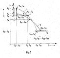
- FIG. 3 shows only part of a standard curve S and one evaluation curve I, namely that between two standard reference points R sa , C sa ; R sb , C sb or two calculation bases R ia , C ia ; R ib , C ib lying part.
- the calculation reference points each lie on straight lines that run parallel to a coordinate of the coordinate system.
- the drawing shows ten calculation bases assigned to the standard bases R sa , C sa and R sb , C sb .
- the calculation bases R1 a , C1 a assigned to the standard base R sa , C sa ; ...; R10 a , C10 a lie on the straight line a, which runs parallel to the ordinate of the coordinate system.
- the R value is the same for all calculation bases and corresponds to the R value of the associated standard base R sb .
- a diffuse reflectivity of the value R ix is measured.
- the true evaluation curve of the test carrier used is shown in dashed lines in FIG. 3 and labeled I.
- the horizontal defined by the measured value R ix intersects the curve I at point P, so the concentration value assigned to this point P is the true concentration value that is to be determined.
- the present invention is now achieved with a very small effort a much better approximation to the true evaluation curve by ix from the measured value R first a Standardmeßwert R sx on the standard curve south and then from the Standardmeßwert R sx corresponding concentration value C sx the sought concentration value C ix is calculated.
- the calculation reference points closest to the measured value R ix e.g. R ia -R ib
- the distance between the two R values of the standard reference points e.g. R sa -R sb
- the invention is essentially based on the knowledge that with a suitable choice of the calculation reference points and the standard reference points as well as a curve course of the standard curve similar to the evaluation curves, the relative change of a remission value compared to the neighboring calculation reference point values is surprisingly similar to the corresponding change on the standard curve compared to the standard bases.
- the ratio ⁇ is first formed from the distance of the measured value R ix from the neighboring calculation base R ia to the distance between the calculation bases R ia and R ib . This ratio is multiplied by the distance between the standard reference points R sa and R sb and the relative reflectance drop compared to the standard reference point R sa is subtracted from this. The result is the standard measured value R sx , which represents the value on the standard curve corresponding to the measured diffuse reflectance R ix in the sense of the present invention.
- This value R sx corresponds to a concentration value C sx on the standard curve S.
- This value is now converted in a corresponding approximation method, taking into account, on the one hand, the distance between the concentration values C ia , C ib of the neighboring calculation bases and, on the other hand, the concentration values of the adjacent standard bases C sa , C sb .
- the relationship between the distance of the value C sx from the adjacent standard concentration value C sa to the distance between the standard concentration values C sa and C sb is formed.
- This ratio ⁇ is multiplied by the distance between the two concentration values of the calculation bases C ib and C ia and added to the concentration value C ia of the adjacent calculation base.
- the concentration value C ix is obtained. This does not correspond exactly, but in a very good approximation to the concentration value to be measured. This is illustrated in FIG. 3 in that the point C ix , R ix deviates slightly from the point P lying on the true evaluation curve.
- a large number of test carrier batches are produced and the associated evaluation curves are measured precisely.
- a first standard curve is laid so that it runs approximately in the middle of the evaluation curves.
- the standard reference points are first placed exactly on the turning points of the standard curve and on the ends of the measuring range.
- the standard bases are used to lay straight or only slightly curved curves at an obtuse angle to the course of the standard curve in the respective standard base. For the sake of simplicity, one should preferably first try straight lines that run parallel to the axes of the coordinate system. This is used to define calculation bases that are equidistant from each other. The distances and the distribution of the calculation bases on both sides of the standard base are chosen so that the outermost calculation bases are still outside the outermost evaluation curves of the test carrier batches examined.
- the invention can advantageously also be used for evaluation devices in which several different types of test carriers can be measured, i. H. with which the determination of several different parameters is possible.
- the standard curve, the standard reference points and the calculation reference points can be saved separately for each test carrier type.
- the same calculation points or standard points and, under certain circumstances, also parts of the course of the standard curves are used together for several types of test carriers. This saves storage capacity.
- the respective assigned combination of calculation bases must be selected separately for each test carrier batch of a specific test carrier type. If, for example, three sets of calculation bases are available for each test carrier type, the selection can expediently be made by a sequence of four characters. The first character then characterizes the test carrier type. The other three characters characterize the selection of the calculation bases from the finite supply of the calculation bases stored for the respective test carrier type.
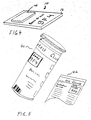
- test carrier 10 shows an example of how the visible characters, on the basis of which the calculation bases are selected, are attached to a test carrier 10.
- it is the alphanumeric characters "9F4", on the basis of which three calculation bases are selected from a set of 16 calculation bases each. They are applied to the base 12 of the test carrier 10. All test carriers in a production batch have the same visible signs.
- FIG. 5 shows an example in which the visible characters are applied to a test carrier packaging 40 and / or a corresponding package insert 42. This method simplifies production because not every test carrier has to be printed with the visible sign.
Landscapes
- Health & Medical Sciences (AREA)
- Engineering & Computer Science (AREA)
- Physics & Mathematics (AREA)
- Life Sciences & Earth Sciences (AREA)
- Biomedical Technology (AREA)
- Chemical & Material Sciences (AREA)
- Analytical Chemistry (AREA)
- Pathology (AREA)
- Immunology (AREA)
- General Physics & Mathematics (AREA)
- General Health & Medical Sciences (AREA)
- Biochemistry (AREA)
- Hematology (AREA)
- Mathematical Physics (AREA)
- Food Science & Technology (AREA)
- Urology & Nephrology (AREA)
- Molecular Biology (AREA)
- Biophysics (AREA)
- Optics & Photonics (AREA)
- Medicinal Chemistry (AREA)
- Theoretical Computer Science (AREA)
- Spectroscopy & Molecular Physics (AREA)
- Investigating Or Analysing Biological Materials (AREA)
- Measurement Of The Respiration, Hearing Ability, Form, And Blood Characteristics Of Living Organisms (AREA)
- Measuring And Recording Apparatus For Diagnosis (AREA)
- Investigating Or Analyzing Non-Biological Materials By The Use Of Chemical Means (AREA)
- Investigating Or Analysing Materials By The Use Of Chemical Reactions (AREA)
- Sampling And Sample Adjustment (AREA)
Priority Applications (1)
| Application Number | Priority Date | Filing Date | Title |
|---|---|---|---|
| AT87106932T ATE50646T1 (de) | 1986-05-22 | 1987-05-13 | System zur bestimmung der konzentration von bestandteilen von koerperfluessigkeiten. |
Applications Claiming Priority (2)
| Application Number | Priority Date | Filing Date | Title |
|---|---|---|---|
| DE3617161 | 1986-05-22 | ||
| DE19863617161 DE3617161A1 (de) | 1986-05-22 | 1986-05-22 | System zur bestimmung der konzentration von bestandteilen von koerperfluessigkeiten |
Publications (3)
| Publication Number | Publication Date |
|---|---|
| EP0247439A2 true EP0247439A2 (fr) | 1987-12-02 |
| EP0247439A3 EP0247439A3 (en) | 1988-07-20 |
| EP0247439B1 EP0247439B1 (fr) | 1990-02-28 |
Family
ID=6301336
Family Applications (1)
| Application Number | Title | Priority Date | Filing Date |
|---|---|---|---|
| EP87106932A Expired - Lifetime EP0247439B1 (fr) | 1986-05-22 | 1987-05-13 | Système de détermination de la concentration de composants de liquides corporels |
Country Status (7)
| Country | Link |
|---|---|
| US (1) | US4852025A (fr) |
| EP (1) | EP0247439B1 (fr) |
| JP (1) | JPS62285040A (fr) |
| AT (1) | ATE50646T1 (fr) |
| DE (2) | DE3617161A1 (fr) |
| HK (1) | HK46393A (fr) |
| SG (1) | SG17093G (fr) |
Cited By (4)
| Publication number | Priority date | Publication date | Assignee | Title |
|---|---|---|---|---|
| EP0383322A3 (fr) * | 1989-02-17 | 1991-04-24 | Fuji Photo Film Co., Ltd. | Appareil d'analyses biochimiques, méthode de correction des résultats de ces analyses et support d'enregistrement des corrections |
| EP0392283A3 (fr) * | 1989-04-08 | 1993-02-24 | Roche Diagnostics GmbH | Système d'analyse de support de test |
| EP0618438A1 (fr) * | 1993-03-29 | 1994-10-05 | Siemens Aktiengesellschaft | Procédé d'étalonnage d'un dispositif de mesure, en particulier d'un photomètre d'absorption infrarouge |
| EP0660114A3 (fr) * | 1993-12-22 | 1996-01-31 | Clinical Diagnostic Syst | Méthode pour récalibrage d'un analyseur. |
Families Citing this family (36)
| Publication number | Priority date | Publication date | Assignee | Title |
|---|---|---|---|---|
| US4933844A (en) * | 1988-09-26 | 1990-06-12 | Otvos James D | Measurement of blood lipoprotein constituents by analysis of data acquired from an NMR spectrometer |
| KR910002093B1 (ko) * | 1989-05-02 | 1991-04-03 | 삼성전자 주식회사 | 혈당값 측정장치 및 그의 제어방법 |
| US5067092A (en) * | 1990-01-24 | 1991-11-19 | Eastman Kodak Company | Prespot detection method and apparatus in an analyzer |
| US4995398A (en) * | 1990-04-30 | 1991-02-26 | Turnidge Patrick A | Coronary angiography imaging system |
| US5099437A (en) * | 1990-10-09 | 1992-03-24 | Fugitive Emissions Control, Inc. | Emissions monitoring and tracking system |
| DE4117847A1 (de) * | 1991-05-31 | 1992-12-03 | Lre Relais & Elektronik Gmbh | Verfahren zum auswerten binaerer informationen |
| WO1993003450A1 (fr) * | 1991-07-30 | 1993-02-18 | North Carolina State University | Procede et appareil pour mesurer les taux sanguins de lipoproteines par spectroscopie rmn |
| US5429129A (en) * | 1991-08-22 | 1995-07-04 | Sensor Devices, Inc. | Apparatus for determining spectral absorption by a specific substance in a fluid |
| US5353790A (en) * | 1992-01-17 | 1994-10-11 | Board Of Regents, The University Of Texas System | Method and apparatus for optical measurement of bilirubin in tissue |
| US5448499A (en) * | 1992-08-24 | 1995-09-05 | Olin Corporation | Mispour-misfill prevention apparatus and process |
| US5479359A (en) * | 1993-03-17 | 1995-12-26 | Metcalf & Eddy, Inc. | Automated data collection system for fugitive emission sources |
| US5695949A (en) * | 1995-04-07 | 1997-12-09 | Lxn Corp. | Combined assay for current glucose level and intermediate or long-term glycemic control |
| US5699794A (en) * | 1995-12-19 | 1997-12-23 | Neopath, Inc. | Apparatus for automated urine sediment sample handling |
| US5989917A (en) * | 1996-02-13 | 1999-11-23 | Selfcare, Inc. | Glucose monitor and test strip containers for use in same |
| US6271920B1 (en) | 1997-12-19 | 2001-08-07 | Chromatics Color Sciences International, Inc. | Methods and apparatus for color calibration and verification |
| DE10105549A1 (de) * | 2001-02-06 | 2002-08-29 | Roche Diagnostics Gmbh | System zur Überwachung der Konzentration von Analyten in Körperflüssigkeiten |
| DE10163775A1 (de) | 2001-12-22 | 2003-07-03 | Roche Diagnostics Gmbh | Analysensystem zur Bestimmung einer Analytkonzentration unter Berücksichtigung von proben- und analytunabhängigen Lichtintensitätsänderungen |
| US8989833B2 (en) | 2004-07-13 | 2015-03-24 | Dexcom, Inc. | Transcutaneous analyte sensor |
| DE102004054551B4 (de) * | 2004-11-11 | 2021-07-22 | Orgentec Diagnostika Gmbh | Vorrichtung zur vollautomatischen Durchführung eines Einzelimmunoassays |
| US9788771B2 (en) | 2006-10-23 | 2017-10-17 | Abbott Diabetes Care Inc. | Variable speed sensor insertion devices and methods of use |
| US8016154B2 (en) * | 2005-05-25 | 2011-09-13 | Lifescan, Inc. | Sensor dispenser device and method of use |
| US20080274552A1 (en) * | 2007-05-04 | 2008-11-06 | Brian Guthrie | Dynamic Information Transfer |
| US8001825B2 (en) * | 2007-11-30 | 2011-08-23 | Lifescan, Inc. | Auto-calibrating metering system and method of use |
| US11730407B2 (en) | 2008-03-28 | 2023-08-22 | Dexcom, Inc. | Polymer membranes for continuous analyte sensors |
| US9402544B2 (en) | 2009-02-03 | 2016-08-02 | Abbott Diabetes Care Inc. | Analyte sensor and apparatus for insertion of the sensor |
| CA2766685A1 (fr) | 2010-03-24 | 2011-12-29 | Abbott Diabetes Care Inc. | Appareils d'insertion de dispositifs medicaux et procedes d'insertion et d'utilisation de dispositifs medicaux |
| WO2013090215A2 (fr) | 2011-12-11 | 2013-06-20 | Abbot Diabetes Care Inc. | Dispositifs détecteurs d'analytes, connexions, et procédés |
| AU2016260547B2 (en) | 2015-05-14 | 2020-09-03 | Abbott Diabetes Care Inc. | Compact medical device inserters and related systems and methods |
| US10213139B2 (en) | 2015-05-14 | 2019-02-26 | Abbott Diabetes Care Inc. | Systems, devices, and methods for assembling an applicator and sensor control device |
| IT201600094056A1 (it) * | 2016-09-20 | 2018-03-20 | Bilimetrix S R L | Metodo di taratura per un dispositivo di misura della bilirubina |
| CN115444410B (zh) | 2017-01-23 | 2025-08-15 | 雅培糖尿病护理公司 | 用于插入体内分析物传感器的施加器及组件 |
| WO2020131159A1 (fr) | 2018-12-21 | 2020-06-25 | Abbott Diabetes Care Inc. | Systèmes, dispositifs et procédés d'insertion de capteur d'analyte |
| CN115942909A (zh) | 2020-08-31 | 2023-04-07 | 雅培糖尿病护理公司 | 用于分析物传感器插入的系统、装置和方法 |
| ES3000715T3 (en) | 2020-09-15 | 2025-03-03 | Abbott Diabetes Care Inc | Device for analyte monitoring |
| MY202051A (en) | 2021-07-16 | 2024-03-30 | Abbott Diabetes Care Inc | Systems, devices, and methods for analyte monitoring |
| CN114780905B (zh) * | 2022-06-21 | 2022-09-13 | 四川大学华西医院 | 一种比对样本的确定方法及装置、存储介质、电子设备 |
Family Cites Families (15)
| Publication number | Priority date | Publication date | Assignee | Title |
|---|---|---|---|---|
| US4125828A (en) * | 1972-08-04 | 1978-11-14 | Med-El Inc. | Method and apparatus for automated classification and analysis of cells |
| GB1538225A (en) * | 1975-02-28 | 1979-01-10 | Nat Res Dev | Methods and apparatus for analysing frequency distributions |
| DE2542674A1 (de) * | 1975-09-25 | 1977-03-31 | Bernd Dr Schmidt | Durch eine dv-anlage gesteuerte probenidentifikation und verteilungsstrategie fuer ein klinisch-chemisches labor |
| US4281387A (en) * | 1979-05-21 | 1981-07-28 | American Home Products Corp. | Automatic chemical analysis apparatus and method |
| JPS56155835A (en) * | 1980-05-02 | 1981-12-02 | Olympus Optical Co Ltd | Component analyzing method |
| US4612614A (en) * | 1980-09-12 | 1986-09-16 | International Remote Imaging Systems, Inc. | Method of analyzing particles in a fluid sample |
| US4420564A (en) * | 1980-11-21 | 1983-12-13 | Fuji Electric Company, Ltd. | Blood sugar analyzer having fixed enzyme membrane sensor |
| DE3133826A1 (de) * | 1981-08-27 | 1983-03-10 | Boehringer Mannheim Gmbh, 6800 Mannheim | Analyseteststreifen und verfahren zu seiner herstellung |
| DE3326689A1 (de) * | 1983-07-23 | 1985-01-31 | Boehringer Mannheim Gmbh, 6800 Mannheim | Verfahren und vorrichtung zur herstellung eines teststreifens |
| JPH0737946B2 (ja) * | 1983-08-05 | 1995-04-26 | 株式会社京都第一科学 | 体液成分を測定するとともにその検査データを保存管理する装置 |
| US4642778A (en) * | 1984-03-02 | 1987-02-10 | Indiana University Foundation | Method and device for spectral reconstruction |
| US4720788A (en) * | 1984-06-20 | 1988-01-19 | Helena Laboratories Corporation | Diagnostic densitometer |
| JPS61151445A (ja) * | 1984-12-25 | 1986-07-10 | Omron Tateisi Electronics Co | 生化学測定装置 |
| US4706207A (en) * | 1985-06-24 | 1987-11-10 | Nova Celltrak, Inc. | Count accuracy control means for a blood analyses system |
| JPS623648A (ja) * | 1985-06-28 | 1987-01-09 | Omron Tateisi Electronics Co | 尿糖測定装置 |
-
1986
- 1986-05-22 DE DE19863617161 patent/DE3617161A1/de not_active Withdrawn
-
1987
- 1987-02-11 US US07/013,396 patent/US4852025A/en not_active Expired - Lifetime
- 1987-05-13 AT AT87106932T patent/ATE50646T1/de not_active IP Right Cessation
- 1987-05-13 EP EP87106932A patent/EP0247439B1/fr not_active Expired - Lifetime
- 1987-05-13 DE DE8787106932T patent/DE3761786D1/de not_active Expired - Lifetime
- 1987-05-22 JP JP62124099A patent/JPS62285040A/ja active Granted
-
1993
- 1993-02-16 SG SG170/93A patent/SG17093G/en unknown
- 1993-05-13 HK HK463/93A patent/HK46393A/xx not_active IP Right Cessation
Cited By (6)
| Publication number | Priority date | Publication date | Assignee | Title |
|---|---|---|---|---|
| EP0383322A3 (fr) * | 1989-02-17 | 1991-04-24 | Fuji Photo Film Co., Ltd. | Appareil d'analyses biochimiques, méthode de correction des résultats de ces analyses et support d'enregistrement des corrections |
| US5122969A (en) * | 1989-02-17 | 1992-06-16 | Fuji Photo Film Co., Ltd. | Biochemical analysis apparatus, method for correcting the results of biochemical analyses, and correction value recording medium for the same |
| EP0392283A3 (fr) * | 1989-04-08 | 1993-02-24 | Roche Diagnostics GmbH | Système d'analyse de support de test |
| EP0618438A1 (fr) * | 1993-03-29 | 1994-10-05 | Siemens Aktiengesellschaft | Procédé d'étalonnage d'un dispositif de mesure, en particulier d'un photomètre d'absorption infrarouge |
| EP0660114A3 (fr) * | 1993-12-22 | 1996-01-31 | Clinical Diagnostic Syst | Méthode pour récalibrage d'un analyseur. |
| US5554539A (en) * | 1993-12-22 | 1996-09-10 | Johnson & Johnson Clinical Diagnostics, Inc. | Determination of an analyte |
Also Published As
| Publication number | Publication date |
|---|---|
| DE3761786D1 (de) | 1990-04-05 |
| US4852025A (en) | 1989-07-25 |
| EP0247439A3 (en) | 1988-07-20 |
| SG17093G (en) | 1993-04-16 |
| JPS62285040A (ja) | 1987-12-10 |
| HK46393A (en) | 1993-05-21 |
| DE3617161A1 (de) | 1987-11-26 |
| JPH0516745B2 (fr) | 1993-03-05 |
| EP0247439B1 (fr) | 1990-02-28 |
| ATE50646T1 (de) | 1990-03-15 |
Similar Documents
| Publication | Publication Date | Title |
|---|---|---|
| EP0247439B1 (fr) | Système de détermination de la concentration de composants de liquides corporels | |
| EP0392283B1 (fr) | Système d'analyse de support de test | |
| DE69225292T2 (de) | Vorrichtung und Anwendung zur Messung einer Komponente des menschlichen Körpers | |
| DE2613617C2 (de) | Verfahren zur Analyse von Proben, z.B. Urin | |
| EP0376110B1 (fr) | Analyseur pour bandes de test | |
| DE2902776C2 (fr) | ||
| DE69427743T2 (de) | Verfahren zum Rekalibrieren eines Analysators | |
| DE3908831C2 (fr) | ||
| DE69032977T2 (de) | Biodetektionsinstrument und auswertungsverfahren | |
| EP0492326B1 (fr) | Analyseur pour bandes de test | |
| DE60224846T2 (de) | Diagnose- und/oder analysesystem am behandlungsort | |
| DE69301310T2 (de) | Verfahren zur bestimmung von harnstoff in milch | |
| EP2316023B1 (fr) | Système d'analyse avec reconnaissance de codage | |
| EP0259797A2 (fr) | Dispositif d'évaluation de bandes d'essai | |
| DE102016202428B4 (de) | Messsystem für colorimetrische Assays | |
| DE2502013B2 (fr) | ||
| EP1238274A2 (fr) | Systeme d'analyse pour element d'essai, dote d'un detecteur infrarouge | |
| DE69024453T2 (de) | Verbessertes Kalibrierungsverfahren | |
| EP0420108B1 (fr) | Pyromètre à plusieurs longueurs d'onde | |
| DE10156809B4 (de) | Verfahren und Vorrichtung zur Blutzuckermessung | |
| DE69432491T2 (de) | Überwachungsverfahren der Fertilität | |
| DE69326575T2 (de) | Testverfahren für Proben unter Verwendung flacher Probenträger | |
| DE69934950T2 (de) | Verfahren und System zur Kalibrierung und Messung in einer Mikrodialyseeinrichtung | |
| DE69424257T2 (de) | Verfahren zum Justieren eines Kolorimeters | |
| EP1189064B1 (fr) | Méthode pour vérifier l'utilisabilité d'éléments d'essai |
Legal Events
| Date | Code | Title | Description |
|---|---|---|---|
| PUAI | Public reference made under article 153(3) epc to a published international application that has entered the european phase |
Free format text: ORIGINAL CODE: 0009012 |
|
| 17P | Request for examination filed |
Effective date: 19870513 |
|
| AK | Designated contracting states |
Kind code of ref document: A2 Designated state(s): AT BE CH DE ES FR GB GR IT LI LU NL SE |
|
| PUAL | Search report despatched |
Free format text: ORIGINAL CODE: 0009013 |
|
| AK | Designated contracting states |
Kind code of ref document: A3 Designated state(s): AT BE CH DE ES FR GB GR IT LI LU NL SE |
|
| 17Q | First examination report despatched |
Effective date: 19881107 |
|
| GRAA | (expected) grant |
Free format text: ORIGINAL CODE: 0009210 |
|
| AK | Designated contracting states |
Kind code of ref document: B1 Designated state(s): AT BE CH DE ES FR GB GR IT LI LU NL SE |
|
| PG25 | Lapsed in a contracting state [announced via postgrant information from national office to epo] |
Ref country code: SE Effective date: 19900228 Ref country code: GR Free format text: LAPSE BECAUSE OF FAILURE TO SUBMIT A TRANSLATION OF THE DESCRIPTION OR TO PAY THE FEE WITHIN THE PRESCRIBED TIME-LIMIT Effective date: 19900228 |
|
| REF | Corresponds to: |
Ref document number: 50646 Country of ref document: AT Date of ref document: 19900315 Kind code of ref document: T |
|
| ITF | It: translation for a ep patent filed | ||
| REF | Corresponds to: |
Ref document number: 3761786 Country of ref document: DE Date of ref document: 19900405 |
|
| ET | Fr: translation filed | ||
| GBT | Gb: translation of ep patent filed (gb section 77(6)(a)/1977) | ||
| PG25 | Lapsed in a contracting state [announced via postgrant information from national office to epo] |
Ref country code: LU Free format text: LAPSE BECAUSE OF NON-PAYMENT OF DUE FEES Effective date: 19900531 |
|
| PG25 | Lapsed in a contracting state [announced via postgrant information from national office to epo] |
Ref country code: ES Free format text: LAPSE BECAUSE OF FAILURE TO SUBMIT A TRANSLATION OF THE DESCRIPTION OR TO PAY THE FEE WITHIN THE PRESCRIBED TIME-LIMIT Effective date: 19900608 |
|
| PLBE | No opposition filed within time limit |
Free format text: ORIGINAL CODE: 0009261 |
|
| STAA | Information on the status of an ep patent application or granted ep patent |
Free format text: STATUS: NO OPPOSITION FILED WITHIN TIME LIMIT |
|
| 26N | No opposition filed | ||
| ITTA | It: last paid annual fee | ||
| PGFP | Annual fee paid to national office [announced via postgrant information from national office to epo] |
Ref country code: DE Payment date: 20010508 Year of fee payment: 15 |
|
| PGFP | Annual fee paid to national office [announced via postgrant information from national office to epo] |
Ref country code: GB Payment date: 20010509 Year of fee payment: 15 |
|
| PGFP | Annual fee paid to national office [announced via postgrant information from national office to epo] |
Ref country code: CH Payment date: 20010511 Year of fee payment: 15 |
|
| PGFP | Annual fee paid to national office [announced via postgrant information from national office to epo] |
Ref country code: AT Payment date: 20010514 Year of fee payment: 15 |
|
| PGFP | Annual fee paid to national office [announced via postgrant information from national office to epo] |
Ref country code: FR Payment date: 20010518 Year of fee payment: 15 |
|
| PGFP | Annual fee paid to national office [announced via postgrant information from national office to epo] |
Ref country code: NL Payment date: 20010531 Year of fee payment: 15 |
|
| PGFP | Annual fee paid to national office [announced via postgrant information from national office to epo] |
Ref country code: BE Payment date: 20010717 Year of fee payment: 15 |
|
| REG | Reference to a national code |
Ref country code: GB Ref legal event code: IF02 |
|
| PG25 | Lapsed in a contracting state [announced via postgrant information from national office to epo] |
Ref country code: GB Free format text: LAPSE BECAUSE OF NON-PAYMENT OF DUE FEES Effective date: 20020513 Ref country code: AT Free format text: LAPSE BECAUSE OF NON-PAYMENT OF DUE FEES Effective date: 20020513 |
|
| PG25 | Lapsed in a contracting state [announced via postgrant information from national office to epo] |
Ref country code: LI Free format text: LAPSE BECAUSE OF NON-PAYMENT OF DUE FEES Effective date: 20020531 Ref country code: CH Free format text: LAPSE BECAUSE OF NON-PAYMENT OF DUE FEES Effective date: 20020531 Ref country code: BE Free format text: LAPSE BECAUSE OF NON-PAYMENT OF DUE FEES Effective date: 20020531 |
|
| PG25 | Lapsed in a contracting state [announced via postgrant information from national office to epo] |
Ref country code: NL Free format text: LAPSE BECAUSE OF NON-PAYMENT OF DUE FEES Effective date: 20021201 |
|
| PG25 | Lapsed in a contracting state [announced via postgrant information from national office to epo] |
Ref country code: DE Free format text: LAPSE BECAUSE OF NON-PAYMENT OF DUE FEES Effective date: 20021203 |
|
| GBPC | Gb: european patent ceased through non-payment of renewal fee |
Effective date: 20020513 |
|
| REG | Reference to a national code |
Ref country code: CH Ref legal event code: PL |
|
| PG25 | Lapsed in a contracting state [announced via postgrant information from national office to epo] |
Ref country code: FR Free format text: LAPSE BECAUSE OF NON-PAYMENT OF DUE FEES Effective date: 20030131 |
|
| NLV4 | Nl: lapsed or anulled due to non-payment of the annual fee |
Effective date: 20021201 |
|
| REG | Reference to a national code |
Ref country code: FR Ref legal event code: ST |
|
| PG25 | Lapsed in a contracting state [announced via postgrant information from national office to epo] |
Ref country code: IT Free format text: LAPSE BECAUSE OF NON-PAYMENT OF DUE FEES Effective date: 20050513 |